

Page 1
SIL Certified Safety Manual for
Enhanced Model 705-51AX-XXX
Functional Safety Manual
Software v3.x
Guided Wave Radar
Level Transmitter
This manual complements and is intended to be used with the
®
Eclipse
(Bulletin 57-600 dated August 2005 or later).
Safety Function
Enhanced Model 705 Installation and Operating manual
The HART
Guided Wave Radar (GWR) transmitter will measure
level and transmit a signal proportional to that level
within the stated safety accuracy of ±2% of span or the
measured error published in I/O Manual 57- 600,
whichever is greater. In addition, when continuous,
automatic diagnostics detect that the transmitter cannot
perform this function, the output will be driven to the
customer-specified out-of-range signal (i.e., less than
3.8 mA or greater than 20.5 mA).
The Enhanced Model 705 is certified for use in low
demand level measurement applications.
Application
The Enhanced Model 705 Guided Wave Radar level
transmitter can be applied in most process or storage
vessels, bridles, and bypass chambers up to the probe’s
rated temperature and pressure. The Enhanced Model 705
can be used in liquids, slurries or solids to meet the safety
system requirements of IEC 61508/IEC 61511-1.
®
version of the Eclipse®Enhanced Model 705
Benefits
• Level protection to SIL 3 as certified by exida
Certification per IEC 61508/IEC 61511-1.
• Probe designs to +800° F (+427° C),
6250 psig (430 bar) and full vacuum
• Cryogenic applications to -320° F (-190° C)
• IS, XP and Non-Incendive approvals
• Ability to measure reliably to the very top of the vessel.
(Meets TÜV: WHG 19 overfill specifications when
used with Model 7xD, 7xG, 7xR, and 7xT probes).
Page 2
Eclipse®Enhanced Model 705 Guided Wave Radar Level Transmitter
SIL Certified Safety Manual for Enhanced Model 705-51AX-XXX
Table of Contents
1.0 Introduction ...................................................................3
1.1 Theory of Operation.................................................3
1.2 Product Description..................................................3
1.3 Determining Safety Integrity Level (SIL) ..................3
2.0 Level Measuring System .................................................4
2.0.1 Digital Communication Protocols..................4
2.1 Applicable Models.....................................................4
2.2 Miscellaneous Electrical Considerations ....................5
2.2.1 Pollution Degree 2 .........................................5
2.2.2 Overvoltage....................................................5
3.0 Mean Time To Repair (MTTR).....................................5
4.0 Supplemental Documentation........................................5
5.0 Instructions ....................................................................6
5.1 Systematic Limitations ..............................................6
5.1.1 Application.....................................................6
5.1.2 Environmental................................................6
5.2 Skill Level of Personnel .............................................6
5.3 Necessary Tools.........................................................6
5.4 Storage ......................................................................7
5.5 Installation ................................................................7
5.6 Configuration ...........................................................7
5.6.1 General...........................................................7
5.6.2 SIS Configuration Requirements....................8
5.6.3 Write Protecting/Locking ..............................8
5.7 Site Acceptance Testing .............................................9
5.8 Maintenance ..............................................................9
5.8.1 Diagnostics and Response Times....................9
5.8.2 Troubleshooting ...........................................10
6.0 Recurrent Function Tests .............................................10
6.1 Proof Testing ...........................................................10
6.1.1 Introduction.................................................10
6.1.2 Interval.........................................................10
6.1.3 Recording Results.........................................10
6.1.4 Proof Test Procedure.....................................11
7.0 Report: Lifetime of Critical Components .....................12
8.0 Appendices ...................................................................12
8.1 Specific Model 705-5 values....................................12
8.2 PFD Chart..............................................................12
8.3 SSA, Safety System Assumptions.............................13
8.4 FMEDA Report : exida Management Summary ......14
57-651 Eclipse®SIL Certified Safety Manual for Enhanced Model 705-51AX-XXX
Page 3
Table 1
Enhanced ECLIPSE Model Numbers
1 Transmitters:
Model 705, 705-51A*-*** (HART)
NOTE: All transmitters shipped
after August 18, 2010 (serial numbers
667050-01-001 and later) are certified.
2 Probes:
All ECLIPSE probes can be utilized.
Refer to I/O Manual 57-600 for
complete probe offering.
1.0 Introduction
1.1 Theory of Operation
Guided Wave Radar is based upon the principle of TDR
(Time Domain Reflectometry). TDR utilizes high frequency
pulses of electromagnetic energy transmitted down a probe.
When a pulse reaches a surface that has a higher dielectric
than the air/vapor in which it is traveling, the pulse is
reflected. An ultra high-speed timing circuit precisely measures
the transit time and provides an accurate level measurement.
1.2 Product Description
The Enhanced ECLIPSE Model 705 is a loop-powered,
24 VDC level transmitter using GWR technology.
For Safety Instrumented Systems usage, the 4–20 mA analog output is the safety variable. The analog output meets
the requirements of NAMUR NE 43 (3.8 mA to 20.5 mA
usable). The transmitter contains continuous self-diagnostics, and upon internal detection of a failure, is programmed
to send its output to a user-selected failure state, either low
or high. This failsafe state is defined as the Faulted Mode.
Table 1 shows the version of the ECLIPSE Enhanced
Model 705 transmitter that has been certified for SIL 2/3
protection.
Table 2
SIL vs. PFD
Integrity Level
AVG
Safety
(SIL)
4 ≥10-5to <10
3 ≥10-4to <10
2 ≥10-3to <10
1 ≥10-2to <10
Target Average
probability of failure
on demand (PFD
)
AVG
-4
-3
-2
-1
Table 3
Minimum hardware fault tolerance
Type B sensors, final elements and non-PE logic solvers
Hardware Fault
SFF
None: <60%
Low: 60% to <90% SIL 1 SIL 2 SIL 3
Medium: 90% to <99% SIL 2 SIL 3
High: ≥99% SIL 3
Tolerance (HFT)
0 1 2
Not
Allowed
SIL 1 SIL 2
The Enhanced ECLIPSE Model 705 is classified as a Type B
Device as defined by IEC61508.
1.3 Determining Safety Integrity Level (SIL)
Safety Instrumented System designers using the Enhanced
ECLIPSE Model 705 must verify their design per applicable
standards, including IEC 61511-1.
Three limits must be met to achieve a given SIL level:
1. The PFD
numbers for the entire Safety Instrumented
AVG
Function (SIF) must be calculated. Table 2 shows the relationship between the Safety Integrity Level (SIL) and the
Probability of Failure on Demand Average (PFD
AVG
2. Architecture constraints must be met for each subsystem.
Table 3 can be used to determine the achievable SIL as a
function of the Hardware Fault Tolerance (HFT) and the
Safe Failure Fraction (SFF) for each subsystem in a safety
system (Type B–complex components as per IEC 61508
Part 2) of which the level transmitter is just one component.
).
57-651 Eclipse®SIL Certified Safety Manual for Enhanced Model 705-51AX-XXX
3
Page 4
3. All products chosen for use in the SIF must meet the
Actuator
PACTware™with
Eclipse®3.x DTM
HART Modem
Eclipse
®
Model 705
Logic
Unit
requirements of IEC 61508 for the given SIL Capability
level or be justified based on proven in use data collected for
each job.
The exSILentia tool from exida is recommended for design
verification. This automatically checks all three limits and
displays the results for any given design. The Enhanced
ECLIPSE Model 705 is in the exSILentia database. This
tool contains all needed failure rate, failure mode, SIL
Capability and common cause data as well as suggested
proof test methods.
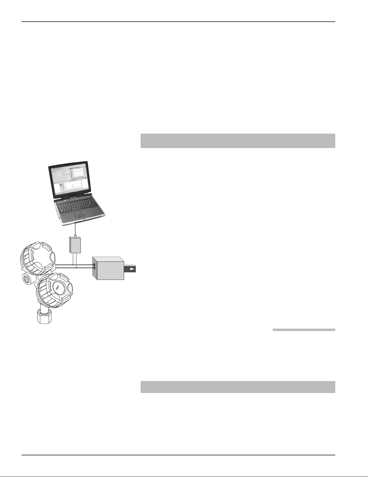
2.0 Level Measuring System
Figure 1 shows the structure of a typical measurement
system incorporating the Enhanced Magnetrol
Model 705 Guided Wave Radar transmitter.
This SIL 2/3 certified device is only available with an analog
signal (4–20 mA) with HART digital communications.
The measurement signal used by the logic unit must be the
generated analog 4–20 mA signal proportional to level.
®
Figure 1
Typical System
For fault monitoring, the logic unit must recognize both a
high alarm (≥ 21.5 mA) and low alarm (≤ 3.6 mA).
NOTE: Care must be taken to ensure the loop continues to operate
properly under a high alarm condition if the logic unit or loop
contains intrinsic safety barriers.
The only unsafe mode is when the unit is reading an
incorrect level within the 4–20mA range: ±2% of span or
the measured error published in I/O Manual 57-600,
whichever is greater. MAGNETROL defines a safe failure
as one in which the 4–20 mA current is driven out of range
(i.e., less than 3.8 mA or greater than 20.5 mA).
2.0.1 Digital Communication Protocols
Although the Enhanced ECLIPSE Model 705 transmitter is
available with F
OUNDATION Fieldbus
™
and PROFIBUS digital communication outputs, HART is the only protocol
included in the present IEC 61508/61511 standard.
2.1 Applicable Models
4
This manual is only applicable to the following Enhanced
ECLIPSE Model 705 Guided Wave Transmitter:
705-51Ax-xxx (SIL 2, HFT 0)
57-651 Eclipse®SIL Certified Safety Manual for Enhanced Model 705-51AX-XXX
Page 5

2.2 Miscellaneous Electrical Considerations
The following are miscellaneous electrical issues that must
be considered in any installation:
2.2.1 Pollution Degree 2
The Enhanced ECLIPSE Model 705 is designed for use in
Category II, Pollution Degree 2 installations.
The usual pollution degree used for equipment being evaluated to IEC/EN 61010 is a nonconductive pollution of the
sort where occasionally a temporary conductivity caused by
condensation is expected.
2.2.2 Overvoltage
The Enhanced ECLIPSE Model 705 has over-voltage protection per the necessary CE requirements. As this protection is
up to 1KV when considering Hi-pot, FastTransients and
Surge, no unsafe failure modes should exist up to this potential.
Overvoltage Category II is a local standard, covering appliances, portable equipment, etc., with smaller transient voltages than those characteristic of Overvoltage Category III.
(This category applies from the wall plug to the power-supply isolation barrier or transformer).
The typical industrial plant environment is Overvoltage
Category II, therefore, most equipment evaluated to the
requirements of IEC/EN 61010 is considered to belong in
this classification.
3.0 Mean Time To Repair (MTTR)
SIL determinations are based on a number of factors,
including the Mean Time To Repair (MTTR). The analysis
for the Enhanced ECLIPSE Model 705 is based on a
MTTR of 24 hours.
4.0 Supplemental Documentation
The Enhanced ECLIPSE Model 705 Installation and
Operating Manual (57-600) must be available and used for
installation of the level transmitter.
If the HART digital protocol will be used, the following
Electronic Device Description Files are also required:
Manufacturer Code 0x56
Model 705 3.x Device ID 0xE5, device revision 1,
DD revision 1.
For device installations in a classified area, the relevant safety
instructions and electrical codes must be followed.
57-651 Eclipse®SIL Certified Safety Manual for Enhanced Model 705-51AX-XXX
5
Page 6

5.0 Instructions
5.1 Systematic Limitations
The following must be observed to avoid systematic failures:
5.1.1 Application
As the probe configuration establishes the fundamental performance characteristics of the system, choosing the proper
Guided Wave Radar probe is the most important decision
in the specification/application process. Coaxial, twin element (rod or cable), and single element (rod or cable) are
the three basic GWR probe configurations. The probe for
use with the SIL 2/3 certified Enhanced ECLIPSE Model 705
must be selected as appropriate for the application (e.g.,
careful selection of probe design and materials for a specific
application will minimize media buildup on the probe).
Refer to Section 3.3.3 of Installation and Operating Manual
57-600 for more detailed application information regarding
media buildup and bridging.
5.1.2 Environmental
Refer to Section 3.6 of Installation and Operating Manual
57-600 for the Model 705 Environmental Specifications.
5.2 Skill Level of Personnel
Personnel following the procedures in this safety manual
should have technical expertise equal to or greater than that
of a qualified Instrument Technician.
5.3 Necessary Tools
Following are the necessary tools required to carry out the
prescribed procedures:
• Open-wrenches or adjustable wrench to fit the process connection size and type.
Coaxial probe 11⁄2" (38mm)
••
Twin Rod probe 17⁄8" (47mm)
••
Transmitter 11⁄2" (38mm)
••
Torque wrench is highly desirable
••
• Flat-blade screwdriver
• Cable cutter and 3⁄32" (2.5mm) hex wrench (7X1, 7X2, 7X5
and 7X7 Flexible probes only)
• Digital multimeters or digital volt/ammeter
• 24 VDC power supply, 23 mA minimum
6
57-651 Eclipse®SIL Certified Safety Manual for Enhanced Model 705-51AX-XXX
Page 7

5.4 Storage
The device should be stored in its original shipping box and
not be subjected to temperatures outside the storage temperature (-50° to +80° C) shown in the ECLIPSE Enhanced
Model 705 Installation and Operating Manual, 57-600.
5.5 Installation
Refer to the Enhanced ECLIPSE Model 705 Installation
and Operating Manual 57-600 manual for the proper
installation instructions.
Section 2.6.4 of I/O Manual 57-600 contains information
regarding the use, changing, and resetting of the password
protection function.
Section 2.6.5.1 of I/O Manual 57-600 provides menu selection items for configuration of the transmitter as a Level
Only sensing device.
See Section 5.6 of this manual for configuration recommendations with respect to using the Enhanced ECLIPSE
Model 705 in a SIS.
As stated in Section 2.0, this SIL evaluation has assumed
that the customer will be able to acknowledge an “over or
under” output current condition via the Logic Unit.
Refer to section 8.3 for Safety System Assumptions (SSA).
5.6 Configuration
5.6.1 General
The MAGNETROL Model 705 can be configured via the
local LCD/keypad, a HART compatible handheld terminal
or with a personal computer containing the proper HART
™
DTM and framework program such as PACTware
NOTE: Parameter changes should not be made through the local display
and the HART interface simultaneously. This is not a safety
consideration because the user of the safety device must
confirm parameter changes per SSA 7. (Refer to page 13.)
5.6.2 SIS Configuration Requirements
.
Ensure the GWR transmitter parameters have been properly
configured for the specific application and probe.
Special consideration should be given to the following configuration parameters:
FAULT: DO NOT choose HOLD for this parameter as a
Fault will not be annunciated on the current loop.
PASSWORD: The Password (default = 0) should be
changed to a specific value other than 0 to ensure the necessary SIS Write/Lock protection.
57-651 Eclipse®SIL Certified Safety Manual for Enhanced Model 705-51AX-XXX
7
Page 8

The following list represents the parameter configuration
required for a Model 705 GWR transmitter intended to
measure overall product level in a SIL 2/3 application.
Please ensure that all Probe-specific parameters are correct
for the GWR probe being used.
PROBE MODEL = As indicated on probe nameplate
PROBE MOUNT = As indicated on probe nameplate
MEASUREMENT TYPE = Level Only
LEVEL UNITS = As indicated on probe nameplate
PROBE LENGTH = As indicated on probe nameplate
LEVEL OFFSET = As required by application
DIELECTRIC = As required by application. (Suggest 1.7–3
for typical hydrocarbon application)
LOOP CONTROL = Level
LOOP CONTROL MODE = Enabled
SET 4mA/SET 20mA = As required by application
DAMPING = As required by application (Default value is 1)
FAULT = As required by application (Default value is
22 mA—do not set to Hold).
BLOCKING DISTANCE = 0 inches
THRESHOLD = Fixed
5.6.3 Write Protection / Locking
Only authorized personnel should be able to change the
transmitter configuration in a device installed in a SIS system.
This requires setting a user password.
The ECLIPSE Model 705 is password protected with a
numerical password between 0 and 255. (Default = 0 means
password is disabled).
The default password must be changed so that password
protection is enabled in a SIS system.
Refer to section 2.6.4 of the Enhanced ECLIPSE Model 705
Installation and Operating Manual 57-600 for additional
information regarding password protection.
Ensure that an exclamation mark (!) appears as the last character on the first line of the LCD to confirm the present
password has been accepted.
When alterations to the configuration are complete, ensure
the menu has been write-locked with the password to prevent inadvertent changes to the device.
8
57-651 Eclipse®SIL Certified Safety Manual for Enhanced Model 705-51AX-XXX
Page 9

For this reason, the Model 705 transmitter has a timeout
feature in which, after 5 minutes with no key presses, the
transmitter will revert back to the scrolling default screen
and a password must be used to make any additional
parameter changes.
NOTE: HART interface shall be interference free assuming the end
user only allows access to HART communication to trained
personnel who may not make any changes to the device
parameters while the device is operational in the SIF.
5.7 Site Acceptance Testing
After installation and configuration is complete, a site
acceptance test should be performed to ensure proper operation. This procedure is identical to the Proof Test Procedure
described in Section 6.1.4 of this manual.
Record the results for future reference. It is also recommended to document the existing transmitter configuration.
Configuration Data Sheets, included at the end of the
I&O Manual 57-600, can be used for this purpose.
5.8 Maintenance
5.8.1 Diagnostics and Response Times
Continuous internal diagnostics are present within the
Enhanced ECLIPSE Model 705 transmitter. In the event a
Fault is detected, a message will appear on the LCD and the
output current will be driven to 3.6 mA or 22mA depending
on how the FAULT parameter is configured.
A) Start-up Time:
a. From application of power to normal operat-
ing mode: 4 seconds
b. From application of power to Fault mode:
29 seconds or less (Assuming a Fault is present
upon start-up)
B) Safety Response Time: 16 seconds
a. This is defined as the time from the normal
operating mode to the Fault mode upon the
occurrence of a fault.
57-651 Eclipse®SIL Certified Safety Manual for Enhanced Model 705-51AX-XXX
9
Page 10

5.8.2 Troubleshooting
Refer to Section 3.3 of the Enhanced ECLIPSE Model 705
I&O Manual 57-600 for troubleshooting the various
device status messages, which can be in the form of
Warnings and Faults.
To assist in finding Faults should they occur, complete the
Configuration Data Sheets included at the end of the
Installation and Operating Manual 57-650. Be sure to
include all device information, both in the working and
non-working modes.
• As there are no moving parts in this device, the only maintenance required is the proof test shown in Section 5.1.
• Firmware can only be upgraded by factory-trained personnel.
• Report all Faults to MAGNETROL technical support.
6.0 Recurrent Function Tests
6.1 Proof Testing
6.1.1 Introduction
Following are the procedures utilized to detect Dangerous
Undetected (DU) failures.
6.1.2 Interval
To maintain the Safety Integrity Level of a Safety
Instrumented System, it is imperative that specified manual
proof testing be completed at the time intervals specified.
The user must select the type of inspection and the time
period for these tests.
The system check must be administered to prove that the protection functions meet the IEC specification, and as important,
result in the desired response of the safety system as a whole.
This system check can be guaranteed when the desired alarm
level height is obtained during the process operation.
If this is not practical, a suitable method of simulating the
level of the physical measurement must be used to allow the
level sensor to respond as if the fluid was filled above the
alarm/set point level.
If the operability of the sensor/transmitter can be determined by other means (that exclude all fault conditions that
may impair the normal functions of the device), the check
may also be completed by simulating the corresponding
output signal of the device.
10
6.1.3 Recording Results
“As Found” and “As Left” results of the Proof Test should be
recorded for future reference.
57-651 Eclipse®SIL Certified Safety Manual for Enhanced Model 705-51AX-XXX
Page 11

6.1.4 Proof Test Procedure
A suggested proof test is described below. This test will
detect approximately 94% of possible DU failures in Model
705-51A*-*** version of the Enhanced ECLIPSE Model 705.
Ensure that all necessary installation and site acceptance test
procedures required to achieve safety are followed.
1. Bypass the safety PLC or take other appropriate action to
avoid a false trip.
2. Send a HART command to force a high alarm current output to the transmitter under test, and verify that the analog
current reaches that value.
This tests for power supply problems such as low supply
voltage or increased loop wiring resistance. It also tests for
other possible failures in the current loop circuitry.
3. Send a HART command to force a low alarm current output to the transmitter under test, and verify that the analog
current reaches that value.
This step tests for possible quiescent current related failures.
4. Remove level from the probe. The Status parameter should
say “Dry Probe” and the level reading should be equal to
the value in the “Level Offset” parameter.
5. Perform a two-point calibration check of the transmitter by
applying level to two different points on the probe and
compare the transmitter display readings and the current
level values to known reference measurements.
6. If the calibration check performed in step 5 is correct, the
proof test is complete. Proceed to step 11.
7. If calibration is incorrect, remove the transmitter and probe
from the process. Inspect the probe for buildup or clogging.
Clean the probe if necessary.
Perform a bench calibration check by shorting the probe
(simulating level) at two different points. Measure the levels
from the bottom of the probe to the simulated levels and
compare to the transmitter display and current level readings.
8. If the calibration is off by more than 2%, contact
MAGNETROL Technical Support for assistance.
9. If the calibration is within tolerance, the proof test is complete. Proceed to step 10.
10. Re-install the probe and transmitter.
11. Restore the loop to full operation.
12. Remove the bypass from the safety PLC or otherwise restore
normal operation.
57-651 Eclipse®SIL Certified Safety Manual for Enhanced Model 705-51AX-XXX
11
Page 12

7.0 Report: Lifetime of Critical Components
Although a constant failure rate is assumed by the probabilistic estimation method, this only applies if the useful
lifetime of components is not exceeded.
Beyond the useful lifetime of a component, the result of
the probabilistic calculation method is meaningless, as the
probability of failure significantly increases with time.
The useful lifetime is highly dependent on the component
itself and its operating conditions—temperature in particular.
(e.g., electrolyte capacitors can be very sensitive).
Within the Enhanced ECLIPSE Model 705, tantalum electrolytic capacitors are the limiting factors with regard to the
useful lifetime of the system. The tantalum electrolytic
capacitors that are used in the transmitter have an estimated
useful lifetime of about 50 years.
8.0 Appendices
8.1 Model 705 SIL Values
Enhanced ECLIPSE Model 705 GWR Transmitter
SIL Values
SIL SIL 2
HFT 0
SFF (High Trip)
SFF (Low Trip)
PFD
Proof Test Interval Annually
8.2 PFD Chart
The resulting PFD
vals are displayed in Figure 2. As shown in the figure the
PFD
value for a single ECLIPSE Enhanced Model 705
AVG
with a proof test interval of 1 year equals 1.06E-03.
AVG
ECLIPSE
Model 705-51Ax-xxx
91.9%
90.4%
9.72E-04
(refer to chart below
for other periods)
values for a variety of proof test inter-
AVG
12
PFD
Figure 2
Values
AVG
57-651 Eclipse®SIL Certified Safety Manual for Enhanced Model 705-51AX-XXX
Page 13

8.3 SSA, System Safety Assumptions
The System Safety Assumptions provide a list of safety relevant assumptions made on the usage of the product over the
safety life cycle of a user Safety Integrity Function, SIF.
MAGNETROL cannot directly control the user life cycle of
a SIF using this product but needs to have assumptions on
how the product will be used. It is important that users
have full knowledge of these assumptions to ensure they are
met when using the product as part of a SIF. This is to
ensure the product is used in a manner consistent with the
safety design.
This section only lists product specific assumptions and is
not intended to specify measures required of the end user
that are standard requirements for safety applications.
Identifier Assumptions for safety Allocated
SSA 1
SSA 2
SSA 3
SSA 4
SSA 5
SSA 6
SSA 7
SSA 8
The user SIF will detect and properly handle annunciation of detected fault conditions
signaled by the alarm level output according to the specific requirements of the SIF.
Proper operation of the ECLIPSE Enhanced Model 705 3x is dependent on having
11 VDC or greater across the transmitter terminals and at least 22 mA available in
the loop during normal operation.
A user SIF integrating the ECLIPSE Enhanced Model 705 3x current loop output will
detect faulted field wiring and other faults resulting in a current loop value signal
outside of the specified range and take proper actions to maintain safety integrity
according to the specific requirements of the SIF.
Optional Local User Interface will not be relied upon by the end user SIF during
normal operation and will be considered non-interfering to the safety function.
HART communications will not be relied upon by the end user for the SIF normal
operation and will be considered non-interfering to the safety function.
The impact of end user configured damping values is not included in the published safety response time. (The end user must consider this as part of overall
time response of the SIF)
The end user will independently verify all changes to end user configured
parameters and validate the safety functionality prior to reliance on the product
for safety protection.
The end user will enable the User Password to lock out any end user modifiable configuration parameters available via the Local User Interface during normal operation.
End user’s responsibility
End user’s responsibility
End user’s responsibility
End user’s responsibility
End user’s responsibility
End user’s responsibility
End user’s responsibility
End user’s responsibility
The end user will allow HART access only to qualified and trained personnel
SSA 9
SSA 10
SSA 11
SSA 12 The end user must not select HOLD for the level alarm output. End user’s responsibility
SSA 13 The HART poll address must be 0. End user’s responsibility
57-651 Eclipse®SIL Certified Safety Manual for Enhanced Model 705-51AX-XXX
because access to all User Password protected parameters is allowed via HART
communication without requiring the entry of the User Password.
The end user will have proper procedures in place to ensure safe operation over
the product lifecycle.
The end user will ensure the device is properly installed per the product literature.
The proper probe will be used for the application with the transmitter properly
connected to the probe.
End user’s responsibility
End user’s responsibility
End user’s responsibility
13
Page 14

8.4 FMEDA Report: exida Management Summary
14
57-651 Eclipse®SIL Certified Safety Manual for Enhanced Model 705-51AX-XXX
Page 15

57-651 Eclipse®SIL Certified Safety Manual for Enhanced Model 705-51AX-XXX
15
Page 16

5300 B elmont Road • Dow ners G rove, Illino is 60515-44 99 • 6 30-96 9-4000 • Fax 630- 969-94 89 • www.magne trol.c om
145 Ja rdin Dr ive, Units 1 & 2 • Con cord, O ntari o Cana da L4K 1X7 • 905- 738-9600 • Fax 90 5-738 -1306
Heiken sstraa t 6 • B 924 0 Zele , Bel gium • 052 45.11. 11 • F ax 05 2 45.0 9.93
Regent Busin ess Ctr., Jubile e Rd. • Bur gess Hill, Sussex RH15 9TL U .K. • 01444 -87131 3 • Fax 014 44-871 317
Copyright © 2012 Magnetrol International, Incorporated. All rights reserved. Printed in the USA.
References
• ANSI/ISA-84.00.01-2004 Part 1 (IEC 61511-1Mod)
“Functional Safety: Safety Instrumented Systems for
he Process Industry Sector—Part 1 Hardware and
t
Software Requirements”
• ANSI/ISA-84.00.01-2004 Part 2 (IEC 61511-2Mod)
• ANSI/ISA-84.00.01-2004 Part 3 (IEC 61511-3Mod)
“Functional Safety: Safety Instrumented Systems for
he Process Industry Sector—Part 3 Guidance for the
t
Determination of the Required Safety Integrity
Levels—Informative”
“Functional Safety: Safety Instrumented Systems for
the Process Industry Sector—Part 2 Guidelines for the
Application of ANSI/ISA84.00.01-2004 Part 1 (IEC
1511-1 Mod)— Informative
Disclaimer
MAGNETROL accepts no liability whatsoever for the use of these numbers or for the correctness of the standards on
which the general calculation methods are based.
ASSURED QUALITY & SERVICE COST LESS
Service Policy
Owners of MAGNETROL controls may request the return
of a control or any part of a control for complete rebuilding
or replacement. They will be rebuilt or replaced promptly.
Controls returned under our service policy must be
returned by prepaid transportation. MAGNETROL will
repair or replace the control at no cost to the purchaser (or
owner) other than transportation if:
1. Returned within the warranty period; and
2. The factory inspection finds the cause of the claim to
be covered under the warranty.
If the trouble is the result of conditions beyond our control; or, is NOT covered by the warranty, there will be
charges for labor and the parts required to rebuild or
replace the equipment.
In some cases it may be expedient to ship replacement
parts; or, in extreme cases a complete new control, to
replace the original equipment before it is returned. If this
is desired, notify the factory of both the model and serial
numbers of the control to be replaced. In such cases, credit for the materials returned will be determined on the
basis of the applicability of our warranty.
No claims for misapplication, labor, direct or consequential damage will be allowed.
Return Material Procedure
So that we may efficiently process any materials that are
returned, it is essential that a “Return Material
Authorization” (RMA) number be obtained from the
factory prior to the material’s return. This is available
through a MAGNETROL local representative or by contacting the factory. Please supply the following information:
1. Company Name
2. Description of Material
3. Serial Number
4. Reason for Return
5. Application
Any unit that was used in a process must be properly
cleaned in accordance with OSHA standards, before it is
returned to the factory.
A Material Safety Data Sheet (MSDS) must accompany
material that was used in any media.
All shipments returned to the factory must be by prepaid
transportation.
All replacements will be shipped F.O.B. factory.
ECLIPSE Guided Wave Radar transmitters may be protected by one or more of the following U.S. Patent Nos.
US 6,626,038; US 6,640,629; US 6,642,807; US 6867729; US 6879282; US 6906662. May depend on model.
Magnetrol, Magnetrol logotype and Eclipse are registered trademarks of Magnetrol International, Incorporated.
OUNDATION fieldbus logo is a registered trademark of the Fieldbus Foundation.
F
HART is a registered trademark of the HART Communication Foundation.
PACTware is trademark of PACTware Consortium.
PROFIBUS is a registered trademark of PROFIBUS International.
BULLETIN: 57-651.2
EFFECTIVE: March 2012
SUPERSEDES: August 2011
 Loading...