

Page 1
Installation and Operating Manual
Enhanced Model 705
Software v3.x
Guided Wave Radar
Level Transmitter
Page 2

Read this Manual Before Installing
®
This manual provides information on the Eclipse
trans-
mitter. It is important that all instructions are read carefully and followed in sequence. The QuickStart
Installation instructions are a brief guide to the sequence
of steps for experienced technicians to follow when
installing the equipment. Detailed instructions are
included in the Complete Installation section of this manual.
Conventions Used in this Manual
Certain conventions are used in this manual to convey
specific types of information. General technical material,
support data, and safety information are presented in
narrative form. The following styles are used for notes,
cautions, and warnings.
NOTES
Notes contain information that augments or clarifies an
operating step. Notes do not normally contain actions.
They follow the procedural steps to which they refer.
Cautions
Cautions alert the technician to special conditions that
could injure personnel, damage equipment, or reduce
a component’s mechanical integrity. Cautions are also
used to alert the technician to unsafe practices or the
need for special protective equipment or specific
materials. In this manual, a caution box indicates a
potentially hazardous situation which, if not avoided,
may result in minor or moderate injury.
WARNINGS
Warnings identify potentially dangerous situations or
serious hazards. In this manual, a warning indicates an
imminently hazardous situation which, if not avoided,
could result in serious injury or death.
Safety Messages
®
The Eclipse
system is designed for use in Category II,
Pollution Degree 2 installations. Follow all standard
industry procedures for servicing electrical and computer
equipment when working with or around high voltage.
Always shut off the power supply before touching any
components. Although high voltage is not present in this
system, it may be present in other systems.
WARNING! Explosion hazard. Do not connect or dis-
connect designs rated Explosion proof or Non-incendive
unless power has been switched off and/or the area is
known to be non-hazardous.
Low Voltage Directive
For use in Installations Category II, Pollution Degree 2.
If equipment is used in a manner not specified by the
manufacturer, protection provided by equipment may be
impaired.
Notice of Copyright and Limitations
®
Magnetrol
registered trademarks of Magnetrol
& Magnetrol®logotype and Eclipse®are
®
International,
Incorporated.
®
Copyright © 2012 Magnetrol
International, Incorporated.
All rights reserved.
MAGNETROL reserves the right to make changes to the
product described in this manual at any time without
notice. MAGNETROL makes no warranty with respect
to the accuracy of the information in this manual.
Warranty
All MAGNETROL electronic level and flow controls are
warranted free of defects in materials or workmanship for
one full year from the date of original factory shipment.
If returned within the warranty period; and, upon factory
inspection of the control, the cause of the claim is
determined to be covered under the warranty; then,
MAGNETROL will repair or replace the control at no
cost to the purchaser (or owner) other than transportation.
MAGNETROL shall not be liable for misapplication,
labor claims, direct or consequential damage or expense
arising from the installation or use of equipment. There
are no other warranties expressed or implied, except special
written warranties covering some MAGNETROL products.
Quality Assurance
The quality assurance system in place at MAGNETROL
guarantees the highest level of quality throughout the
company. MAGNETROL is committed to providing
full customer satisfaction both in quality products and
quality service.
Electrical components are sensitive to electrostatic discharge.
To prevent equipment damage, observe safety procedures
when working with electrostatic sensitive components.
This device complies with Part 15 of the FCC rules.
Operation is subject to the following two conditions:
(1) This device may not cause harmful interference, and
(2) This device must accept any interference received,
including interference that may cause undesired operation.
The MAGNETROL quality assurance
system is registered to ISO 9001 affirming
its commitment to known international
quality standards providing the strongest
assurance of product/service quality
available.
57-600 Eclipse®Guided Wave Radar Transmitter
Page 3

Eclipse®Guided Wave Radar Transmitter
Table of Contents
1.0 QuickStart Installation
1.1 Getting Started..........................................................4
1.1.1 Equipment and Tools .....................................4
1.1.2 Configuration Information.............................5
1.2 QuickStart Mounting................................................5
1.2.1 Probe..............................................................5
1.2.2 Transmitter.....................................................6
1.3 QuickStart Wiring ....................................................6
1.4 QuickStart Configuration .........................................7
2.0 Complete Installation
2.1 Unpacking ................................................................8
2.2 Electrostatic Discharge (ESD) Handling Procedure...8
2.3 Before You Begin.......................................................9
2.3.1 Site Preparation ..............................................9
2.3.2 Equipment and Tools .....................................9
2.3.3 Operational Considerations............................9
2.4 Mounting..................................................................9
2.4.1 Installing a Coaxial Probe.............................10
2.4.1.1 To install a coaxial probe.......................10
2.4.2 Installing a Twin Rod Probe .........................11
2.4.2.1 To install a rigid twin rod probe............11
2.4.2.2 To install a Model 7x7 standard
flexible twin rod probe ..........................12
2.4.3 Installing a Single Rod Probe .......................12
2.4.3.1 Installing a rigid probe ..........................13
2.4.3.2 Installing a flexible probe ......................13
2.4.4 Installation Guidelines–
Models 7x2/7x5 Bulk Solids Probes .............14
2.4.4.1 Applications..........................................14
2.4.4.2 Mounting recommendations .................14
2.4.4.3 To install a bulk solids twin rod probe ..14
2.4.4.4 To install a bulk solids single rod probe 15
2.4.5 Installing the Transmitter .............................16
2.4.5.1 Integral Mount......................................16
2.4.5.2 Remote Mount......................................16
2.5 Wiring ....................................................................17
2.5.1 General Purpose or Non-Incendive
(CI I, Div 2) .................................................17
2.5.2 Intrinsically Safe ...........................................18
2.5.3 Explosion Proof............................................18
2.6 Configuring the Transmitter....................................19
2.6.1 Operating Parameters ...................................19
2.6.2 Setting Up for Bench Configuration ............19
2.6.3 Transmitter Display and Keypad ..................20
2.6.4 Password Protection (Default = 0) ................20
2.6.5 Model 705 Menu: Step-By-Step Procedure ..21
2.6.5.1 Measurement Type: Level Only.............21
2.6.5.2 Measurement Type: Level and Volume..24
2.6.5.3 Measurement Type: Interface Level .......27
2.6.5.4 Measurement Type: Interface and Volume.30
2.6.6 Offset Description........................................33
2.6.7 Strapping Table Description.........................34
2.7 Configuration Using HART
2.7.1 Connections .................................................35
2.7.2 Display Menu...............................................35
2.7.3 HART Menu – Model 705 3.x ....................36
2.7.4 HART Revision Table ..................................37
2.8 FOUNDATION fieldbus™Digital Communications ...37
2.8.1 Description ..................................................37
2.8.2 Benefits ........................................................38
2.8.3 Device Configuration ...................................39
2.8.4 Intrinsically Safe ...........................................39
3.0 Reference Information
3.1 Description .............................................................40
3.2 Theory of Operation...............................................40
3.2.1 Micropower Impulse Radar ..........................40
3.2.2 Interface Detection.......................................41
3.2.3 Time Domain Reflectometry (TDR)............42
3.2.4 Equivalent Time Sampling (ETS).................42
3.3 Troubleshooting ......................................................43
3.3.1 Troubleshooting System Problems................43
3.3.2 Status Messages ............................................44
3.3.3 Troubleshooting Applications.......................46
3.3.3.1 Model 705 (Level Application) .............46
3.3.3.2 Model 705 (Interface Application)........46
3.3.3.3 Model 705 (SingleRod Application) .........47
3.4 Agency Approvals....................................................48
3.4.1 Agency Specifications (XP Installation) ........48
3.4.2 Agency Specifications (IS Installation)..........49
3.4.3 Agency Specifications (F
3.5 Parts ........................................................................51
3.5.1 Replacement Parts ........................................51
3.5.2 Recommended Spare Parts ...........................51
3.6 Specifications ..........................................................52
3.6.1 Functional ....................................................52
3.6.1.1 O-ring (Seal) Selection Chart................52
3.6.2 Performance (Model 705) ............................53
3.6.3 Performance (Model 705 Interface)..............54
3.6.4 Process Conditions .......................................54
3.6.5 Probe Specifications......................................55
3.6.6 Physical ........................................................56
3.7 Model Numbers......................................................60
3.7.1 Transmitter...................................................60
3.7.2 Probe............................................................61
Glossary ................................................................................64
Model 705 Configuration Data Sheet ..................................66
®
..................................35
OUNDATION fieldbus).50
57-600 Eclipse®Guided Wave Radar Transmitter
Page 4

1.0 QuickStart Installation
The QuickStart Installation procedures provide the key
steps for mounting, wiring, and configuring the Eclipse
level transmitter. These procedures are intended for experienced installers of electronic level measurement instruments.
See Complete Installation, Section 2.0, for detailed installation instructions.
WARNING: The Model 7xD, 7xG, 7xR or 7xT overfill probes should
be used for Safety Shutdown/Overfill applications. All
other Guided Wave Radar probes should be installed so
the maximum overfill level is a minimum of 6" (150 mm)
below the process connection. This may include utilizing
a nozzle or spool piece to raise the probe. Consult factory to ensure proper installation.
1.1 Getting Started
Before beginning the QuickStart Installation procedures,
have the proper equipment, tools, and information available.
1.1.1 Equipment and Tools
®
• Open-end wrenches or adjustable wrench to fit the
process connection size and type. Coaxial probe 1
(38 mm), twin rod probe 17⁄8" (47 mm), transmitter
11⁄2" (38 mm). A torque wrench is highly desirable.
• Flat-blade screwdriver
3
• Cable cutter and
⁄32" (2.5 mm) hex wrench
(Flexible probes only)
• Digital multimeter or digital volt/ammeter
• 24 VDC power supply, 23 mA minimum
1
⁄2"
4
57-600 Eclipse®Guided Wave Radar Transmitter
Page 5
1.1.2 Configuration Information
Some key information is needed to configure the
ECLIPSE transmitter. Complete the following operating
parameters table before beginning configuration.
Display Question Answer
Probe Model What probe model is listed on the
model information?
(first four digits of probe model number) _____________
Probe Mount Is the probe mounted NPT, BSP,
or flange? _____________
Measurement What is the desired measurement? Choices
Type are: Level only, volume, interface level
or interface level and volume. _____________
Level Units What units of measurement will be
used? (inches, centimeters, feet or meters)
(AI block parameter. Not selectable at
transmitter on Model 705 Fieldbus)
Probe Length What probe length is listed on the
model information? _____________
_____________
Level Offset The desired level reading when the
liquid is at the end of the probe. _____________
Dielectric What is the dielectric constant range
of the process medium? (Upper layer
dielectric for interface applications) _____________
Loop Control Is the output current to be controlled
by level or volume? _____________
Set 4.0 mA What is the 0% reference point for the
4.0 mA value? (EU_0 value for
OUNDATION fieldbus) _____________
F
Set 20.0 mA What is the 100% reference point for
the 20.0 mA value? (EU_100 value for
OUNDATION fieldbus) _____________
F
(Top 6" (152 mm) of Single Rod probes is within
Blocking Distance)
1.2 QuickStart Mounting
NOTE: Confirm the configuration style and process connection
size/type of the ECLIPSE transmitter. Ensure it matches the
requirements of the installation before continuing with the
QuickStart installation.
Confirm the model and serial numbers on the nameplates
of the ECLIPSE probe and transmitter are identical.
57-600 Eclipse®Guided Wave Radar Transmitter
NOTE: For applications using the Model 7xS steam probe, it is manda-
tory to keep the transmitter and probe matched as a set.
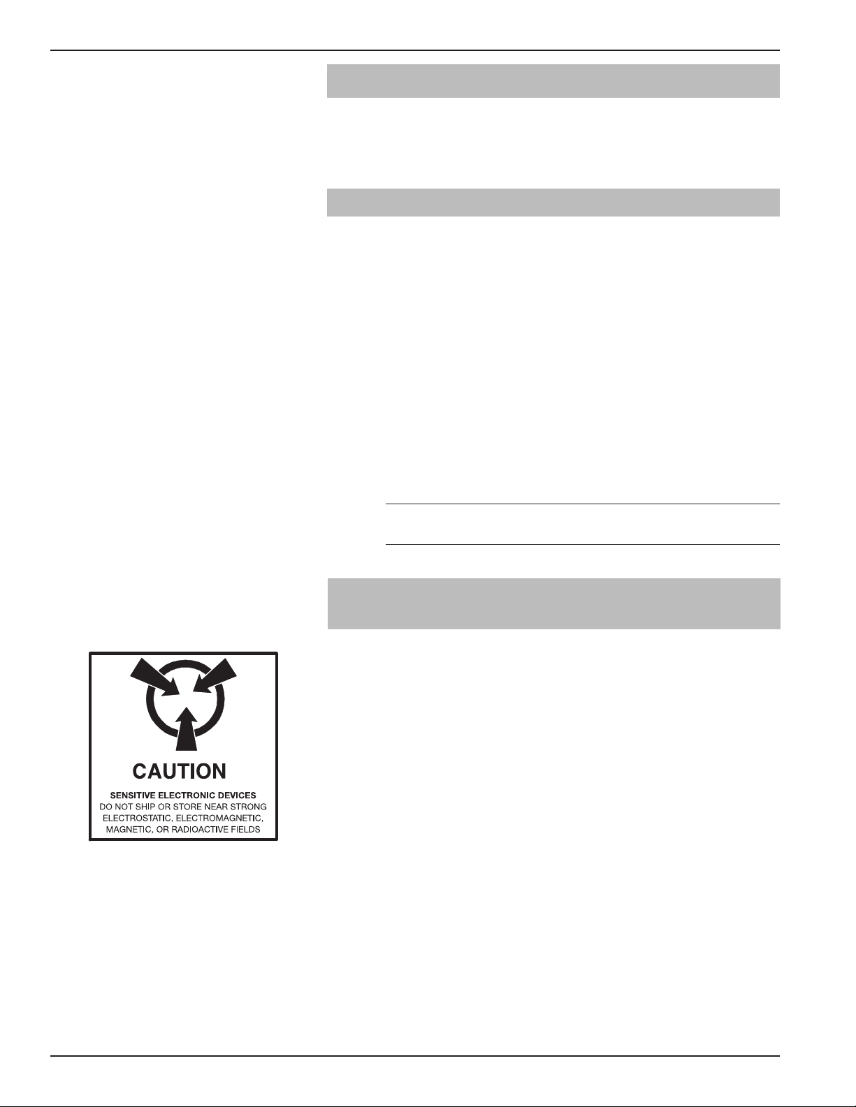
1.2.1 Probe
Carefully place the probe into the vessel. Align the probe
process connection with the threaded or flanged mounting
on the vessel.
5
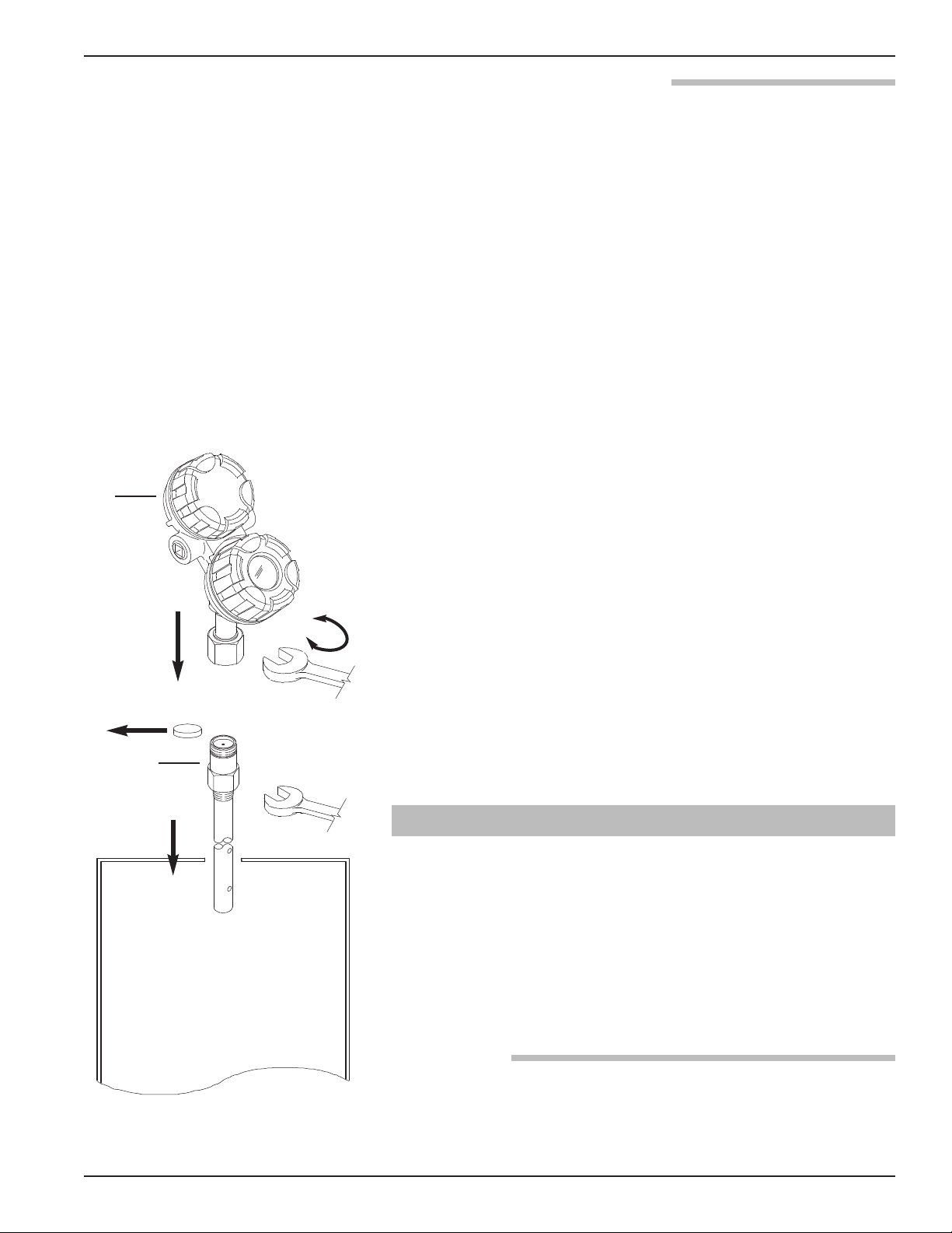
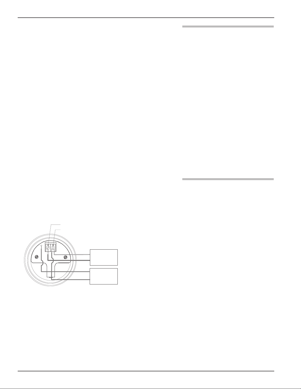
Page 6
1.2.2 Transmitter
Red (+)Black (-)
(+)
(-)
Tighten the hex nut of the probe process connection or
flange bolts.
NOTE: Leave the plastic protective cap in place until ready to
install the transmitter. Do not use sealing compound or TFE
tape on probe connection to transmitter as this connection is
sealed by a Viton®O-ring.
Remove the protective plastic cap from the top of the probe
and store for future use. Make sure the top probe connector
(female socket) is clean and dry. Clean with isopropyl
alcohol and cotton swabs if necessary.
Place the transmitter on the probe. Align the universal
connection at the base of the transmitter housing with the
top of the probe. Hand-tighten the connection.
Rotate the transmitter so that it is in the most convenient
position for wiring, configuring, and viewing.
Using a 1
1
⁄2" (38 mm) wrench, tighten the universal con-
nection on the transmitter1⁄4 to1⁄2 turn beyond hand-tight.
A torque wrench is highly recommended to obtain
45 ft-lbs. This is a critical connection. DO NOT LEAVE
HAND-TIGHT.
NOTE: Universal connector can be supplied with lock screws for
applications with significant vibration. Contact factory for
additional information.
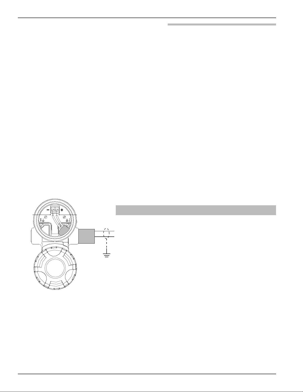
1.3 QuickStart Wiring
WARNING! Explosion hazard. Do not connect or disconnect equip-
ment unless power has been switched off or the area is
known to be non-hazardous.
NOTE: Ensure that the electrical wiring to the ECLIPSE transmitter is
complete and in compliance with all regulations and codes.
1. Remove the cover of the upper wiring compartment of the
transmitter.
2. Attach a conduit fitting and mount the conduit plug in the
spare opening. Pull the power supply wire through the conduit fitting.
3. Connect shield to an earth ground at power supply.
4. Connect an earth ground to the nearest green ground screw.
(Not shown in illustration.)
5. Connect the positive supply wire to the (+) terminal and the
negative supply wire to the (-) terminal. For Explosion
Proof Installations, see Wiring, Section 2.5.3.
6. Replace the cover and tighten.
6
57-600 Eclipse®Guided Wave Radar Transmitter
Page 7
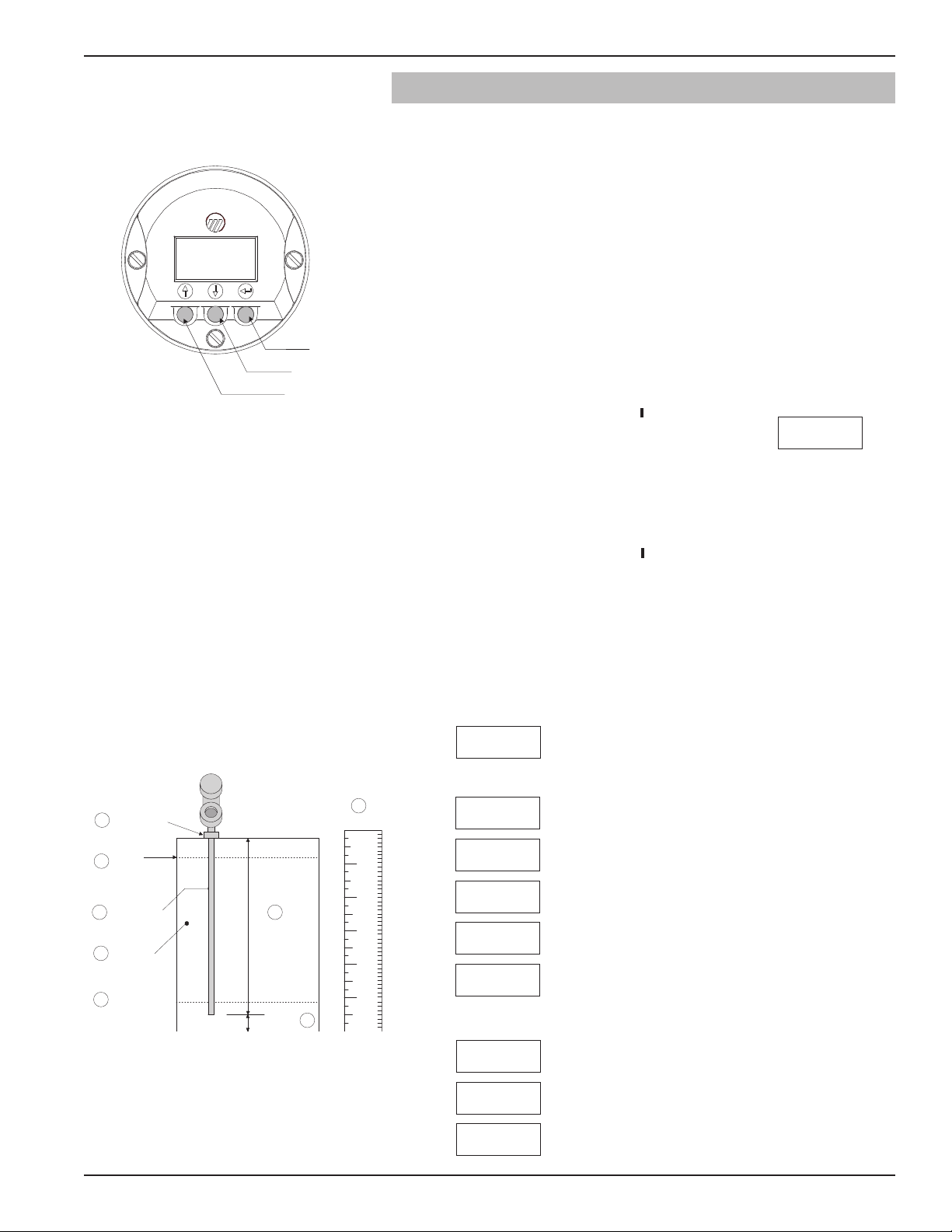
1.4 QuickStart Configuration
Level Offset
Probe Length
Probe Mount
4 mA Level
(0%-point)
Probe Model
Dielectric
of Medium
In or Cm
20 mA
(100% Point)
8
2
6
7
5
4
1
9
Enter
Down
Up
The ECLIPSE transmitter comes configured with default
values from the factory but can be reconfigured in the shop
(disregard any fault messages due to unattached probe). The
minimum configuration instructions required in the field
follow. Use the information from the operating parameters
table in Section 1.1.2 before beginning configuration.
1. Power up the transmitter.
The display changes every 5 seconds to show one of four
values: Status, Level, %Output, and Loop current.
NOTE: A small transition zone (0–6")
may exist at the top and bottom
of the probe. See Specifications,
Section 3.6.
57-600 Eclipse®Guided Wave Radar Transmitter
2. Remove the cover of the lower electronic compartment.
3. Use the Up or Down Arrow ( ) keys to move from one
step of the configuration program to the next step.
4. Press the Enter Arrow ( ) key. The last
character in the first line of the display
LvlUnits!
xxx
changes to an exclamation point (!).
5. Use the Up or Down Arrow ( ) keys to increase or
decrease the value in the display or to scroll through the
choices.
6. Press the Enter Arrow ( ) key to accept a value and move
to the next step of the configuration program (the default
password is 0).
7. After entering the last value, allow 10 seconds before
removing power from the transmitter.
The following configuration entries are the minimum required for
configuration (the default password is 0 from the LCD/keypad).
PrbModel
(select)
PrbMount
(select)
MeasType
(select)
Lvl Units
xxx
Probe Ln
xxx.x
LvlOfst
xxx.x
Dielctrc
(select)
Set 4mA
xxx.x
Set 20mA
xxx.x
Select the Probe Model to be used
Model 705: 7xA-x, 7xB-x, 7xD-x, 7xE-x, 7xF-F, 7xF-P,
7xF-4, 7xF-x, 7xJ-x, 7xK-x, 7xP-x, 7xR-x, 7xS-x,
7xT-x, 7x1-x, 7x2-x, 7x5-x, 7x7-x
Select the type of Probe Mounting to vessel (NPT, BSP,
or flange).
Select from Level Only, Level and Volume, Interface Level
or Interface Level and Volume.
Select the Units of measurement for the level readout (inches,
cm, feet or meters). Not included on Model 705 Fieldbus.
Enter the exact Probe Length as printed on the probe
nameplate.
Enter the Level Offset value. Refer to Section 2.6.6 for
further information. (The unit is shipped from the factory
with offset = 0; i.e., all measurements are referenced to
the bottom of the probe).
Enter the Dielectric range for the material to be measured.
Enter the level value (0%-point) for the 4 mA point.
Enter the level value (100%-point) for the 20 mA point.
7
Page 8
2.0 Complete Installation
This section provides detailed procedures for properly
installing and configuring the ECLIPSE Guided Wave
Radar Level Transmitter.
2.1 Unpacking
Unpack the instrument carefully. Make sure all components
have been removed from the packing material. Check all the
contents against the packing slip and report any discrepancies to the factory.
Before proceeding with the installation, do the following:
• Inspect all components for damage. Report any damage to
the carrier within 24 hours.
• Make sure the nameplate model number on the probe and
transmitter agree with the packing slip and purchase order.
• Record the model and serial numbers for future reference
when ordering parts.
Model Number
Serial Number
2.2 Electrostatic Discharge (ESD) Handling Procedure
Magnetrol
®
electronic instruments are manufactured to the
highest quality standards. These instruments use electronic
components that may be damaged by static electricity present in most work environments.
The following steps are recommended to reduce the risk of
component failure due to electrostatic discharge.
• Ship and store circuit boards in anti-static bags. If an antistatic bag is not available, wrap the board in aluminum foil.
Do not place boards on foam packing materials.
• Use a grounding wrist strap when installing and removing
circuit boards. A grounded workstation is recommended.
• Handle circuit boards only by the edges. Do not touch
components or connector pins.
• Make sure that all electrical connections are completely
made and none are partial or floating. Ground all equipment to a good, earth ground.
8
57-600 Eclipse®Guided Wave Radar Transmitter
Page 9

2.3 Before You Begin
2.3.1 Site Preparation
Each ECLIPSE transmitter is built to match the specific
physical specifications of the required installation. Make
sure the probe connection is correct for the threaded or
flanged mounting on the vessel or tank where the transmitter will be placed. See Mounting, Section 2.4.
Make sure that the wiring between the power supply and
ECLIPSE transmitter are complete and correct for the type
of installation. See Specifications, Section 3.6.
When installing the ECLIPSE transmitter in a general purpose
or hazardous area, all local, state, and federal regulations and
guidelines must be observed. See Wiring, Section 2.5.
2.3.2 Equipment and Tools
No special equipment or tools are required to install the
ECLIPSE transmitter. The following items are recommended:
• Open-end wrenches or adjustable wrench to fit the process
1
connection size and type. Coaxial probe 1
7
rod probe 1
⁄8" (47 mm), transmitter 11⁄2" (38 mm). A torque
⁄2" (38 mm), twin
wrench is highly desirable.
• Flat-blade screwdriver
• Digital multimeter or digital volt/ammeter
• 24 VDC power supply, 23 mA
2.3.3 Operational Considerations
Operating specifications vary based on Probe model
number. See Specifications, Section 3.6.
2.4 Mounting
The ECLIPSE transmitter can be mounted to a tank using
a variety of process connections. Generally, either a threaded
or flanged connection is used. For information about the
sizes and types of connections available, see Probe Model
Numbers, Section 3.7.2.
57-600 Eclipse®Guided Wave Radar Transmitter
NOTE: Do not place insulating material around any part of the
ECLIPSE transmitter as this may cause excessive heat buildup.
Make sure all mounting connections are properly in place
on the tank before installing the probe. Compare the nameplate on the probe and transmitter with the product information; make sure the ECLIPSE probe is correct for the
intended installation.
9
Page 10
WARNING! The Model 7xD, 7xR or 7xT overfill probes should be
used for Safety Shutdown/Overfill applications. All other
Guided Wave Radar probes should be installed so the
maximum overfill level is a minimum of 6" (150 mm)
below the process connection. This may include utilizing
a nozzle or spool piece to raise the probe. Consult
factory to ensure proper installation.
WARNING! Do not disassemble probe when in service and under
pressure.
2.4.1 Installing a Coaxial Probe (Models 7xA, 7xD, 7xG, 7xP, 7xR, 7xS, and 7xT)
Before installing, make sure the:
• Model and serial numbers on the nameplates of the
ECLIPSE probe and transmitter are identical.
• Probe has adequate room for installation and has unobstructed entry to the bottom of the vessel. The Model 7xD
(High Temp./High Pressure) probe, Model 7xP (High
Pressure) probe, Model 7xR (Overfill) probe, Model 7xS
(Steam) probe and Model 7xT (Interface) probe require
added clearance. See Physical Specifications, Section 3.6.6.
• Process temperature, pressure, dielectric, and viscosity are
within the probe specifications for the installation.
See Specifications, Section 3.6.
• Model 7xD (High Temp./High Pressure) probes should be
handled with extra care due to the ceramic spacers used
throughout their length.
• Model 7xG (caged GWR) probes should be handled
with extra care. Only handle these probes by the flanges.
2.4.1.1 To install a coaxial probe:
Make sure the process connection is at least3⁄4" NPT or a
flanged mounting.
Carefully place the probe into the vessel. Align the gasket
on flanged installations.
Align the probe process connection with the threaded or
flanged mounting on the vessel.
For threaded connections, tighten the hex nut of the probe
process connection. For flanged connections, tighten flange
bolts.
10
NOTE: If the transmitter is to be installed at a later time, do not remove
the protective cap from the probe. Do not use sealing compound or TFE tape on probe connection to transmitter as this
connection is sealed by a Viton®O-ring.
NOTE: For applications using the Model 7xS steam probe, it is manda-
tory to keep the transmitter and probe matched as a set.
57-600 Eclipse®Guided Wave Radar Transmitter
Page 11
2.4.2 Installing a Twin Rod Probe
Active
probe rod
Inactive
probe rod
(Models 7xB, 7x5, and 7x7)
Before installing, make sure the:
• Model and serial numbers on the nameplates of the
ECLIPSE probe and transmitter are identical.
• Probe has adequate headroom for installation and has unobstructed entry to the bottom of the vessel.
• Process temperature, pressure, dielectric, viscosity, and
media buildup are within the probe specifications for the
installation. See Specifications, Section 3.6.
Nozzles:
The 7xB/7x5/7x7 Twin Rod probes may be susceptible to
objects that are in close proximity. The following rules
should be followed for proper application:
1. Nozzles should be 3" (80 mm) diameter or larger.
2. 7xB/7x5/7x7 Twin Rod probes should be installed such that
the active rod is >1" (25 mm) from metallic objects such as
pipes, ladders, etc., (a bare tank wall parallel to the probe is
acceptable).
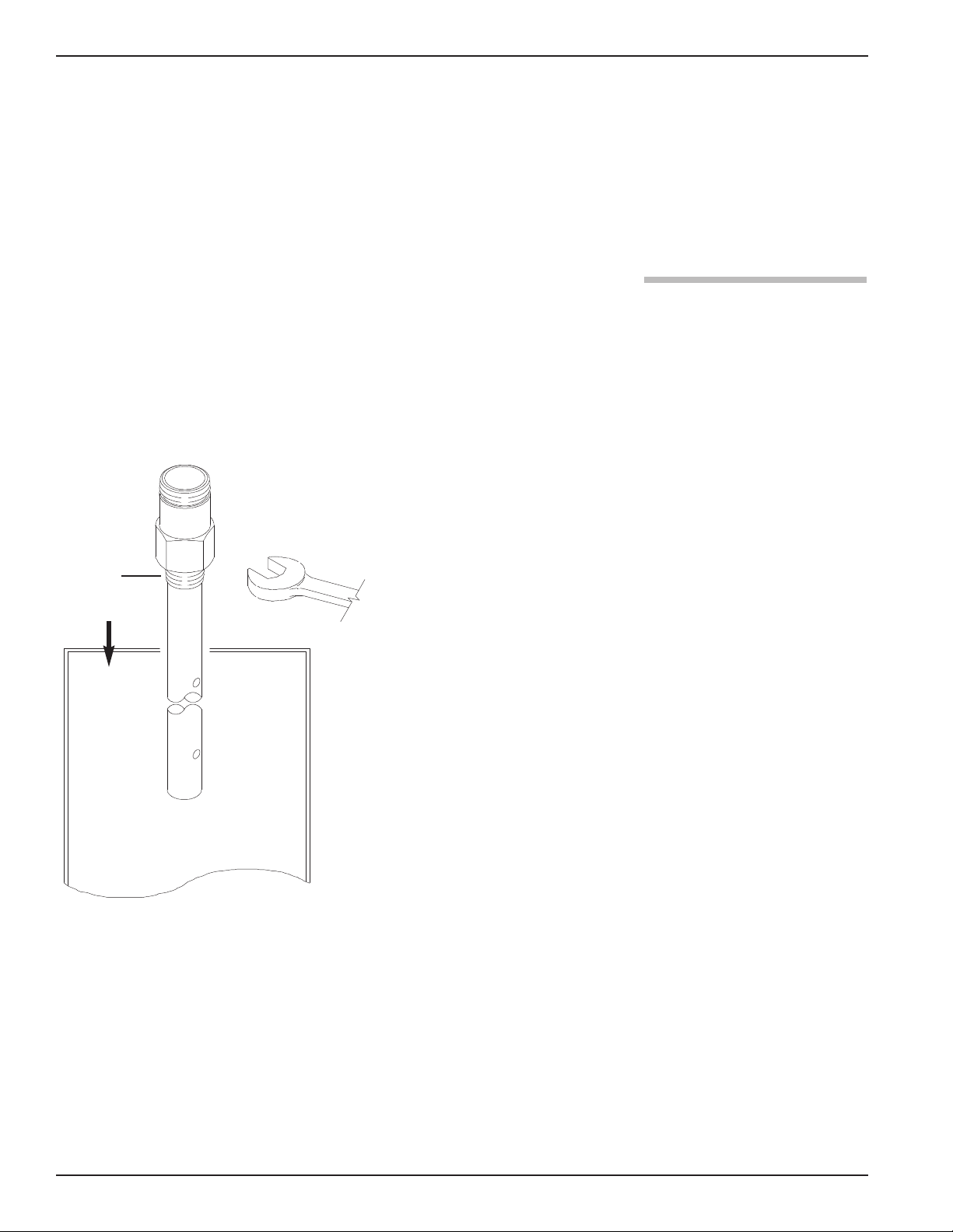
2.4.2.1 To install a rigid twin rod probe:
Make sure the process connection is at least 2" NPT or a
flanged mounting.
Make sure that there is at least 1" (25 mm) spacing between
the active probe rod and any part of the tank (walls, stillwell, pipes, support beams, mixer blades, etc.). Minimum
stillwell diameter for Twin Rod probe is 3".
Carefully place the probe into the vessel. Align the gasket
on flanged installations.
Align the probe process connection with the threaded or
flanged mounting on the vessel.
For threaded connections, tighten the hex nut of the probe
process connection. For flanged connections, tighten flange
bolts.
Probe can be stabilized by attaching the inactive probe rod
to vessel.
NOTE: If the transmitter is to be installed at a later time, do not remove
the protective cap from the probe. Do not use sealing compound or TFE tape on probe connection to transmitter as this
connection is sealed by a Viton®O-ring.
57-600 Eclipse®Guided Wave Radar Transmitter
11
Page 12
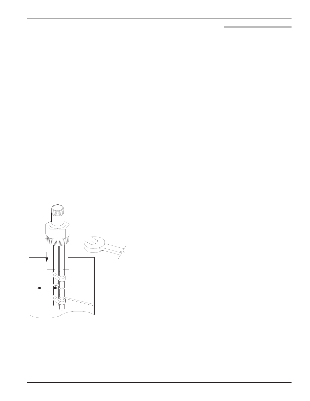
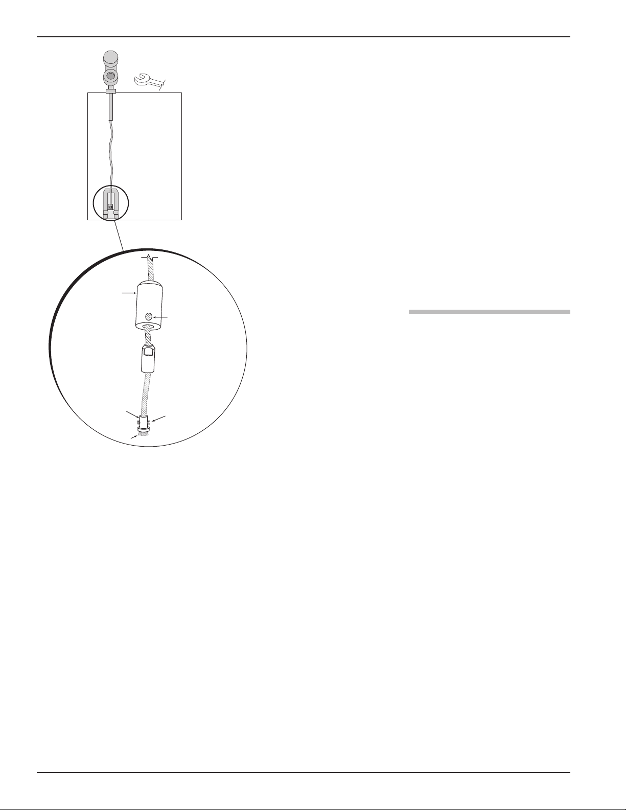
2.4.2.2 To install a Model 7x7 standard flexible twin rod probe:
0.50" (13 mm) Ø
1
3
2
4
➀
➁
➅
➅
➂
➃➄
Make sure the process connection is at least 2" NPT or a
flanged mounting.
Make sure that there is at least 1" (25 mm) spacing between
the active probe rod and any part of the tank (walls, stillwell, pipes, support beams, mixer blades, etc.). Minimum
stillwell diameter for Twin Rod probe is 3".
Carefully place the probe into the vessel. Align the gasket
on flanged installations.
Align the probe process connection with the threaded or
flanged mounting on the vessel.
For threaded connections, tighten the hex nut of the probe
process connection. For flanged connections, tighten flange
bolts.
Probe can be shortened in the field:
a. Raise the weight (1) to expose the two securing devices (2).
b. Loosen the two #10-32 set screws (3) on both securing
3
devices using a
⁄32" (2.5 mm) hex wrench and slide the
securing devices off of the probe.
c. Slide the TFE weight off of the probe.
d. Cut and remove the required cable (4) length.
1
e. Remove 3
⁄2" of the rib between the two cables.
f. Strip5⁄8" (16 mm) of coating from the two cables.
g. Slide the TFE weight back on to the probe.
h. Reattach securing device and tighten screws.
i. Enter new probe length (inches or cm) in software.
2.4.3 Installing a Single Rod Probe (Models 7x1, 7x2, 7xF, 7xJ)
Before installing, make sure the:
• Model and serial numbers on the nameplates of the
ECLIPSE probe and transmitter are identical.
• Probe has adequate headroom for installation and has unobstructed entry to the bottom of the vessel.
• Process temperature, pressure, dielectric, viscosity, and
media buildup are within the probe specifications for the
installation. See Specifications, Section 3.6.
• Nozzle does not restrict performance by ensuring the
following:
12
1. No nozzle is <2" (50mm) diameter.
57-600 Eclipse®Guided Wave Radar Transmitter
Page 13
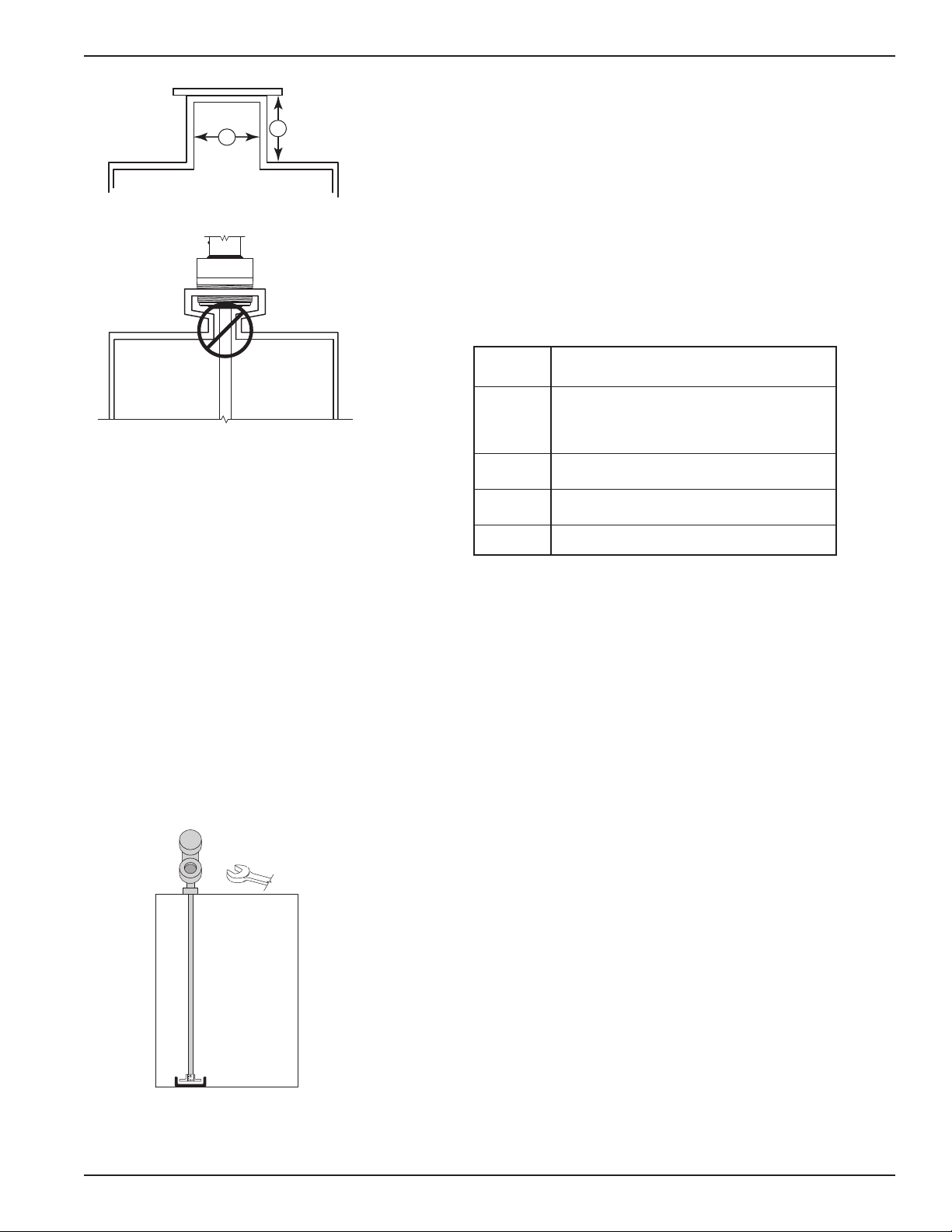
2. Ratio of Diameter: Length (A:B) is 1:1 or greater; any
A
B
➄
➀
➁
➂
➃
ratio <1:1 (e.g., a 2"× 6" nozzle = 1:3) may require a
Blocking Distance and/or DIELECTRIC adjustment
(see Section 2.6.5.2 Measurement Type: Level and
Volume).
3. No pipe reducers (restrictions) are used.
• Probe is kept away from conductive objects to ensure proper
performance. See Probe Clearance Table below. A lower gain
(increase in DIELECTRIC setting) may be necessary to
ignore certain objects (see Section 2.6.5.4 Measurement
Type: Interface and Volume).
PROBE CLEARANCE TABLE
Distance
to Probe Acceptable Objects
<6" Continuous, smooth, parallel conductive
>6" <1" (25mm) diameter pipe and beams,
>12" <3" (75mm) diameter pipe and beams,
>18" All remaining objects
2.4.3.1 To install a Model 7xF rigid single rod probe:
surface, for example a metal tank wall;
important that probe does not touch wall
ladder rungs
concrete walls
Make sure the process connection is at least 2" NPT or a
flanged mounting.
Carefully place the probe into the vessel. Align the gasket
on flanged installations.
Align the probe process connection with the threaded or
flanged mounting on the vessel.
For threaded connections, tighten the hex nut of the probe
process connection. For flanged connections, tighten flange
bolts.
Probe can be stabilized by placing into a non-metallic cup
or bracket at the bottom of the probe. A TFE bottom
spacer (P/N 89-9114-001) is optional for mounting into
a metallic cup or bracket.
57-600 Eclipse®Guided Wave Radar Transmitter
NOTE: If the transmitter is to be installed at a later time, do not remove
the protective cap from the probe. Do not use sealing compound or TFE tape on probe connection to transmitter as this
connection is sealed by a Viton®O-ring.
2.4.3.2 To install a Model 7x1 flexible single rod probe:
Make sure the process connection is at least 2" NPT or a
flanged mounting.
Carefully place the probe into the vessel. Align the gasket
on flanged installations.
13
Page 14
Align the probe process connection with the threaded or
1
0.50" (13 mm) Ø
2
3
4
➄
➀
➁
➂
➃
➅
flanged mounting on the vessel.
For threaded connections, tighten the hex nut of the probe
process connection. For flanged connections, tighten flange
bolts.
Probe can be shortened in field:
a. Raise TFE weight (1) exposing securing device (2).
3
b. Loosen both #10–32 set screws (3) using
⁄32" (2.5 mm)
hex wrench and remove securing device.
c. Cut and remove needed cable (4) length.
d. Reattach securing device and tighten screws.
e. Enter new probe length (inches or cm) in software.
Probe can be attached to the tank bottom using the
0.50" (13 mm) ∅ hole provided in the TFE weight.
Cable tension should not exceed 20 lbs.
2.4.4 Installation Guidelines Models 7x2/7x5 Bulk Solids Probes
The Model 7x2 and 7x5 Bulk Solids probes are designed for
a 3000 lb. (1360 kg) pull-down force for use in applications
such as sand, plastic pellets and grains. It is offered with a
maximum 75-foot (22-meter) probe length.
Model 7x2 Single Rod — dielectric ≥4
Model 7x5 Twin Rod — dielectric ≥1.9
NOTE: Avoid cement, heavy gravel, etc.
2.4.4.1 Applications
1. Plastic pellets, sugar: Dielectric constant 1.9-2.0
2. Grain, seeds, sand: Dielectric constant 2.0-3.0
3. Salts: Dielectric constant 4.0-7.0
4. Metallic powder, coal dust: Dielectric constant >7
2.4.4.2 Mounting recommendations
1. Use a weight instead of securing the probe to the vessel.
2. Mount probe at least 12 inches from the wall. Ideal
1
location is
of repose.
⁄4 to1⁄6 the diameter to average the angle
3. A metal flange must be used when mounting on plastic
vessels.
14
2.4.4.3 To install a Model 7x5 bulk solids flexible twin rod probe:
Make sure the process connection is at least 2" NPT or a
flanged mounting.
57-600 Eclipse®Guided Wave Radar Transmitter
Page 15
Make sure that there is at least 1" (25 mm) spacing
between the active probe rod and any part of the tank
(walls, stillwell, pipes, support beams, mixer blades, etc.).
Minimum stillwell diameter for Twin Rod probe is 3".
Carefully place the probe into the vessel. Align the gasket
on flanged installations.
Align the probe process connection with the threaded or
flanged mounting on the vessel.
For threaded connections, tighten the hex nut of the probe
process connection. For flanged connections, tighten flange
bolts.
Refer to Bulk Solid Guidelines, Section 2.4.4.
Probe can be shortened in the field:
a. Loosen and remove the two cable clamps.
b. Slide the weight off of the probe.
c. Cut the cable to the required length.
d. Remove 12 inches of the rib between the two cables.
Model 7x5 Dual Rod
Bulk Solids Probe
e. Strip 6 inches of coating from the two cables.
f. Slide the weight back on to the probe.
g. Reinstall the two cable clamps and tighten.
h. Enter the new probe length (inches or cm) in software.
2.4.4.4 To install a Model 7x2 bulk solids flexible single rod probe:
Make sure the process connection is at least 2" NPT or a
flanged mounting.
Carefully place the probe into the vessel. Align the gasket
on flanged installations.
Align the probe process connection with the threaded or
flanged mounting on the vessel.
For threaded connections, tighten the hex nut of the probe
process connection. For flanged connections, tighten flange
bolts.
Probe can be shortened in field:
a. Loosen and remove the two cable clamps.
b. Slide the weight off of the probe.
Model 7x2 Single Rod
Bulk Solids Probe
57-600 Eclipse®Guided Wave Radar Transmitter
c. Cut the cable to the required length plus 6.38".
d. Slide the weight back on to the probe.
e. Reinstall the two cable clamps and tighten.
f. Enter the new probe length (inches or cm) in software.
15
Page 16
2.4.5 Installing the Transmitter
The transmitter can be ordered for installation as an
Integral or Remote configuration.
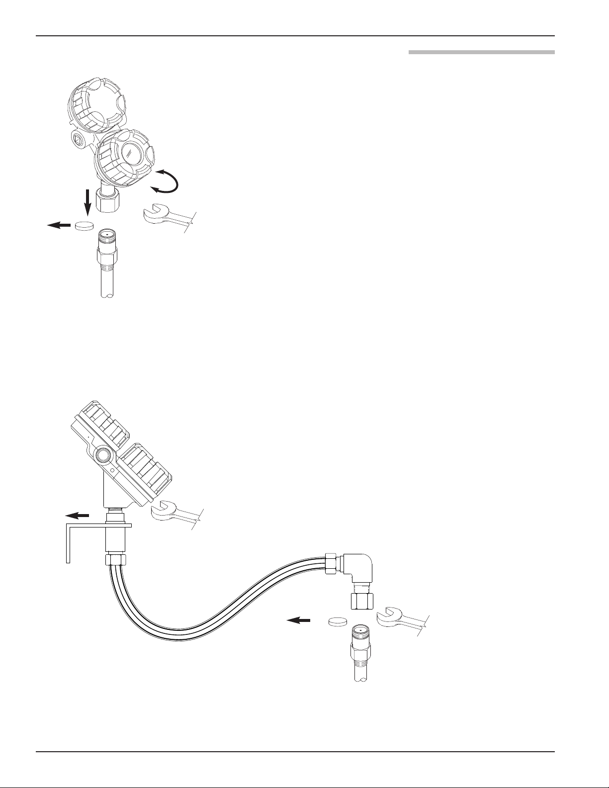
2.4.5.1 Integral Mount
Remove the protective plastic cap from the top of the
probe. Store the cap in a safe place in case the transmitter
has to be removed later.
Place the transmitter on the probe. Be careful not to bend
probe. Do not allow the gold, high frequency (male) connector to get dirty.
Align the universal connection at the base of the transmitter
housing with the top of the probe. Hand-tighten the
connection.
Rotate the transmitter to face the most convenient direction
for wiring, configuration, and viewing.
When the transmitter is facing the desired direction, use a
1
⁄2" (38 mm) wrench to tighten the universal connection on
1
the transmitter to 45 ft-lbs. A torque wrench is highly recommended. This is a critical connection. DO NOT LEAVE
HAND-TIGHT.
2.4.5.2 Remote Mount
Mount the transmitter/remote bracket as an assembly within
33" or 144" (84 or 366 cm) of the probe. DO NOT
REMOVE TRANSMITTER FROM BRACKET.
Remove the protective plastic cap from the top of the
probe. Store the cap in a safe place in case the transmitter
has to be removed later.
16
Align the universal connection at the end of the remote
1
assembly with the top of the probe. Using a 1
⁄2" (38 mm)
wrench, tighten the universal connection on the transmitter
to 45 ft-lbs. A torque wrench is highly recommended. This is
a critical connection. DO NOT LEAVE HAND-TIGHT.
NOTE: Remote mounting is recommended for all cast 316 SS
enclosures due to their extra weight.
57-600 Eclipse®Guided Wave Radar Transmitter
Page 17

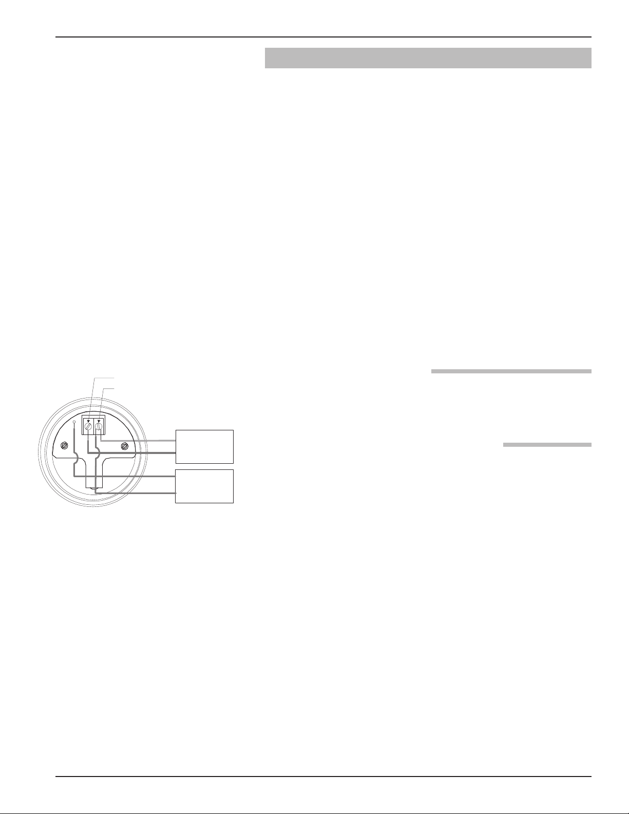
Red (+)Black (-)
(+)
(-)
2.5 Wiring
Caution: All HART versions of the ECLIPSE Model 705 transmitter
operate at voltages of 11–36 VDC. Higher voltage will
damage the transmitter.
Wiring between the power supply and the ECLIPSE
transmitter should be made using 18–22 AWG shielded
twisted pair instrument cable. Within the transmitter
enclosure, connections are made to the terminal strip
and the ground connections. The directions for wiring
the ECLIPSE transmitter depend on the application:
• General Purpose or Non-incendive (Cl I, Div. 2)
• Intrinsically Safe
• Explosion Proof
WARNING! Explosion hazard. Do not disconnect equipment unless
power has been switched off or the area is known to be
non-hazardous.
2.5.1 General Purpose or Non-Incendive (Cl I, Div. 2)
A general purpose installation does not have flammable
media present. Areas rated non-incendive (Cl I, Div. 2)
have flammable media present only under abnormal
conditions. No special electrical connections are required.
Wiring Diagram
Caution: If flammable media is contained in the vessel, the trans-
mitter must be installed per Cl I, Div. 1 standards of area
classification.
To install General Purpose or Non-Incendive wiring:
1. Remove the cover to the wiring compartment of the transmitter. Install the conduit plug in the unused opening.
Use PTFE tape/sealant to ensure a liquid-tight connection.
2. Install a conduit fitting and pull the supply wires.
3. Connect shield to an earth ground at power supply.
4. Connect an earth ground wire to the nearest green ground
screw (not shown in illustration).
5. Connect the positive supply wire to the (+) terminal and
the negative supply wire to the (-) terminal.
6. Replace the cover to the wiring compartment of the
transmitter.
57-600 Eclipse®Guided Wave Radar Transmitter
17
Page 18
2.5.2 Intrinsically Safe
Current Meter
+
–
Test
Current Meter
Power Supply
24 VDC
–
+
(-) negative
(+) positive
An intrinsically safe (IS) installation potentially has flammable media present. An approved IS barrier must be
installed in the non-hazardous (safe) area. See Agency
Drawing – Intrinsically Safe Installation, Section 3.4.2.
To install Intrinsically Safe wiring:
1. Make sure the IS barrier is properly installed in the safe
area (refer to local plant or facility procedures). Complete
the wiring from the barrier to the ECLIPSE transmitter.
2. Remove the cover to the wiring compartment of the transmitter. Install the conduit plug in the unused opening. Use
PTFE tape/sealant to ensure a liquid-tight connection.
3. Install a conduit fitting and pull the supply wires.
4. Connect shield to an earth ground at power supply.
5. Connect an earth ground wire to the nearest green ground
screw (not shown in illustration).
6. Connect the positive supply wire to the (+) terminal and
the negative supply wire to the (-) terminal.
7. Replace the cover to the wiring compartment of the
transmitter.
G.P./I.S./Explosion Proof Model
2.5.3 Explosion Proof
Explosion Proof (XP) is a method of designing equipment
for installation in hazardous areas. A hazardous location is
an area in which flammable gases or vapors are, or may be,
present in the air in quantities sufficient to produce explosive or ignitable mixtures. The wiring for the transmitter
must be contained in Explosion Proof conduit extending
into the safe area. Due to the specialized design of the
ECLIPSE transmitter, no Explosion Proof conduit fitting
(EY seal) is required within 18" of the transmitter. An
Explosion Proof conduit fitting (EY seal) is required
between the hazardous and safe areas. See Agency
Specifications, Section 3.4.1.
To install Explosion Proof wiring:
1. Install Explosion Proof conduit from the safe area to the
conduit connection of the ECLIPSE transmitter (refer to
local plant or facility procedures).
2. Remove the cover to the wiring compartment of the
transmitter.
3. Connect shield to an earth ground at the power supply.
4. Connect an Earth ground wire to the nearest green ground
screw per local electrical code (not shown in illustration).
18
5. Connect the positive supply wire to the (+) terminal and
the negative supply wire to the (-) terminal.
6. Replace the cover to the wiring compartment of the
transmitter before applying power.
57-600 Eclipse®Guided Wave Radar Transmitter
Page 19
2.6 Configuring the Transmitter
Current Meter
+
–
Test
Current Meter
Power Supply
24 VDC
–
+
(-) negative
(+) positive
The ECLIPSE transmitter comes configured from the factory
but can be reconfigured easily in the shop (disregard error
message due to unattached probe). Bench configuration
provides a convenient and efficient way to set up the
transmitter before going to the tank site to complete the
installation.
Before configuring the transmitter, collect the operating
parameters information (refer to Section 1.1.2). Power up
the transmitter on the bench and follow through the stepby-step procedures for the menu-driven transmitter display.
Information on configuring the transmitter using a HART
communicator is given in Configuration Using HART,
Section 2.7.
Information on configuring the transmitter using
OUNDATION fieldbus is given in Section 2.8.
F
Refer to instruction manual 57-640 for detailed
FOUNDATION fieldbus information.
G.P./I.S./Explosion Proof Model
2.6.1 Operating Parameters
Some key information is needed to calibrate the ECLIPSE
transmitter. Complete the configuration information table
in Section 1.1.2.
2.6.2 Setting Up for Bench Configuration
The ECLIPSE transmitter can be configured at a test
bench by connecting a 24 VDC power supply directly to
the transmitter terminals as shown in the accompanying
diagram. An optional digital multimeter is shown if current measurements are desired.
NOTE: Current measurements taken at these test points is an
approximate value. Accurate current readings should be
taken with the digital multimeter in series with the loop.
1. When using a HART communicator for configuration, a
minimum 250 Ω line load resistance is required. See the
HART communicator manual for more information.
2. The transmitter can be configured without the probe.
(Disregard the error message due to the unattached probe.)
3. After entering the last value, allow 10 seconds before
removing power from the transmitter. This allows the
transmitter to store values.
57-600 Eclipse®Guided Wave Radar Transmitter
19
Page 20
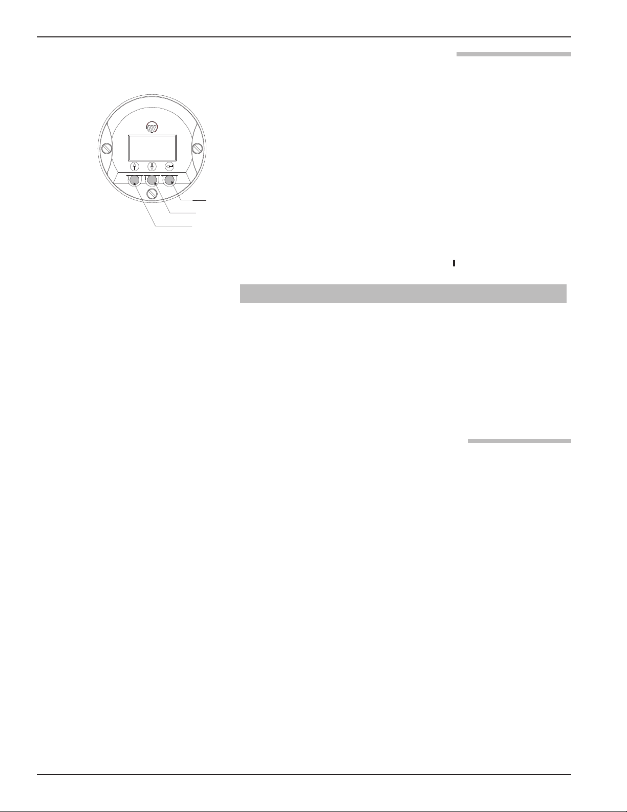
2.6.3 Transmitter Display and Keypad
Enter
Down
Up
The ECLIPSE transmitter has an optional liquid crystal display
(LCD) capable of showing two lines of 8 characters each.
Transmitter measurements and configuration menu screens
are shown on the LCD.
The transmitter default display is the measurement screen.
It cycles every 5 seconds to display STATUS, LEVEL,
%OUTPUT, and LOOP information (LEVEL,
%OUTPUT, and STATUS for Fieldbus version). The
transmitter defaults to this display after 5 minutes if no
keystrokes are sensed.
The keypad has three arrows used to scroll through the displays and to calibrate the transmitter. The Up and Down
Arrow ( ) keys and the Enter ( ) key.
Arrows Display Mode Configuration Mode
Up and Down Moves forward and backward Increases or decreases the
Enter Enters the configuration mode Accepts a value and moves
Function in Function in
in the configuration program value displayed or moves to
from one display to another. another choice.
NOTE: Hold arrow key for
rapid scrolling.
(noted by an exclamation point to the next step of the
as the last character in the top configuration program.
display line).
2.6.4 Password Protection (Default = 0)
The ECLIPSE transmitter is password protected to restrict
access to certain portions of the menu structure that affect
the operation of the system. When the proper password is
entered, an exclamation point (!) appears as the last character of the first line of the display. The password can be
changed to any numerical value up to 255. The password is
required whenever configuration values are changed.
The default user password installed in the transmitter at the
factory is 0. The last step in the configuration menu provides the option to enter a new password. With a password
of 0, the transmitter is no longer password protected and
any value in the menu can be adjusted without entering a
confirming password, except diagnostic values.
20
NOTE: If the password is not known, the menu item New Password
displays an encrypted value representing the present password. Call the factory with this encrypted value to determine
the present password.
57-600 Eclipse®Guided Wave Radar Transmitter
Page 21

2.6.5 Model 705 Menu: Step-By-Step Procedure
The following tables provide a complete explanation of
the software menus displayed by the ECLIPSE transmitter.
Use these tables as a step-by-step guide to configure the
transmitter based on a desired measurement type of:
• Level Only, Section 2.6.5.1
• Level and Volume, Section 2.6.5.2
• Interface Level, Section 2.6.5.3
• Interface Level and Volume, Section 2.6.5.4
The tables are separated to display the parameters based
on the measurement type. The second column presents
the menus shown on the transmitter display. The displays
are in the order they would appear if the arrow keys were
used to scroll through the menu. The numbers in the first
column are not shown on the display. They are only provided as a reference.
The third column provides the actions to take when configuring the transmitter. Additional information or an
explanation of an action is given in the fourth column.
(Shaded sections are factory menu items).
2.6.5.1 Measurement Type: Level Only (Loop Control = Level)
Display Action Comment
1
2
3
4
5
6
7
8
9
10
11
*Status*
*Level *
*% Out *
* Loop *
Level
xxx.x
% Output
xx.x%
Loop
xx.xx mA
PrbModel
(select)
PrbMount
(select)
MeasType
(select)
LvlUnits
(select)
Probe Ln
xxx.x
Lvl Ofst
xxx.x
Dielctrc
(select)
Transmitter Display LoopCtrl = Level.
Transmitter default display showing Status, Level, % Output, and
Loop values cycles every 5 seconds
Transmitter Display Transmitter displays Level Value in selected units
Transmitter Display Transmitter displays % Output measurement derived from 20 mA
span
Transmitter Display Transmitter displays Loop value (mA)
Select the type of probe
used
(Example: 7xR-x)
Select the type of probe
mounting
Select type of measurement Select Lvl Only
Select level units Select from cm, inches, feet or meters
Enter the exact length of
probe
Enter the desired reading
when probe is dry
Select range bounding the
dielectric constant of the
media
Select from 7xA-x, 7xB-x, 7xD-x, 7xE-x, 7xF-x, 7xF-E, 7xF-F,
7xF-4, 7xG-x, 7xF-P, 7xG, 7xJ-x, 7xK-x, 7xL, 7xM, 7xN, 7xP-x,
7xR-x, 7xS-x, 7xT-x, 7x1-x, 7x2-x, 7x5-x, 7x7-x as shown on
the probe nameplate
Select from NPT, BSP, or Flange
Probe length is printed on the nameplate and order information
and is the last three digits of the probe model number
Level Offset is the distance from the probe tip to the desired 0
level point (-90 to 300"). Refer to Section 2.6.6
Select from 1.4–1.7; 1.7–3; 3–10; 10–100
57-600 Eclipse®Guided Wave Radar Transmitter
21
Page 22

2.6.5.1 Measurement Type: Level Only (Loop Control = Level)
Display Action Comment
12
13
14
15
16
17
18
19
20
21
22
23
24
25
26
Senstvty
xxx
LoopCtrl
(select)
Set 4mA
xxx.x 1u
Set 20mA
xxx.x lu
Damping
xx s
Fault
(select)
BlockDis
xx.x lu
SZ Fault
(select)
SZ Height
(xx.x lu)
SZ Alarm Reset
Threshld
(select)
Poll Adr
xx
Loop Mode
Trim Lvl
xx.x lu
Trim 4
xxxx
Enter value upward or
downward to sense liquid
Allows fine gain adjustment for single rod probes (this parameter
is password protected for coaxial and twin rod probes).
surface
Select variable to control
Select Level
loop current
Enter the PV value for the
4 mA point
Enter the PV value for the
20 mA point
A small transition zone (0–6") may exist at the top/bottom of
the probe. See Functional Specifications Probe, Section 3.6.1
A small transition zone (0–6") may exist at the top/bottom of
the probe. Top 4" (100 mm) of 7xB Twin Rod Probe is inactive.
See Functional Specifications Probe, Section 3.6.1
Enter time constant of
desired damping
Select the loop current value
A Damping factor (0–10 seconds) may be added to smooth the
output due to turbulence
Select from 3.6 mA, 22 mA or HOLD
in presence of a fault
Enter distance below reference point where level is not
Allows user to ignore level measurements near the top of the
probe
sensed
Select loop current behavior
when level is sensed in safety
zone
Safety Zone is a user-defined area just below the Blocking
Distance. Enable Fault if necessary to ensure safe, reliable high-
level readings in critical applications. Choices are None, 3.6 mA,
22 mA, Latch 3.6 or Latch 22. If Latch 3.6 or Latch 22 is
selected, the loop current will remain in alarm until it is manually
cleared with the SZ Alarm Reset below (#21)
Enter distance below
BlockDis where SZ Fault will
be asserted
Press Enter to clear a
Enter a distance value that develops a safety zone just below the
Blocking Distance. Here the unit will report a Safety Zone Fault
(#19) if the level rises into this area.
Clear a latched Safety Zone alarm
latched Safety Zone alarm
Select the type of threshold Unit default CFD. Only select Fixed in application with low
dielectric material over higher dielectric material and unit is reading incorrect level. Example: Oil over water. (Adjustment of Trim
Level may be necessary when threshold is changed)
Enter HART polling address
number (0-63)
Select a HART poll address (0–63). Enter 0 for a single
transmitter installation. Poll address does not affect loop current.
Enable/Disable Determines whether the loop is fixed at 4.0 mA or controlled by
the PV.
Enter value to adjust Level
reading
-10.0 inches ≤ Lvl Trim ≤ +10.0 inches
(Requires superuser password)
Fine tune the 4 mA point Adjust setting to output exactly 4.0 mA on current meter
22
27
28
29
30
31
32
Trim 20
xxxx
Loop Tst
xx.x mA
LvlTicks
Xxxxx
New Pass
xxx
Language
(select)
Mdl705HT
Ver3.0a0
Fine tune the 20 mA point Adjust setting to output exactly 20.0 mA on current meter
Enter a mA Output value Set mA output to any given value to perform loop test
Diagnostic Display Time of flight from fiducial to level signal
Enter new password (0-255) Displays encrypted value of present password
Select from English, Spanish,
Language choice for LCD display
French, German
Transmitter display Product identification Firmware version
57-600 Eclipse®Guided Wave Radar Transmitter
Page 23

2.6.5.1 Measurement Type: Level Only (Loop Control = Level)
Display Action Comment
33
34
(current status)
DispFact
(select)
History
Select Yes to display factory
parameter menus
Press Enter to view history
of exceptions
Diagnostic Display
35
36
37
38
39
40
41
42
43
44
45
46
Run Time
History Reset
HF cable
(select)
FidTicks
xxxx
FidSprd
Fid Type
(select)
Fid Gain
xxx
Window
xxx
Conv Fct
xxxx
Scl Ofst
xxx
Neg Ampl
xxx
Pos Ampl
xxx
Press Enter and select yes
Similar to SZ Alarm Reset
to clear history
Superuser Parameter Select from 3-foot or 12-foot remote
Diagnostic Display Time of flight from start of ramp to fiducial
Superuser Parameter Select from positive or negative
(Selection only allowed for some probes)
Superuser Parameter Amount of gain applied to the fiducial signal
Factory Parameter
Factory Parameter Calibration parameter
Factory Parameter Calibration parameter
Superuser Password Diagnostic parameter
Superuser Password Diagnostic parameter
47
48
49
50
51
52
53
54
55
56
57
58
Signal
xxx
Compsate
(select)
DrateFct
xxxx
Targ Ampl
xxxx
Targ Tks
xxxx
Targ Cal
xxxx
OperMode
(select)
7xKCorr
xxx
ElecTemp
xxx C
Max Temp
xxx C
Min Temp
xxx C
SZ Hyst
xx.x lu
Diagnostic Display Indication of level signal amplitude
Superuser Password Select from None, Manual, Auto
Diagnostic Display Compsate = Auto. Velocity derating factor for Model 7xS Steam
probe
Diagnostic Display Compsate = Auto. Indication of steam reference target amplitude
Diagnostic Display Compsate = Auto. Measured time of flight from fiducial to steam
reference target
Diagnostic Display Compsate = Auto. Calibrated time of flight from fiducial to target
in room temperature air
Superuser Password Compsate = Auto. Select from Run, Cal, Off
Superuser Password Distance in mm from fiducial to user reference point
(7xK probe characteristic)
Diagnostic Display Present temperature in electronics compartment
(degrees Celsius)
Superuser Password Maximum electronics temperature recorded
Superuser Password Minimum electronics temperature recorded
Superuser Password
57-600 Eclipse®Guided Wave Radar Transmitter
23
Page 24

2.6.5.2 Measurement Type: Level and Volume (Loop Control = Volume)
Display Action Comment
*Status*
1
*Volume*
*% Out *
* Loop *
Transmitter Display LoopCtrl = Volume
Transmitter default display showing: Status, Volume, % Output
and Loop values cycles every 5 seconds
2
3
4
5
6
7
8
9
10
11
12
Volume
xxx vu
% Output
xx.x%
Loop
xx.xx mA
Level
xxx.x 1u
PrbModel
(select)
PrbMount
(select)
MeasType
(select)
LvlUnits
(select)
Probe Ln
xxx.x lu
Lvl Ofst
xxx.x lu
VolUnits
(select)
Transmitter Display Transmitter displays Volume in selected units
Transmitter Display Transmitter displays % Output measurement derived from 20 mA
span
Transmitter Display Transmitter displays Loop value (mA)
Transmitter Display Transmitter displays Level Value in selected units
Select the type of probe
used
(Example: 7xR-x)
Select the type of probe
Select from 7xA-x, 7xB-x, 7xD-x, 7xE-x, 7xF-x, 7xF-E, 7xF-F,
7xF-4, 7xF-P, 7xG-x, 7xJ-x, 7xK-x, 7xL, 7xM, 7xN, 7xP-x, 7xR-x,
7xS-x, 7xT-x, 7x1-x, 7x2-x, 7x5-x, 7x7-x as shown on the probe
nameplate
Select from NPT, BSP, or Flange
mounting
Select type of measurement Select from Lvl&Vol
Select level units Select from cm, inches, feet or meters
Enter the exact length of
probe
Enter desired Level reading
when probe is dry
Probe length is printed on the nameplate and order information
and is the last three digits of the probe model number
Level Offset is the distance from the probe tip to the desired 0
level point (-90 to 300"). Refer to Section 2.6.6
Select the volume units Select from liters or gallons
13
14
15
16
17
18
19
20
21
StrapTbl
nn pnts
Dielctrc
(select)
Senstvty
xxx
LoopCtrl
(select)
Set 4mA
xxxx vu
Set 20mA
xxxx vu
Damping
xx s
Fault
(select)
BlockDis
xx.x lu
Enter to access strapping
table
Select range bounding the
dielectric constant of the
media
Enter value upward or
downward to sense liquid
surface
Select variable to control
loop current
Enter the PV value for the
4 mA point
Enter the PV value for the
20 mA point
Enter time constant of
desired damping
Select the loop current value
in presence of a fault
Enter distance below reference point where level is not
sensed
20-point strapping table enables conversion from level to volume
(Refer to Section 2.6.7 for more information)
Select from 1.4–1.7; 1.7–3; 3–10; 10–100
Allows fine gain adjustment for single rod probes (this parameter
is password protected for coaxial and twin rod probes)
Select from Level or Volume
A small transition zone (0–6") may exist at the top/bottom of
the probe. See Functional Specifications Probe, Section 3.6.1
A small transition zone (0–6") may exist at the top/bottom of
the probe
A Damping factor (0–10 seconds) may be added to smooth the
output due to turbulence
Select from 3.6 mA, 22 mA or HOLD
Allows user to ignore level measurements near the top of the
probe
24
57-600 Eclipse®Guided Wave Radar Transmitter
Page 25

2.6.5.2 Measurement Type: Level and Volume (Loop Control = Volume)
Display Action Comment
22
23
24
25
26
27
28
29
SZ Fault
(select)
SZHeight
xx.x lu
SZ Alarm Reset
Threshld
(select)
Poll Adr
xx
Loop Mode
Trim Lvl
xx.x lu
Trim 4
xxxx
Select loop current behavior
when level is sensed in safety
zone
Enter distance below
BlockDis where SZ Fault will
be asserted
Press Enter to clear a
latched Safety Zone alarm
Select the type of threshold Unit default CFD. Only select Fixed in application with low
Enter HART polling address
number (0-63)
Enable/Disable Determines whether the loop is fixed at 4.0 mA or controlled by
Enter value to adjust Level
reading
Fine tune the 4 mA point Adjust setting to output exactly 4.0 mA on current meter
Safety Zone is a user-defined area just below the Blocking
Distance. Enable Fault if necessary to ensure safe, reliable high-
level readings in critical applications. Choices are None, 3.6 mA,
22 mA, Latch 3.6 or Latch 22. If Latch 3.6 or Latch 22 is
selected, the loop current will remain in alarm until it is manually
cleared with the SZ Alarm Reset below (#23)
Enter a distance value that develops a safety zone just below the
Blocking Distance. Here the unit will report a Safety Zone Fault
(#21) if the level rises into this area.
Clear a latched Safety Zone alarm
dielectric material over higher dielectric material and unit is reading incorrect level. Example: Oil over water. (Adjustment of Trim
Level may be necessary when threshold is changed)
Select a HART poll address (0–63). Enter 0 for a single
transmitter installation. Poll address does not affect loop current.
the PV.
-10.0 inches <= Lvl Trim <= +10.0 inches
(Requires superuser password)
30
31
32
33
34
35
36
37
(current status)
38
39
40
History Reset
41
Trim 20
xxxx
Loop Tst
xx.x mA
LvlTicks
xxxx
New Pass
xxx
Language
(select)
Mdl705HT
Ver3.0a0
DispFact
(select)
History
HF cable
(select)
Run Time
FidTicks
xxxx
Fine tune the 20 mA point Adjust setting to output exactly 20.0 mA on current meter
Enter a mA Output value Set mA output to any given value to perform loop test
Diagnostic Display Time of flight from fiducial to level signal
Enter new password (0-255) Displays encrypted value of present password
Select from English, Spanish,
Language choice for LCD display
French, German
Transmitter display Product identification Firmware version
Select Yes to display factory
Allows for viewing the factory parameters
parameter menus
Press Enter to view history
Diagnostic Display
of recent exceptions
Superuser Parameter Select from 3-foot or 12-foot remote
Press Enter and select yes
Similar to SZ Alarm Reset
to clear history
Diagnostic Display Time of flight from start of ramp to fiducial
42
43
57-600 Eclipse®Guided Wave Radar Transmitter
Fid Type
(select)
Fid Spread
Superuser Password Select from positive or negative
(Selection only allowed for some probes)
25
Page 26

2.6.5.2 Measurement Type: Level and Volume (Loop Control = Volume)
Display Action Comment
44
Fid Gain
xxx
Superuser Password
45
46
47
48
49
50
51
52
53
54
55
Window
xxx
Conv Fct
xxxx
Scl Ofst
xxx
Neg Ampl
xxx
Pos Ampl
xxx
Signal
xxx
Compsate
(select)
7xKCorr
xxx
ElecTemp
xxx C
Max Temp
xxx C
Min Temp
xxx C
Factory Parameter
Factory Parameter Calibration parameter
Factory Parameter Calibration parameter
Superuser Password Diagnostic factory setting
Superuser Password Diagnostic factory setting
Diagnostic Display Indication of level signal amplitude
Superuser Parameter Select from None, Manual, Auto
Superuser Parameter Distance in mm from fiducial to user reference point
(7xK probe characteristic)
Diagnostic Display Present temperature in electronics compartment
(degrees Celsius)
Diagnostic Display Maximum electronics temperature recorded
Diagnostic Display Minimum electronics temperature recorded
56
SZ Hyst
xx.x lu
Diagnostic Display Diagnostic factory setting
26
57-600 Eclipse®Guided Wave Radar Transmitter
Page 27

2.6.5.3 Measurement Type: Interface Level (Loop Control = Interface Level)
Display Action Comment
*Status*
1
2
*IfcLvl*
*% Out *
* Loop *
IfcLvl
xxxx vu
Transmitter Display LoopCtrl = IfcLevel
Transmitter default display showing Status, IfcLevel, % Output,
and Loop values cycles every 5 seconds
Transmitter Display Transmitter displays interface level in selected units
3
4
5
6
7
8
9
10
11
12
% Output
xx.x%
Loop
xx.xx mA
Level
PrbModel
(select)
PrbMount
(select)
MeasType
(select)
LvlUnits
(select)
Probe Ln
xxx.x
Lvl Ofst
x.xx
Upr Diel
(select)
Transmitter Display Transmitter displays % Output measurement derived from
20 mA span
Transmitter Display Transmitter displays Loop value (mA)
Select the type of probe
used
Select from 7xB-x, 7xD-x, 7xF-x, 7xG, 7xL, 7xM, 7xN, 7xT-x,
7x7-x as shown on the probe nameplate
(Example: 7xT-x)
Select the type of probe
Select from NPT, BSP, or Flange
mounting
Select type of measurement Select from Intrface
Select level units Select from cm, inches, feet or meters
Enter the exact length of
probe
Enter the desired reading
when probe is dry
Enter the dielectric constant
Probe length is printed on the nameplate and order information
and is the last three digits of the probe model number
Level Offset is the distance from the probe tip to the desired 0%
level point (-90 to 300"). Refer to Section 2.6.6
Interface mode or Manual compensation mode
of the upper liquid
13
14
15
16
17
18
19
20
Dielctrc
(select)
Senstvty
xxx
LoopCtrl
(select)
Set 4mA
xxx.x 1u
Set 20mA
xxx.x lu
Damping
xx s
Fault
(select)
BlockDis
xx.x lu
Select range bounding the
dielectric constant of the
lower liquid
Enter value upward or
downward to sense liquid
surface
Select variable to control
loop current
Enter the PV value for the
4 mA point
Enter the PV value for the
20 mA point
Enter time constant of
desired damping
Select the loop current value
in presence of a fault
Enter distance below
reference point where
level is not sensed
Select 10–100
Allows fine gain adjustment for single rod probes (this parameter
is password protected for coaxial and twin rod probes)
Select from Level or IfcLvl
A small transition zone (0–6") may exist at the top/bottom of
the probe. See Functional Specifications Probe, Section 3.6.1
A small transition zone (0–6") may exist at the top/bottom of
the probe
A Damping factor (0–10 seconds) may be added to smooth the
output due to turbulence
Select from 3.6 mA, 22 mA or HOLD
Allows user to ignore level measurements near the top of probe
57-600 Eclipse®Guided Wave Radar Transmitter
27
Page 28

2.6.5.3 Measurement Type: Interface Level (Loop Control = Interface Level)
Display Action Comment
21
SZ Fault
(select)
Select loop current behavior
when level is sensed in safety
zone
Safety Zone is a user-defined area just below the Blocking
Distance. Enable Fault if necessary to ensure safe, reliable high-
level readings in critical applications. Choices are None, 3.6 mA,
22 mA, Latch 3.6 or Latch 22. If Latch 3.6 or Latch 22 is
selected, the loop current will remain in alarm until it is manually
cleared with the SZ Alarm Reset below (#23)
22
23
24
25
26
27
28
29
30
31
32
SZ Height
xx.x lu
SZ Alarm Reset
Threshld
(select)
IfcThrsh
(select)
Poll Adr
xx
Loop Mode
Trim Lvl
xx.x lu
Trim 4
xxxx
Trim 20
xxxx
Loop Tst
xx.x mA
LvlTicks
xxxx
Enter distance below
BlockDis where SZ Fault will
be asserted
Press Enter to clear a
Enter a distance value that develops a safety zone just below the
Blocking Distance. Here the unit will report a Safety Zone Fault
(#21) if the level rises into this area.
Clear a latched Safety Zone alarm
latched Safety Zone alarm
Select from CFD, Fixed For interface, refers to threshold for upper level pulse. (Set to
Fixed for most common applications.)
Select from CFD, Fixed Interface mode only. Threshold for interface level pulse. (Set to
CFD for most common applications.)
Enter HART polling address
number (0-63)
Select a HART poll address (0–63). Enter 0 for a single
transmitter installation. Poll address does not affect loop current.
Enable/Disable Determines whether the loop is fixed at 4.0 mA or controlled by
the PV.
Enter value to adjust Level
reading
-10.0 inches <= Lvl Trim <= +10.0 inches
(Requires superuser password)
Fine tune the 4 mA point Adjust setting to output exactly 4.0 mA on current meter
Fine tune the 20 mA point Adjust setting to output exactly 20.0 mA on current meter
Enter a mA Output value Set mA output to any given value to perform loop test
Diagnostic Display Time of flight from fiducial to interface signal
33
34
35
36
37
38
39
(current status)
40
41
History Reset
42
IfcTicks
xxxx
Medium
New Pass
xxx
Language
(select)
Mdl705HT
Ver3.0a0
DispFact
(select)
History
Run Time
HF cable
(select)
Diagnostic Display Interface mode only. Time of flight through upper liquid
Diagnostic Display Interface mode only. Displayed messages are: Unknown,
Oil Only, Thin Oil, Thick Oil, Dry Probe
Enter new password (0-255) Displays encrypted value of present password
Select from English, Spanish,
Language choice for LCD display. (no HART counterpart)
French, German
Transmitter display Product identification. Firmware version
Select Yes to display factory
Access for viewing the factory parameter
parameter menus
Press Enter to view history
Diagnostic Display
of recent exceptions
Press Enter and select yes
Similar to SZ Alarm Reset
to clear history
Superuser Parameter Select from 3-foot or 12-foot remote
28
57-600 Eclipse®Guided Wave Radar Transmitter
Page 29

2.6.5.3 Measurement Type: Interface Level (Loop Control = Interface Level)
Display Action Comment
43
FidTicks
xxxx
Diagnostic Display Time of flight from start of ramp to fiducial
44
45
46
47
48
49
50
51
52
53
54
Fid Sprd
xxx
Fid Type
(select)
Fid Gain
xxx
Window
xxx
Conv Fct
xxxx
Scl Ofst
xxx
Neg Ampl
xxx
Ifc Ampl
Pos Ampl
xxx
Signal
xxx
Compsate
Diagnostic Display Spread in fiducial ticks readings
Superuser Parameter Select from positive or negative
(Selection only allowed for some probes)
Superuser Parameter Amount of gain applied to fiducial signal
Factory Parameter
Factory Parameter Calibration parameter
Factory Parameter Calibration parameter
Superuser Password
Superuser Password
Superuser Password
Diagnostic Display Indication of level signal amplitude
Superuser Parameter Select from None, Manual, Auto
55
56
57
58
59
7xKCorr
xxx
ElecTemp
xxx C
Max Temp
xxx C
Min Temp
xxx C
SZ Hyst
xx.x lu
Superuser Parameter Distance in mm from fiducial to user reference point
(7xK probe characteristic)
Diagnostic Display Present temperature in electronics compartment
(degrees Celsius)
Superuser Password Maximum electronics temperature recorded
Superuser Password Minimum electronics temperature recorded
Superuser Parameter Safety Zone hysteresis height
57-600 Eclipse®Guided Wave Radar Transmitter
29
Page 30

2.6.5.4 Measurement Type: Interface and Volume
Display Action Comment
*Status*
1
2
*IfcLvl*
*% Out *
* Loop *
IfcLevel
xxx.x lu
Transmitter Display LoopCtrl = IfcLevel and Volume
Transmitter default display showing Status, Interface Level,
Volume, % Output, and Loop values cycles every 5 seconds
Transmitter Display LoopCtrl = IfcLevel
3
4
5
6
7
8
9
10
11
12
13
14
15
16
Ifc Vol
xxxx vu
% Output
xx.x%
Loop
xx.xx mA
Level
Volume
PrbModel
(select)
PrbMount
(select)
MeasType
(select)
LvlUnits
(select)
Probe Ln
xxx.x lu
Lvl Ofst
xxx.x lu
VolUnits
(select)
StrapTbl
nn pnts
Upr Diel
(select)
Transmitter Display LoopCtrl = Ifc Vol
Transmitter Display Transmitter displays % Output measurement derived from
20 mA span
Transmitter Display Transmitter displays Loop value (mA)
Select the type of probe
used
Select from 7xB-x, 7xD-x, 7xF-x, 7xG, 7xL, 7xM, 7xN, 7xT-x,
7x7-x as shown on the probe nameplate
(Example: 7xT-x)
Select the type of probe
Select from NPT, BSP, or Flange
mounting
Select type of measurement Select from Ifc&Vol
Select level units Select from cm, inches, feet or meters
Enter the exact length of
probe
Enter the desired reading
when probe is dry
Probe length is printed on the nameplate and order information
and is the last three digits of the probe model number
Offset is the distance from the probe tip to the desired 0 level
point (-90 to 300"). Refer to Section 2.6.6
Select the volume units Select from liters or gallons
Measure type = Lvl&Vol or Ifc&Vol
Enter to access strapping
Measure type = Lvl&Vol or Ifc&Vol
table
Enter the dielectric constant
Interface mode
of the upper liquid
30
17
18
19
20
21
22
23
Dielctrc
(select)
Senstvty
xxx
LoopCtrl
(select)
Set 4mA
xxx.x 1u
Set 20mA
xxx.x lu
Damping
xx s
Fault
(select)
Select range bounding the
dielectric constant of the
lower liquid
Enter value upward or
downward to sense liquid
surface
Select variable to control
loop current
Enter the PV value for the
4 mA point
Enter the PV value for the
20 mA point
Enter time constant of
desired damping
Select the loop current value
in presence of a fault
Select 10–100
Allows fine gain adjustment for single rod probes (this parameter
is password protected for coaxial and twin rod probes)
Select from Level, Volume, IfcLvl or IfcVol
A small transition zone (0–6") may exist at the top/bottom of
the probe. See Functional Specifications Probe, Section 3.6.1
A small transition zone (0–6") may exist at the top/bottom of
the probe
A Damping factor (0–10 seconds) may be added to smooth the
output due to turbulence
Select from 3.6 mA, 22 mA or HOLD
57-600 Eclipse®Guided Wave Radar Transmitter
Page 31

2.6.5.4 Measurement Type: Interface and Volume
Display Action Comment
24
25
26
27
28
29
30
31
32
33
BlockDis
xx.x lu
SZ Fault
(select)
SZ Height
xx.x lu
SZ Alarm Reset
Threshld
(select)
IfcThrsh
(select)
Poll Adr
xx
Loop Mode
Trim Lvl
xx.x lu
Trim 4
xxxx
Enter distance below
reference point where level is
not sensed
Select lop current behavior
when level is sensed in safety
zone
Enter distance below
BlockDis where SZ Fault will
be asserted
Press Enter to clear a
latched Safety Zone alarm
Select from CFD, Fixed For interface, refers to threshold for upper level pulse. (Set to
Select from CFD, Fixed Interface mode only. Threshold for interface level pulse. (Set to
Enter HART polling address
number (0-63)
Enable/Disable Determines whether the loop is fixed at 4.0 mA or controlled by
Enter value to adjust Level
reading
Fine tune the 4 mA point Adjust setting to output exactly 4.0 mA on current meter
Allows user to ignore level measurements near the top of the
probe
Safety Zone is a user-defined area just below the Blocking
Distance. Enable Fault if necessary to ensure safe, reliable high-
level readings in critical applications. Choices are None, 3.6 mA,
22 mA, Latch 3.6 or Latch 22. If Latch 3.6 or Latch 22 is
selected, the loop current will remain in alarm until it is manually
cleared with the SZ Alarm Reset below (#27)
Enter a distance value that develops a safety zone just below the
Blocking Distance. Here the unit will report a Safety Zone Fault
(#25) if the level rises into this area.
Clear a latched Safety Zone alarm
Fixed for most common applications.)
CFD for most common applications.)
Select a HART poll address (0–63). Enter 0 for a single
transmitter installation. Poll address does not affect loop current.
the PV.
-10.0 inches <= Lvl Trim <= +10.0 inches
(Requires superuser password)
34
35
36
37
38
39
40
41
42
43
(current status)
44
Trim 20
xxxx
Loop Tst
xx.x mA
LvlTicks
Xxxxx
IfcTicks
Xxxxx
Medium
New Pass
Xxx
Language
(select)
Mdl705HT
Ver3.0a0
DispFact
(select)
History
HF cable
(select)
Fine tune the 20 mA point Adjust setting to output exactly 20.0 mA on current meter
Enter a mA Output value Set mA output to any given value to perform loop test
Diagnostic Display Time of flight from fiducial to interface signal
Diagnostic Display Interface mode only
Time of flight through upper liquid
Diagnostic Display Interface mode only
Displayed messages are: Unknown, Oil Only, Thin Oil, Thick Oil
Enter new password (0-255) Displays encrypted value of present password
Select from English, Spanish,
Language choice for LCD display. (no HART counterpart)
French, German
Transmitter display Product identification. Firmware version
Select Yes to display factory
Allows for viewing the factory parameters
parameter menus
Press Enter to view history
Diagnostic Display
of recent exceptions
Superuser Parameter Select from 3-foot or 12-foot remote
45
57-600 Eclipse®Guided Wave Radar Transmitter
Run Time
31
Page 32

2.6.5.4 Measurement Type: Interface and Volume
Display Action Comment
46
47
Hist Rst
FidTicks
xxxx
Press Enter and select yes
to clear history
Diagnostic Display Time of flight from start of ramp to fiducial
Similar to SZ Alarm Reset
48
49
50
51
52
53
54
55
56
57
58
59
60
61
Fid Sprd
Fid Type
(select)
Fid Gain
xxx
Window
xxx
Conv Fct
xxxx
Scl Ofst
xxx
Neg Ampl
xxx
Ifc Ampl
Pos Ampl
xxx
Signal
xxx
Compsate
(select0
7xKCorr
xxx
ElecTemp
xxx C
Max Temp
xxx C
Superuser Parameter Select from positive or negative
(Selection only allowed for some probes, fixed for others)
Superuser Parameter
Factory Parameter
Factory Parameter Calibration parameter
Factory Parameter Calibration parameter
Superuser Parameter
Superuser Parameter
Superuser Parameter
Diagnostic Display Indication of level signal amplitude
Superuser Parameter Select from None, Manual, Auto
Superuser Parameter Distance in mm from fiducial to user reference point
(7xK probe characteristic)
Diagnostic Display Present temperature in electronics compartment
(degrees Celsius)
Superuser Password Maximum electronics temperature recorded
32
62
63
Min Temp
xxx C
SZ Hyst
xx.x lu
Superuser Password Minimum electronics temperature recorded
Superuser Password Diagnostic factory setting
57-600 Eclipse®Guided Wave Radar Transmitter
Page 33

2.6.6 Offset Description
10"
60"
20 mA
4 mA
24"
PrbModel
7xA-x
PrbMount
NPT
LvlUnits
in
Probe Ln
72 in
Lvl Ofst
0.0 in
Dielctrc
10-100
Set 4mA
24.0 in
Set 20mA
60.0 in
10"
60"
20 mA
4 mA
24"
PrbModel
7xA-x
PrbMount
NPT
LvlUnits
in
Probe Ln
72 in
Lvl Ofst
10 in
Dielctrc
10-100
Set 4mA
24.0 in
Set 20mA
60.0 in
6"
30"
4 mA
20 mA
PrbModel
7xR-x
PrbMount
Flange
LvlUnits
in
Probe Ln
48 in
Lvl Ofst
-6.0 in
Dielctrc
10-100
Set 4mA
0 in
Set 20mA
30.0 in
The parameter referred to as Lvl Ofst in the ECLIPSE menu
is the desired level reading when liquid surface is at the end
of the probe. The ECLIPSE transmitter is shipped from the
factory with Lvl Ofst set to 0. With this configuration, all
measurements are referenced from the bottom of the probe.
See Example 1.
Example 1 (Lvl Ofst = 0 as shipped from factory):
Application calls for a 72-inch NPT Coaxial probe in
water with the bottom of the probe 10 inches above the
bottom of the tank. The user wants the 4 mA point at
24 inches and the 20 mA point at 60 inches as referenced
from the bottom of the probe.
Example 1
Example 2
In those applications in which it is desired to reference all
measurements from the bottom of the vessel, the value of
Lvl Ofst should be changed to the distance between the
bottom of the probe and the bottom of the vessel as shown
in Example 2.
Example 2:
Application calls for a 72-inch NPT coaxial probe in
water with the bottom of the probe 10 inches above the
bottom of the tank. The user wants the 4 mA point at
24 inches and the 20 mA point at 60 inches as referenced
from the bottom of the tank.
When the ECLIPSE transmitter is mounted in a
chamber/bridle, it is usually desirable to configure the unit
with the 4 mA (0%) point at the lower process connection
and the 20 mA (100%) point at the upper process connection.
The span is the center-to-center dimension. In this case, a
negative Lvl Ofst needs to be entered. In doing so, all
measurements are then referenced at a point up on the
probe as shown in Example 3.
57-600 Eclipse®Guided Wave Radar Transmitter
Example 3
Example 3:
Application calls for a 48-inch cage-coaxial flanged probe
measuring water in a chamber with the bottom of the
probe 6 inches below the lower process connection. The
user wants the 4 mA point to be 0 inches at the bottom
process connection and the 20 mA point to be 30 inches
at the top process connection.
33
Page 34

2.6.7 Strapping Table Description
The Model 705 is available with a 20-point custom strapping table. Up to 20 pairs of Level—Volume points can be
entered to linearize the 4-20 mA output for odd-shaped
vessels.
There are two ways to enter data into the strapping table.
Procedure 1 (this method is the most common):
1. Ensure that “Level and Volume” is selected as the
Measurement Type (parameter 8 in table 2.6.5.2).
2. Ensure that the correct Level Units and Volume Units are
chosen. (Parameters 9 and 12 in table 2.6.5.2).
3. Scroll down to the StrapTbl (parameter 13 in table 2.6.5.2),
press enter. Pt01Lvl is displayed.
4. Press Enter, then enter the desired level for Point 1 in the
strapping table and press enter.
5. Enter corresponding volume for Point 1 in the strapping
table (shown as Pt01Vol on the LCD) and then press enter.
6. Repeat steps 4 and 5 for remaining points.
NOTES: 1. All twenty strapping table points do not have to be used
(unused points should be left at “0”).
2. Strapping table point values can be entered or changed
in any order.
3. All strapping table points must be monotonic and
sequential. In other words, each point must be larger
than the one before. If a non-monotonic entry is made,
the strapping length will stop at that entry.
Procedure 2:
The ECLIPSE Model 705 transmitter also allows the level
points to be entered automatically.
As above, a twenty-point table is available. However, with
this procedure, the user can allow the Model 705 to use the
present level as the strapping table entry.
1. Scroll down to the Strapping Table parameter and press
enter, Pt01Lvl is displayed.
2. Press and hold the ENTER button, then press the UP
arrow at the same time. (The present level reading is now
captured and entered into the strapping table.) Press enter
and the display shows Pt01Vol.
34
3. Enter the corresponding volume and press enter.
4. Add a known liquid volume to the vessel.
5. For the remaining points, add a known liquid volume to
vessel and repeat steps 2 to 3.
57-600 Eclipse®Guided Wave Radar Transmitter
Page 35

2.7 Configuration Using HART
+
-
Junction
R
L
> 250 Ω
Control
Room
Display
Power
Supply
Current
Meter
A HART (Highway Addressable Remote Transducer)
remote unit, such as a HART communicator, can be used
to provide a communication link to the ECLIPSE transmitter.
When connected to the control loop, the same system
measurement readings shown on the transmitter are shown
on the communicator. The communicator can also be used
to configure the transmitter.
The HART communicator may need to be updated to include
the ECLIPSE software (Device Descriptions). Contact your
local HART Service Center for additional information.
2.7.1 Connections
A HART communicator can be operated from a remote
location by connecting it to a remote junction or by connecting it directly to the terminal block in the electronics
housing of the ECLIPSE transmitter.
HART uses the Bell 202 frequency shift keying technique
of high-frequency digital signals. It operates on the 4–20
mA loop and requires 250 Ω load resistance. A typical
connection between a communicator and the ECLIPSE
transmitter is shown at left.
2.7.2 Display Menu
A typical communicator display is an 8-line by 21-character
LCD. When connected, the top line of each menu displays
the model (Model 705 3.x) and its tag number or address.
Usually the bottom line of each menu is reserved for softwaredefined function keys (F1–F4). For detailed operating information, refer to the instruction manual provided with the
HART communicator.
The ECLIPSE transmitter online menu trees are shown in
the following illustration. Open the menu by pressing the
alphanumeric key 1, Device Setup, to display the secondlevel menu.
57-600 Eclipse®Guided Wave Radar Transmitter
35
Page 36

1 Calibration 2 Basic Setup 3 Advanced Setup 4 Diagnostics
5 Review
1 Device Setup 2 Level 3 % Range 4 Loop 5 Device Variables
1 Tag
2 Descriptor
3 Date
4 Message
5 Poll Address
6 Final Asmbly Num
1 Model
2 Manufacturer
3 Magnetrol S/N
4 Firmware Version
5 Tag
6 Descriptor
7 Date
8 Message
9 Poll Address
10 Final asmbly num
11 Device ID
12 Probe Model
13 Probe Mount
14 Measurement Type
16 Probe Length
15 Level Units
17 Level Offset
18 Volume Units
19 Dielectric Range
20 Sensitivity
21 PV is
22 SV is
23 TV is
24 QV is
25 4mA Set Point
26 20mA Set Point
27 Damping
28 System Fault State
29 Blocking Distance
30 SZ Fault State
31 SZ Height
32 Trim Level
33 4 mA Trim Value
34 20 mA Trim Value
35 Threshold
36 Interface Threshold
37 Fiducial Type
38 Fiducial Gain
39 Neg Threshold Ampl
40 Pos Threshold Ampl
41 Ifc Threshold Ampl
42 Compensation Mode
43 Upper Dielectric
44 7xK Correction
45 SZ Hysteresis
46 Universal rev
47 Field dev rev
48 Software rev
49 Num req preams
3 Measurement Type
4 Level Units
6 Level Offset
7 Volume Parameters
9 Sensitivity
8 Dielectric Range
10 PV is
11 Variable Selection
12 4 mA Set Point
13 20 mA Set Point
14 Damping
15 System Fault State
16 Blocking Distance
17 SZ Fault State
18 SZ Height
19 SZ Alarm Reset
20 Threshold
21 Interace Params
22 Trim Level
23 Date/Time/Initials
5 Probe Length
1 Probe Model
2 Probe Mount
1 Faults
2 Warnings
1 Loop Test
2 Present Status
3 Status History
4 Level Ticks
5 Fiducial Ticks
6 Fiducial Spread
7 Signal Strength
8 Elec Temperature
9 Interface Ticks
10 Interface Medium
11 Derating Factor
12 Target Amplitude
13 Target Ticks
1 Software Failure
2 CPU Failure
3 EEPROM Failure
4 Default Params
5 No End of Ramp
6 Loop Failure
7 Fiducial Shift
8 Slope Error
9 No Probe
10 No Fiducial
11 Safety Zone Alrm
12 No Signal
13 EOP High
14 Hi Volume Alrm
15 Lvl < Probe Length
16 EOP < Probe Length
1 Trim Loop Current
2 Enter Password
3 Fiducial Type
4 Fiducial Gain
5 Neg Threshold Ampl
6 Pos Threshold Ampl
7 Compensation
8 Factory Settings
9 SZ Hystersis
10 Max Temperature
11 Min Temperature
12 Reset Temperatures
13 New User Password
1 Level
2 Volume
3 IfcLvl
4 IfcVol
3 Table Length
2 Strapping Table
1 Volume Units
3 QV IS
2 TV IS
1 SV IS
3 Ifc Threshold Ampl
2 Interface Threshold
1 Upper Dielectric
1 Magnetrol S/N
2 Device ID
3 HF Cable
4 Window
5 Conversion Factor
6 Scale Offset
7 Waveform Selection
8 Factory Param 2
1 Compensation Mode
2 Upper Dielectric
3 Target Calibration
4 7xK Correction
1 Target Oper Mode
2 Target Calib Value
3 Auto Target Calib
1 Seal Leak
2 Fiducial Spread
3 Hi Temperature
4 Lo Temperature
5 Calib Required
6 EOP Too Low
7 Trim Required
8 Initializing
9 May Be Flooded
10 Dry Probe
11 Weak Signal
12 System Warning
13 Warning 1
14 Warning 2
15 No Steam Target
16 Warning 4
2.7.3 HART Menu – Model 705 3.x
36
57-600 Eclipse®Guided Wave Radar Transmitter
Page 37

2.7.4 HART Revision Table
Model 705
HART Version HCF Release Date Compatible with 705 Software
Dev V1 DD V1 July 1998 Version 1.2B and earlier
Dev V1 DD V2 November 1998 Version 1.2C through 1.3D
Dev V3 DD V1 April 1999 Version 1.4A through 1.4C
Dev V4 DD V1 October 1999 Version 1.5 and later
Model 705 2.x
HART Version HCF Release Date Compatible with 705 Software
Dev V1 DD V1 June 2000 Version 2.0A through 2.2C
Dev V2 DD V1 September 2001 Version 2.3A through 2.3E
Dev V3 DD V1 September 2003 Version 2.4A through 2.4B
Dev V4 DD V1 April 2004 Version 2.5A and later
Model 705 3.x
HART Version HCF Release Date Compatible with 705 Software
Dev V1 DD V2 September 2008 Version 3.0A and later
Dev V2 DD V1 August 2011 Version 3.2A and later
2.8 FOUNDATION fieldbus™Digital Communications
2.8.1 Description
FOUNDATION fieldbus is a digital communications system
that serially interconnects devices in the field. A Fieldbus
system is similar to a Distributed Control System (DCS)
with two exceptions:
• Although a Fieldbus system can use the same physical
wiring as an existing 4–20 mA device, Fieldbus devices are
not connected point-to-point, but rather are multidropped
on a single pair of wires (referred to as a segment).
• Fieldbus is a system that allows the user to distribute
control across a network. Fieldbus devices are smart and
actually maintain control over the system.
Unlike 4–20 mA analog installations in which the two
wires carry a single variable (the varying 4–20 mA current),
a digital communications scheme such as Fieldbus considers
the two wires as a network. The network can carry many
process variables as well as other information. The ECLIPSE
Model 705FF transmitter is a F
OUNDATION fieldbus regis-
tered device that communicates with the H1 Foundation
Fieldbus protocol operating at 31.25 kbits/sec. The H1
physical layer is an approved IEC 61158 standard. The
figure on page 38 shows a typical Fieldbus installation.
57-600 Eclipse®Guided Wave Radar Transmitter
An IEC61158 shielded twisted pair wire segment can be as
long as 6234 feet (1900 meters) without a repeater. Up to
4 repeaters per segment can be used to extend the distance.
The maximum number of devices allowed on a Fieldbus
segment is 32 although this depends on the current draw
of the devices on any given segment.
37
Page 38

Details regarding cable specifications, grounding, termination,
Control Room
Power Supply
Terminator
6234 feet (1900 meters) maximum
PC
Terminator
Power
Conditioner
and other network information can be found in IEC 61158
or at www.fieldbus.org.
Typical Fieldbus Installation
2.8.2 Benefits
The benefits of Fieldbus can be found throughout all phases
of an installation:
1. Design/Installation: Connecting multiple devices to a single
pair of wires means less wire and fewer I/O equipment.
Initial Engineering costs are also reduced because the
™
Fieldbus Foundation
requires interoperability, defined as
“the ability to operate multiple devices in the same system,
regardless of manufacturer, without a loss of functionality.”
OUNDATION fieldbus devices must be tested for
All F
interoperability by the Fieldbus Foundation. MAGNETROL
Model 705FF device registration information can be found
at www.fieldbus.org.
2. Operation: With control now taking place within the
devices in the field, better loop performance and control are
the result. A Fieldbus system allows for multiple variables to
be brought back from each device to the control room for
additional trending and reporting.
3. Maintenance: The self-diagnostics residing in the smart
field devices minimizes the need to send maintenance
personnel to the field.
38
57-600 Eclipse®Guided Wave Radar Transmitter
Page 39

2.8.3 Device Configuration
Device Descriptions
The function of a Fieldbus device is determined by the
arrangement of a system of blocks defined by the Fieldbus
Foundation. The types of blocks used in a typical User
Application are described as follows:
Resource Block describes the characteristics of the Fieldbus
device such as the device name, manufacturer, and serial
number.
Transducer Blocks contain information such as calibration
date and sensor type. They are used to connect the sensor to
the input function blocks.
Function Blocks are built into the Fieldbus devices as needed
to provide the desired control system behavior. The input
and output parameters of function blocks can be linked
over the Fieldbus. There can be numerous function blocks
in a single User Application.
An important requirement of Fieldbus devices is the interoperability concept mentioned above. Device Description
(DD) technology is used to achieve this interoperability.
The DD provides extended descriptions for each object and
provides pertinent information needed by the host system.
DDs are similar to the drivers that your personal computer
(PC) uses to operate peripheral devices connected to it. Any
Fieldbus host system can operate with a device if it has the
proper DDs for that device.
The most recent DD and Common File Format (CFF)
files can be found on the MAGNETROL web site at
magnetrol.com or fieldbus.org.
2.8.4 Intrinsically Safe
H1 supports Intrinsic Safety (IS) applications with bus
powered devices. To accomplish this, an IS barrier is placed
between the power supply in the safe area and the device in
the hazardous area.
H1 also supports the Fieldbus Intrinsically Safe Concept
(FISCO) model which allows more field devices in a network.
The FISCO model considers the capacitance and inductance
of the wiring to be distributed along its entire length. The
stored energy during a fault will be less and more devices
are permitted on a pair of wires. Instead of the conservative
entity model, which only allows about 90 mA of current, the
FISCO model allows a maximum of 110 mA for Class II C
installations and 240 mA for Class II B installations.
57-600 Eclipse®Guided Wave Radar Transmitter
39
Page 40

FISCO certifying agencies have limited the maximum
A small amount of energy
continues down the probe
in a low dielectric fluid,
e.g. hydrocarbon
Air εr= 1
Media εr> 1.4
24 VDC, 4-20 mA
Loop Powered
A reflection is
developed off the
liquid surface
Transmit Pulse
segment length to 1000 meters because the FISCO model
does not rely on standardized ignition curves.
The ECLIPSE Model 705 is available with an entity IS,
FISCO IS, and explosion proof approvals.
3.0 Reference Information
This section presents an overview of the operation of the
ECLIPSE Guided Wave Radar Level Transmitter, information
on troubleshooting common problems, listings of agency
approvals, lists of replacement and recommended spare
parts, and detailed physical, functional, and performance
specifications.
3.1 Description
ECLIPSE is a loop-powered two-wire, 24 VDC, level transmitter
based on the concept of Guided Wave Radar. Guided Wave
Radar, or Micropower Impulse Radar (MIR), is a revolutionary,
new level measurement technology.
The ECLIPSE electronics are housed in an ergonomic hous-
ing comprised of two tandem compartments angled at a
45-degree angle for ease of wiring and calibration. These
two compartments connect via an explosion proof and
watertight feed-through.
3.2 Theory of Operation
3.2.1 Micropower Impulse Radar
MIR (Micropower Impulse Radar) combines TDR (time
domain reflectometry), ETS (equivalent time sampling) and
modern low power circuitry. This synthesis of technologies
brings to the level market a high-speed radar circuit (speed of
light transmission) at a small fraction of the cost of conventional radar. The electromagnetic pulses are propagated via a
waveguide that yields a system many times more efficient
than through-air radar.
40
57-600 Eclipse®Guided Wave Radar Transmitter
Page 41

3.2.2 Interface Detection
Low Dielectric
Medium
(e.g. oil,
ε = 2)
Air
(
ε = 1)
High Dielectric
Medium
(e.g. water,
ε = 80)
Emulsion Layer
Reference
Signal
Upper Level
Signal
Interface
Level
Signal
Time
The ECLIPSE Model 705, when used with the Model 7xT
coaxial probe, is a transmitter capable of measuring both an
upper level and an interface level. It is required that the
upper liquid have a dielectric constant between 1.4 and 5
and the two liquids have a difference in dielectric constants
greater than 10. A typical application would be oil over
water, with the upper layer of oil being non-conductive with
a dielectric constant of approximately 2 and the lower layer
of water being very conductive with a dielectric constant of
approximately 80. This interface measurement can only be
accomplished when the dielectric constant of the upper medium
is lower than the dielectric constant of the lower medium.
ECLIPSE Guided Wave Radar is based upon the technology
of TDR (Time Domain Reflectometry). TDR utilizes pulses
of electromagnetic energy transmitted down a wave guide
(probe). When a pulse reaches a liquid surface that has a
higher dielectric constant than the air (dielectric constant of 1)
in which it is traveling, the pulse is reflected and ultra high
speed timing circuitry provides an accurate measure of liquid level. Even after the pulse is reflected from the upper
surface, some of the energy continues down the length of
the probe through the upper liquid. The pulse is again
reflected when it reaches the higher dielectric lower liquid
(refer to figure at left). Since the speed of the signal through
the upper liquid is dependent on the dielectric constant of
the medium in which it is traveling, the dielectric constant
of the upper liquid must be known to accurately determine
the interface level.
Interface Detection
57-600 Eclipse®Guided Wave Radar Transmitter
Knowing the time between the first and second reflections,
along with knowing the upper layer dielectric constant, the
thickness of the upper layer can be determined.
In order to properly process the reflected signals, the
Model 705 is specified for those applications where the
thickness of the upper layer is greater than 2 inches. The
maximum upper layer is limited to the length of the
Model 7xT probe, which is available in lengths up to 20 feet.
The Model 7x7 twin rod flexible probe allows interface
operation up to 40 feet.
Emulsion Layers
As emulsion (rag) layers can decrease the strength of the
reflected signal, the ECLIPSE Model 705 is recommended
for applications that have clean, distinct layers. The ECLIPSE
Model 705 will tend to detect the top of the emulsion layer.
Contact the factory for application assistance regarding
emulsion layers.
41
Page 42

3.2.3 Time Domain Reflectometry (TDR)
TDR uses pulses of electromagnetic (EM) energy to measure distances or levels. When a pulse reaches a dielectric
discontinuity (created by media surface), part of the energy
is reflected. The greater the dielectric difference, the greater
the amplitude (strength) of the reflection.
Although TDR is new to the industrial level measurement
industry, it has been used in the telephone, computer, and
power transmission industries for years. In these industries,
it is used to successfully find wire or cable breaks and
shorts. An EM pulse is sent through the wire, traveling
unimpeded until it finds a line break or short. A reflection
is then returned from the break enabling a timing circuit to
pinpoint the location.
In the ECLIPSE transmitter, a waveguide with a characteristic
impedance in air is used as a probe. When part of the probe
is immersed in a material other than air, there is lower
impedance due to the increase in the dielectric. When an
EM pulse is sent down the probe and meets the dielectric
discontinuity, a reflection is generated.
3.2.4 Equivalent Time Sampling (ETS)
ETS (Equivalent Time Sampling) is used to measure the
high speed, low power EM energy. ETS is a critical key in
the application of TDR to vessel level measurement technology. The high speed EM energy (1000 ft/µs) is difficult
to measure over short distances and at the resolution
required in the process industry. ETS captures the EM
signals in real time (nanoseconds) and reconstructs them in
equivalent time (milliseconds), which is much easier to
measure with today’s technology.
ETS is accomplished by scanning the waveguide to collect
thousands of samples. Approximately 8 scans are taken per
second; each scan gathers more than 30,000 samples.
42
57-600 Eclipse®Guided Wave Radar Transmitter
Page 43

3.3 Troubleshooting
The ECLIPSE transmitter is designed and engineered for
trouble-free operation over a wide range of operating
conditions. Common transmitter problems are discussed
in terms of their symptoms and recommended corrective
actions. Information on how to handle material buildup
on the probe is also provided in this section.
WARNING! Explosion hazard. Do not connect or disconnect equip-
ment unless power has been switched off or the area is
known to be non-hazardous.
3.3.1 Troubleshooting System Problems — Model 705
Symptom Problem Solution
LEVEL, % OUTPUT and LOOP values Basic configuration data is Reconfigure the Probe Model and/or Probe
are all inaccurate. questionable. Mount, Probe Length or Level Offset.
1) Ensure the Level is accurate.
2) Verify 4 mA and 20 mA Loop values.
Interface level has significant emulsion. Examine process to reduce/eliminate
emulsion layer.
LEVEL readings are repeatable but Configuration data does not Ensure proper Probe Model and probe length.
consistently high or low from actual accurately match probe length
by a fixed amount. or tank height. Adjust trim level value by the amount of
noted inaccuracy.
LEVEL, % OUTPUT and LOOP Turbulence Increase the Damping factor until the
values fluctuate. readings stabilize.
High Frequency connection Check Fid Spread (should be stable within
±10 counts).
LEVEL, % OUTPUT and LOOP Lower dielectric material over higher Select Fixed Threshold option.
values all reading low vs. actual. dielectric material, e.g., oil over water
Coating, clumping or buildup on probe These may be expected inaccuracies due
to affect on pulse propagation.
Dense, water based foam These may be expected inaccuracies due
to affect on pulse propagation.
LEVEL reading on Display is correct Basic configuration data is Set POLL ADR to 0 if not using
but LOOP is stuck on 4 mA. questionable. HART multi-drop.
HART device only: handheld will only Most current Device Descriptors Contact local HART service center for the
read Universal Commands. (DDs) are not installed in handheld. latest DDs.
Level Reading on Display is stuck at Software believes probe is flooded Check actual level. If probe is not flooded,
full scale, loop is stuck at 20.5 mA. (level near very top of probe). Check for buildup or obstructions near top
of probe. Select higher dielectric range.
Check for condensation in probe
connection. Add Blocking Distance.
LEVEL, % OUTPUT and LOOP Possible configuration issue 1) Increase Blocking Distance
values all at maximum level. with single rod probe 2) Increase Dielectric Range
LEVEL, % OUTPUT and LOOP Possible obstruction in tank 1) Increase Dielectric Range until
values all reading high vs. actual. affecting single rod probe obstruction is ignored
2) Relocate probe away from obstruction
LEVEL value reading high when Transmitter loose or disconnected Ensure transmitter connected securely
should be zero. from probe to probe.
NOTE: When consulting the factory concerning improper operation, use proper tables on Pages 66-67. Enter all data when transmitter
is working CORRECTLY or INCORRECTLY.
57-600 Eclipse®Guided Wave Radar Transmitter
43
Page 44

3.3.2 Status Messages
Display Message Action Comment
OK None Normal operating mode
Initial None Program is Initializing, level reading held at 4 mA set point. This is a
transient condition.
DryProbe None Normal message for a dry probe. End of probe signal is being detected.
EOP < Probe
Length
EOP High End of Probe signal is out of
WeakSgnl None. Signal amplitude is lower
Flooded? Loss of level signal possibly
NoSignal No level signal being detected 1) Ensure dielectric setting is correct for measured medium
End of Probe signal from a dry
probe is out of range
range
than desired.
due to flooding, twin rod
probes only
1) Ensure probe length is entered correctly
2) Set transmitter to a lower dielectric range
3) Consult factory
4) Ensure proper blocking distance
1) Ensure probe length is entered correctly
2) Consult factory (old twin rod probe being used with enhanced 705)
1) Set transmitter to lower dielectric range
2) Increase sensitivity
1) Decrease level in vessel
2) Set transmitter to lower dielectric range
3) Replace with Model 7xR Overfill probe
No Fid Fiducial signal is not being
detected
FidShift FidTicks shifted from expected
value
Fid Sprd* Fiducial Ticks variation is
excessive
SZ Alarm Safety Zone alarm has been
tripped, loop current fixed at
SZ Fault
Hi Temp Present temperature in
electronics compartment is
above +80° C
2) Increase sensitivity
3) Confirm that the probe type is proper for the dielectric of the medium
4) Consult factory
1) Check connection between probe and transmitter
2) Check for moisture on top of probe
3) Check for damaged gold pin on the high frequency connector
4) Consult factory
1) Check connection between probe and transmitter
2) Check for moisture on top of probe
3) Check for damaged gold pin on the high frequency connector
4) Consult factory
1) Check connection between probe and transmitter
2) Check for moisture on top of probe
3) Consult factory
Decrease level in vessel
1) Transmitter may need to be moved to ensure ambient temperature
is within specification
2) Change to remote mount transmitter
44
57-600 Eclipse®Guided Wave Radar Transmitter
Page 45

3.3.2 Status Messages
Display Message Action Comment
Lo Temp Present temperature in
electronics compartment is
below -40° C
HiVolAlm Level more than 5% above
highest point in strapping table
Sys Warn Unexpected but non-fatal
software event
TrimReqd Factory set Loop values are
defaults, loop output may be
inaccurate
1) Transmitter may need to be moved to ensure ambient temperature
is within specification
2) Change to remote mount transmitter
Verify strapping table is entered correctly. None. Signal amplitude is
lower than desired.
Consult factory
Consult factory
Cal Reqd Factory set default calibration
Consult factory
parameters are in use, level
reading may be inaccurate
SlopeErr Ramp circuit generating
Consult factory
improper voltage
LoopFail Loop current differs from
Consult factory
expected value
No Ramp No End-of-Ramp signal detected Consult factory
DfltParm Internal non-volatile parameters
Consult factory
have been defaulted
LVL < Probe
Length
Apparent position of the upper
level pulse is beyond the end of
1) Check entered probe length
2) Change threshold to fixed
probe.
EE Fail EEPROM error allowing watch-
Consult factory
dog timer to expire
CPU Fail A-D converter time out allowing
Consult factory
watchdog timer to expire
SfwrFail A fatal software error allowing
Consult factory
watchdog timer to expire
PACTware™PC Program
The ECLIPSE Model 705 offers the ability to do Trending and Echo Curve analysis using a PACTware DTM.
This is a powerful troubleshooting tool that can aid in the resolution of some of the Error Messages shown above.
Refer to Bulletins 59-101 and 59-601 for more information.
57-600 Eclipse®Guided Wave Radar Transmitter
45
Page 46

3.3.3 Troubleshooting Applications
Film
Coating
Bridging
Low Dielectric
Medium
(e.g., oil)
High Dielectric
Medium
(e.g., water)
Emulsion Layer
There are numerous causes for application problems.
Media buildup on the probe and stratification are covered
here. Media buildup on the probe is not a problem in most
cases—ECLIPSE circuitry typically works very effectively.
Media buildup should be viewed as two types—Film
Coating and Bridging. A twin rod probe can be utilized
when minor film coating is a possibility. For more extreme
buildup, utilize the Model 7xF or 7x1 Single Rod Probes.
3.3.3.1 Model 705 (Level Application)
• Continuous Film Coating
The most typical of coating problems where the media
forms a continuous coating on the probe. ECLIPSE will
continue to measure effectively with some small degradation in performance. A problem can develop if the product
begins to build up on the spacers that separate the probe
elements. High dielectric media (e.g., water-based) will
cause the greatest error.
• Bridging
Media that is viscous or solid enough to form a clog, or
bridge, between the elements causes the greatest degradation in performance. High dielectric media (e.g., waterbased) will show as level at the location of the bridging.
• Stratification/Interface
The standard Model 705 ECLIPSE transmitter is designed
to measure the first air/media interface it detects. However,
a low dielectric over a high dielectric application can cause
a measurement problem and cause the electronics to trigger
on the high dielectric medium that lies beneath the low
dielectric medium. Select the Fixed Threshold option to
read the upper medium. Example: Oil over water.
3.3.3.2 Model 705 (Interface Application)
It is not uncommon for interface applications to have an
emulsion layer form between the two media. This emulsion
layer may pose problems for Guided Wave Radar as it may
decrease the strength of the reflected signal. Since the properties of this emulsion layer are difficult to quantify, applications with emulsion layer should be avoided with ECLIPSE.
46
57-600 Eclipse®Guided Wave Radar Transmitter
Page 47

3.3.3.3 Model 705 (Single Rod Application)
Obstruction
Nozzles
• 2" Diameter minimum
• Ratio of Diameter:
Length should be >1:1
• Do not use Pipe Reducers (restriction)
Coating
Buildup
• Nozzles
Nozzles can create false echoes that can cause diagnostic
messages and/or errors in measurement. If EOP HIGH
or EOP LOW is displayed when first configuring the
instrument:
1. Ensure the PROBE LENGTH as entered in the software
is equal to the actual probe length as noted on the nameplate. This value must be changed if the probe is cut
shorter from the original length.
2. Increase the Blocking Distance value until the message is
eliminated; 20mA point may need to be lowered.
3. Increase the DIELECTRIC RANGE a small amount to
aid in reducing echoes in nozzle. Increasing the
DIELECTRIC setting reduces the gain, which may
cause instrument to lose level of lower dielectric media;
consult factory.
PROBE CLEARANCE TABLE
Distance
to Probe Acceptable Objects
<6" Continuous, smooth, parallel
>6" <1" (25mm) diameter pipe and
>12" <3" (75mm) diameter pipe and
>18" All remaining objects
conductive surface, for example
a metal tank wall; important that
probe does not touch wall
beams, ladder rungs
beams, concrete walls
• Obstructions
If the level reading repeatedly locks on to a specific level
higher than the actual level, it may be caused by a metallic
obstruction. Obstructions in the vessel (e.g., pipes, ladders)
that are located close to the probe may cause the instrument
to show them as level.
1. Refer to the Probe Clearance Table
2. Increase the DIELECTRIC RANGE a small amount to
aid in reducing echoes in nozzle. Increasing the
DIELECTRIC setting reduces the gain, which may
cause instrument to lose level of lower dielectric media;
consult factory.
• Coating/Buildup
The Model 705 and Single Rod probe were designed to
operate effectively in the presence of media building up.
Some expected error may be generated based upon the
following factors:
Dielectric of the media that created the coating
Thickness of the coating
Length of the coating above the present level
• Stratification/Interface
The Model 705 and Single Rod probe should not be used
in applications where media can separate and stratify creating an interface application (e.g., water over oil). The circuitry will detect the lower level—the higher dielectric
medium (e.g., the water level).
57-600 Eclipse®Guided Wave Radar Transmitter
47
Page 48

3.4 Agency Approvals
These units are in conformity of:
1. The EMC Directive: 2004/108/EC. The units have
been tested to EN 61326.
2. Directive 94/9/EC for equipment or protective system
for use in potentially explosive atmospheres.
0344
AGENCY MODEL APPROVED APPROVAL CATEGORY APPROVAL CLASSES
FM 705-5XXX-1XX Intrinsically Safe Class I, Div. 1; Groups A, B, C, & D
705-5XXX-2XX Class II, Div. 1; Groups E, F, & G T4
Class III, Type 4X, IP66
Entity
705-5XXX-3XX Explosion Proof Class I, Div. 1; Groups B, C & D
705-5XXX-4XX (with Intrinsically Safe probe) Class II, Div. 1; Groups E, F, & G T4
Class III, Type 4X, IP66
705-5XXX-XXX Non-Incendive Class I, Div. 2; Groups A, B, C, & D
705-5XXX-XXX Suitable for: Class II, Div. 2; Groups F & G T4
Class III, Type 4X, IP66
CSA 705-5XXX-1XX Intrinsically Safe Class I, Div. 1; Groups A, B, C, & D
705-5XXX-2XX Class II, Div. 1; Group E, F & G T4
Class III, Type 4X
Entity
705-5XXX-3XX Explosion Proof Class I, Div. 1; Groups B, C, & D
705-5XXX-4XX (with Intrinsically Safe probe) Class II, Div. 1; Group E, F & G T4
Class III, Type 4X
705-5XXX-XXX Non-Incendive Class I, Div. 2; Groups A, B, C, & D
705-5XXX-XXX Suitable for: Class II, Div. 2; Group E, F & G T4
Class III, Type 4X
IEC 705-5XXX-AXX Intrinsically Safe Zone 0 Ex ia IIC T4
705-5XXX-BXX
ATEX 705-5XXX-AXX Intrinsically Safe II 1G, EEx ia IIC T4
705-5XXX-BXX
705-5XXX-CXX Flame Proof II 1/2G, EEx d [ia] IIC T6
705-5XXX-DXX
705-51XX-EXX Non-sparking II 3(1)G, EEx nA [ia] IIC T4..T6
705-51XX-FXX with probe II 1 G EEx ia IIC T6
705-52XX-EXX II 3(1)G, EEx nA [nL] [ia] IIC T4..T6
705-52XX-FXX with probe II 1 G EEx ia IIC T6
Factory Sealed: This product has been approved by Factory Mutual Research (FM), and Canadian Standards Association (CSA), as
a Factory Sealed device.
IMPORTANT: Measured media inside vessel must be non-flammable only. If media inside vessel is flammable, then the
explosion proof version (which contains an internal barrier making the probe Intrinsically Safe) is required.
Special conditions for safe use
Because the enclosure of the Guided Wave Radar Level Transmitter ECLIPSE Model 705-5
_ _ __-___
7__must be installed such, that, even in the event of rare incidents, ignition sources due to impact and friction sparks are excluded.
For applications in explosive atmospheres caused by gases, vapors or mists and where category 1G (Zone 0) apparatus is required,
electrostatic charges on the non-metallic parts of the Probe ECLIPSE Model 7x5Model 7_F-
is made of aluminum, if it is mounted in an area where the use of category 1 G (Zone 0) apparatus is required, it
_ _ __-___
shall be avoided.
3.4.1 Agency Specifications – Explosion Proof Installation
Factory Sealed: This product has been approved by Factory Mutual Research (FM), and, Canadian Standards
Association (CSA), as a Factory Sealed device.
NOTE: Factory Sealed: No Explosion Proof conduit fitting (EY seal) is required within 18" of the transmitter. However, an
Explosion Proof conduit fitting (EY seal) is required between the hazardous and safe areas.
Caution: Grounding (+) will cause faulty operation, but will not cause permanent damage.
48
Note: Single and twin rod probes must be used in metallic
vessel or stillwell to maintain CE compliance.
_ _ _-_1_
_ _ _ _-___
57-600 Eclipse®Guided Wave Radar Transmitter
and/or Probe ECLIPSE Model
, Model 7x7-
_ _ _ _-___
and
Page 49

3.4.2 Agency Specifications – Intrinsically Safe Installation
57-600 Eclipse®Guided Wave Radar Transmitter
49
Page 50

3.4.3 Agency Specifications – FOUNDATION fieldbus System
50
57-600 Eclipse®Guided Wave Radar Transmitter
Page 51

3.5 Parts
➀
➁
➂
➃
➄
➂
3.5.1 Replacement Parts
Item Description Part Number
Electronic module
Terminal board
O-ring (Viton
Housing cover without glass 004-9193-003
Housing cover with glass (GP, IS) 036-4410-001
HART with display (SIL 1) Z31-2835-001
HART without display (SIL 1) Z31-2835-002
HART with display (SIL 2) Z31-2835-003
HART without display (SIL 2) Z31-2835-004
OUNDATION fieldbus with display Z31-2841-001
F
OUNDATION fieldbus without display Z31-2841-002
F
PROFIBUS PA with display Z31-2846-001
PROFIBUS PA without display Z31-2846-002
Hygienic HART with display (SIL 1) 89-7254-001
Hygienic F
OUNDATION fieldbus with display 89-7254-002
Hygienic PROFIBUS PA with display 89-7254-004
HART General Purpose (GP), Intrinsically Safe (IS), Explosion Proof (XP) Z30-9151-001
OUNDATION fieldbus (XP) Z30-9151-003
F
FOUNDATION fieldbus (IS/Fisco) Z30-9151-004
®
) 012-2201-237
(Consult Factory for alternative O-ring materials)
(XP) 036-4410-003
7xB Twin Rod Probe Shortening Kit (consult factory) 089-9112-XXX
7x7 Twin Rod Flexible Probe Weight 089-9121-001
7xF Single Rod Rigid Probe – Spacer Kit (Spacer & Pin) 089-9114-001
7x1 Single Rod Flexible Probe Weight 089-9120-001
3.5.2 Recommended Spare Parts
Item Description Part Number
Electronic module
Terminal board
HART with display (SIL 1) Z31-2835-001
HART without display (SIL 1) Z31-2835-002
HART with display (SIL 2) Z31-2835-003
HART without display (SIL 2) Z31-2835-004
OUNDATION fieldbus with display Z31-2841-001
F
FOUNDATION fieldbus without display Z31-2841-002
HART General Purpose (GP), Intrinsically Safe (IS), Explosion Proof (XP) Z30-9151-001
OUNDATION fieldbus (XP) Z30-9151-003
F
OUNDATION fieldbus (IS/Fisco) Z30-9151-004
F
57-600 Eclipse®Guided Wave Radar Transmitter
51
Page 52

3.6 Specifications
3.6.1 Functional
System Design
Measurement Principle Guided time-of-flight via time domain reflectometry
Input
Measured Variable Level, determined by the time-of-flight of a guided radar pulse from
transmitter to product surface and back
Zero and Span 6 inches to 75 feet (15 to 2286 cm)
Output
Type Analog 4 to 20 mA with HART digital signal (HART 6)
Range Analog 3.8 to 20.5 mA useable
Digital 0 to 999" (0 to 999 cm)
Resolution Analog 0.01 mA
Digital 0.1"
Loop Resistance (maximum) GP/IS/XP- 620 Ω @24 VDC
Diagnostic Alarm Adjustable 3.6 mA, 22 mA, HOLD
Damping Adjustable 0-10 seconds
User Interface
Keypad 3-button menu-driven data entry & system security
Indication 2-line × 8-character display
Digital Communication HART Version 6.x compatible
FOUNDATION fieldbus H1 (ITK 4.6)
Power (Measured at instrument terminals)
General Purpose/Intrinsically Safe/Explosion Proof/FM/CSA/ATEX 11 to 36 VDC
Fieldbus General Purpose/XP/IS/FISCO 9–32 VDC (17 mA current draw) (Refer to instruction manual 57-640
for additional information on FOUNDATION fieldbus version)
Housing
Material Aluminum A356T6 (<0.20% copper), optional 316 stainless steel
Cable Entry
3
⁄4" NPT and M20
1200
1000
800
630
Ω
600
400
200
0
0 10 20 30 40
GENERAL PURPOSE (GP)
INTRINSICALLY SAFE (IS)
EXPLOSION PROOF (XP)
20.5 mA
11
VDC
24 VDC
3.6.1.1 O-ring (Seal) Selection Chart
Material Code
Viton®GFLT 0
EPDM 1
®
Kalrez
(4079)
Aegis PF128 8
Borosilicate N
2
Maximum
Temperature
+400° F
(+200° C)
+250° F
(+125° C)
+400° F
(+200° C)
+400° F
+(200° C)
+800° F
(+430° C)
Maximum temperature of O-ring (not necessarily maximum process temperature)
Min.
Temp.
-40° F
(-40° C)
-60° F
(-50° C)
-40° F
(-40° C)
-4° F
(-20° C)
-320° F
(-195° C)
Recommended
For Use In
General purpose, steam, ethylene
Acetone, MEK, skydrol fluids
Inorganic and organic acids (including HF
and nitric) aldehydes, ethylene, glycols,
organic oils, silicone oils, vinegar, sour HCs
Inorganic and organic acids (including
HF and nitric) aldehydes, ethylene, glycols, organic oils, silicone oils, vinegar,
sour HCs , steam, amines, ethylene
oxide, propylene oxide
General high temperature/high pressure
applications, hydrocarbons, full vacuum
(hermetic), ammonia, chlorine
Not Recommended
For Use In
Ketones (MEK, acetone), skydrol fluids, amines, anhydrous ammonia, low
molecular weight esters and ethers,
hot hydro-fluoric or chlorosulfuric
acids, sour HCs
Petroleum oils, di-ester base lubricants,
propane, steam, anhydrous ammonia
Black liquor, hot water/steam, hot
aliphatic amines, ethylene oxide, propylene oxide, molten sodium, molten
potassium, anhydrous ammonia
Black liquor, Freon 43, Freon 75,
Galden, KEL-F liquid, molten sodium,
molten potassium, anhydrous ammonia
Steam, hot alkaline solutions HF acid,
media with ph>12
52
57-600 Eclipse®Guided Wave Radar Transmitter
Page 53

Environment
Operating Temperature -40 to +175° F (-40 to +80° C)
Display Function Operating Temperature -5 to +160° F (-20 to +70° C)
Storage Temperature -50 to +175° F (-46 to +80° C)
Humidity 0-99%, non-condensing
Electromagnetic Compatibility Meets CE Requirements: EN 61326
Note: Twin Rod and Single Rod probes must be used in metallic vessel
or stillwell to maintain CE requirement.
Mounting Affects: Twin Rod Active rod must be mounted at least 1" (25 mm) from any surface or
obstruction. Minimum stillwell diameter for Twin Rod probe is 3".
Single Rod Nozzles do not restrict performance by ensuring the following:
No nozzle is <2" (50 mm) diameter
Ratio of Diameter: Length is 1:1 or greater;
any ratio <1:1 (e.g., a 2" × 6" nozzle = 1:3) may require a Blocking
Distance and/or DIELECTRIC adjustment (see Section 2.6.5)
No pipe reducers are used
Obstructions (See Probe Clearance Table, page 47)
Keep conductive objects away from probe to ensure proper performance
Shock Class ANSI/ISA-S71.03 Class SA1
Vibration Class ANSI/ISA-S71.03 Class VC2
SIL 3 Capable Safe Failure Fraction (SFF) 91%
3.6.2 Performance - Model 705
Reference Conditions Reflection from water at +70° F (+20° C) with 72" coaxial probe
(CFD threshold)
Linearity Coaxial/Twin Rod Probes: <0.1% of probe length or 0.1 inch (whichever is greater)
Single Rod Probes: <0.3% of probe length or 0.3 inch (whichever is greater)
Measured Error Coaxial/Twin Rod Probes: ±0.1% probe length or ±0.1 inch (whichever is greater)
Single Rod Probes ±0.5% probe length or ±0.5 inch (whichever is greater)
Resolution ±0.1 inch
Repeatability <0.1 inch
Hysteresis <0.1 inch
Response Time <1 second
Warm-up Time <5 seconds
Operating Temp. Range -40° to +175° F (-40° to +80° C)
LCD Temp. Range -5° to +160° F (-20° to +70° C)
Ambient Temp. Effect Approximately +0.02% of probe length/ ° C
Process Dielectric Effect <0.3 inch within selected range
Humidity 0-99%, non-condensing
Electromagnetic Compatibility Meets CE requirements: EN 61326
(Twin and Single Rod probes must be used in metallic vessel or
stillwell to maintain CE requirement)
Specifications will degrade with Model 7xB, 7xD, and 7xP probes and/or Fixed threshold configuration.
Top 24 inches of Model 7xB probe: 1.2 inches (30 mm). Specification for top 48 inches of single rod will
be application dependent.
57-600 Eclipse®Guided Wave Radar Transmitter
53
Page 54

3.6.3 Performance - Model 705 Interface
Reference Conditions Reflection from liquid of selected dielectric at +70° F (+20° C) with 72" probe
Linearity <0.5 inch
Measured Error Upper layer ±1 inch
Interface layer ±1 inch (clean distinct interface required)
Upper Layer Dielectric 1.4–5.0
Interface Layer Dielectric >15
Resolution ±0.1 inch
Repeatability <0.5 inch
Hysteresis <0.5 inch
Response Time <1 second
Warm-up Time <5 seconds
Operating Temp. Range -40° to +175° F (-40° to +80° C)
LCD Temp. Range -5° to +160° F (-20° to +70° C)
Ambient Temp. Effect Approximately ±0.02% of probe length/ ° C
Humidity 0-99%, non-condensing
Electromagnetic Compatibility Meets CE requirements: EN 61326
3.6.4 Process Conditions
Model
Maximum
Process Temperature
Maximum
Process Pressure
Maximum Viscosity
Dielectric Range
Hermeticity
Not for direct insertion into boilers.
Model
Maximum
Process Temperature
Coaxial
(7xA, 7xG, 7xT, 7xR)
7xA:
+300° F @ 400 psig
(+150° C @ 27 bar)
7xG, 7xT & 7xR:
+400° F @ 270 psig
(+200° C @ 18 bar)
1000 psig @ +70° F
(70 bar @ +20° C)
500 cp (Standard)
1500 cp (Enlarged)
10,000 Caged Coaxial
≥1.4 ≥1.9 ≥1.4 ≥1.4 >10
N/A N/A
Rigid
(7xF)
+300° F @ 400 psig
(+150° C @ 27 bar)
Twin Rod
(7xB)
+400° F @ 275 psig
(+200° C @ 19 bar)
1000 psig @ +70° F
(70 bar @ +20° C)
1500 cp
Rigid
(7xJ)
+605° F @ 1600 psig
(+320° C @ 110 bar)
HTHP Coaxial
(7xD)
+800° F @ 1500 psig
(+427° C @ 103 bar)
6250 psig @ +70° F
(430 bar @ +20° C)
500 cp (Standard)
1500 cp (Enlarged)
Helium leak rate <10-8cc/sec
@ 1 atmosphere vacuum
Flexible
(7x1)
+300° F @ 400 psig
(+150° C @ 27 bar)
HP Coaxial
+400° F @ 5500 psig
(+200° C @ 380 bar)
6250 psig @ +70° F
(430 bar @ +20° C)
500 cp (Standard)
1500 cp (Enlarged)
Flexible
(7x2, 7x5)
+150° F @ 50 psig
(+66° C @ 3.4 bar)
(7xP)
Hygienic
(7xF-E)
+300° F @ 75 psig
(+150° C @ 27 bar)
Steam
(7xS)
+650° F @ 2400 psig
(+340° C @ 165 bar)
3000 psig @ +100° F
(207 bar @ +38° C)
500 cp
N/A
Paint
(7xF-P)
160° F
(71° C)
Maximum
Process Pressure
Maximum Viscosity
Dielectric Range
Hermeticity
54
1000 psig @ +70° F
(70 bar @ +20° C)
3550 psig @ +70° F
(245 bar @ +20° C)
(consult factory if severe agitation/turbulence)
10,000
N/A 75 psig @ +300° F Atmospheric
2000
≥1.9
N/A
57-600 Eclipse®Guided Wave Radar Transmitter
Page 55

3.6.5 Probe Specifications
Dual-element Probes
Model
Materials
Diameter
Process
Connection
Transition Zone
(Top)
Transition Zone
(Bottom)
Pull
Force/Tension
NOTE: Transition Zone is dielectric dependent; εr= dielectric permittivity. The transmitter still operates but
level reading may become nonlinear in Transition Zone.
Coaxial
(7xA, 7xR, 7xT)
316/316L SS (Hastelloy C and Monel opt.)
TFE spacers, Viton®O-rings
.3125" (8mm) dia. rod
.875" (10mm) dia. tube
.6" (15mm) dia. rod
1.75" (44mm) dia. tube
3
⁄4" NPT, 1" BSP
ANSI or DIN flanges
7xA:
1" (25mm)@ εr= 1.4
6"(150mm)@ εr= 80.0
7xR:
None
6" (150 mm) @ εr= 1.4
1" (25 mm) @ εr= 80.0
Rigid Twin Rod
(7xB)
Two .5" (13 mm) dia.
Rods, .375"
clearance
between rods
ANSI or DIN flanges
N/A
Flexible Twin Rod
(7x5, 7x7)
316/316L SS
FEP Coating
Viton®O-rings
Two .25" (6 mm) dia.
cables; .875"
(22 mm) CLto C
2" NPT
1" (25 mm)
+4" inactive
ε
>20
r
12" (305 mm)
7x5: 3000 lbs.
7x7: 100 lbs.
HTHP Coaxial
(7xD)
316/316L SS,
Inconel®X750,
Borosilicate seal,
TFE or Peek™spacers
L
ANSI or DIN flanges
1" (25 mm)
6" (150 mm) @ εr= 1.4
1" (25 mm) @ εr= 80.0
.3125" (8 mm) diameter rod
.875" (10 mm) diameter tube
.6" (15 mm) diameter rod
1.75" (44 mm) diameter tube
3
⁄4" NPT, 1" BSP
HP Coaxial
(7xP)
316/316L SS,
Inconel®X750,
Borosilicate seal,
TFE spacers
1" (25 mm)@ ε
6"(150 mm) @
ε
= 80.0
r
N/A
316/316L SS,
Aegis PF 128 O-ring
3
⁄4" NPT, 1" BSP
ANSI or DIN flanges
=2.0
r
8" (200 mm) @
1" (25 mm)@ εr= 80
Steam
(7xS)
Peek™,
ε
= 80
r
Single Rod Probes
Model 7xF, 7xJ Rigid 7x1 Flexible 7x2 Flexible
Materials
Diameter
Blocking Distance - Top
Process
Connection
Transition Zone
(Top)
Transition Zone
(Bottom)
Pull Force/Tension
Side Load
SINGLE ROD PROBE CLEARANCE GUIDELINES TABLE
Distance to Probe Acceptable Objects
<6" Continuous, smooth, parallel conductive surface; e.g., tank wall.
<6" <1" (25 mm) diameter pipe and beams, ladder rungs
<12" <1" (75 mm) diameter pipe and beams, concrete walls
<18" All remaining objects
316/316L SS (Hastelloy®C and Monel optional)
Viton®/PEEK™O-rings
0.5" (13 mm) 0.1875" (5 mm) .25" (6 mm)
0–36" (0–91 cm)–Probe length dependent (adjustable)
Application Dependent 12" (305 mm) minimum
1" @ ε
>10
r
N/A 20 lbs. 3000 lbs.
Not more than 3" deflection at
end of 120" (305 cm) probe
Important that probe does not touch wall.
316/316L SS, Viton®O-rings
2" NPT
ANSI or DIN flange
12" (305 mm) minimum
Cable not to exceed 5° from vertical
57-600 Eclipse®Guided Wave Radar Transmitter
55
Page 56

Temperature/Pressure Charts
33.00 or 144
(838 or 3650)
3.75
(95)
3.00
(76)
2.37
(60)
2.00
(51)
3.50
(89)
2 Holes
.38 (10) Dia.
4.00
(102)
4.12
(105)
3.28
(83)
Elect.
Conn.
Qty. 2
45
4.00
(102)
4.38
(111)
8.43
(214)
4.94
(126)
45° View
7XB, 7XF, 7X7
0
20
40
60
80
100
120
140
160
100 150 200
250
Ambient Temperature (°F)
300
Process Temperature (°F)
Ambient Temperature vs Process Temperature
350
400
180
200
0
100
200
300
400
500
600
700
800
900
1000
1100
1200
-40
Process Pressure (psig)
0 100 200 300 400
Process Temperature (°F) (max. 400)
7X1, 7X7, 7XA, 7XB, 7XF
7XG, 7XM, 7XN, 7XR, 7XT
7XF-F
0
1000
1500
2000
3000
3500
4500
5000
5500
6000
6500
0 200 500 700
Process Pressure (psig)
7XD, 7XL HTHP (max. +800° F)
100 300-200-320 -100 400 600 800
4000
2500
500
7XS (max. +650°)
7XJ (max. +605°)
Process Temperature (°F)
3.6.6 Physical
inches (mm)
Eclipse®Housing
(45° View)
56
Eclipse®Remote Configuration
57-600 Eclipse®Guided Wave Radar Transmitter
Page 57

3.6.6 Physical – Coaxial Probes
4.12
(105)
3.28
(83)
Elect.
Conn.
Qty. 2
Probe
Insertion
Length
Process
Conn.
45
H
10.08
(256)
4.00
(102)
D
4.12
(105)
3.28
(83)
Elect.
Conn.
Qty. 2
Probe
Insertion
Length
Process
Conn.
45
H
10.08
(256)
4.00
(102)
D
4.12
(105)
3.28
(83)
4.00
(102)
Elect.
Conn.
Qty. 2
Probe
Insertion
Length
Process
Conn.
45
5.89
(150)
10.08
(256)
D
4.12
(105)
3.28
(83)
Elect.
Conn.
Qty. 2
Probe
Insertion
Length
Process
Conn.
45
6.57
(167)
10.08
(256)
4.00
(102)
D
2" cage: Ø 0.50 (13) rod
3" cage: Ø 19 (0.75) rod
4" cage: Ø 25 (1) rod
Probe
Insertion
Length
HT PEEK spacer
Ø 71 (2.80)
7.37
(187)
H
Mounting
Flange
3.28
(83)
4.12
(105)
10.08
(256)
102
(4.00)
2 cable
entries
45°
Probe
Insertion
Length
H
DD
3.28
(83)
4.12
(105)
10.08
(256)
4.00
(102)
2 cable
entries
45°
Probe Insertion
Length
1" BSP (G1)
Process Conn.
Probe Insertion
Length
3/4" NPT
Process Conn.
inches (mm)
COAXIAL PROBES
D Dimension H Dimension
Probe Standard Enlarged NPT Flanged
7xA .875 (22) 1.75 (44) 2.32 (59) 2.91 (74)
7xD .875 (22) 1.75 (44) 8.55 (217) 10.91 (277)
7xP .875 (22) 1.75 (44) 4.18 (106) 6.54 (166)
7xR, 7xT .875 (22) 1.75 (44) 5.89 (150) 6.57 (167)
7xS .875 (22) — 7.10 (180) 9.52 (242)
Eclipse®with 7XS Probe
57-600 Eclipse®Guided Wave Radar Transmitter
Threaded Connection
Eclipse
®
with 7xG Probe
max 240" (6.1 m)
®
Eclipse
with 7XS Probe
Flanged Connection
Eclipse®with 7xD Probe
Threaded Connection
Eclipse®with 7xR or 7xT Probe
Threaded Connection
Eclipse®with 7xD Probe
Flanged Connection
Eclipse®with 7xR or 7xT Probe
Flanged Connection
57
Page 58

3.6.6 Physical – Twin Rod Probes
1.75
(44)
Probe
Insertion
Length
0.1875" Ø Cable
0.75" (19)
Ø 0.50" (12) Hole
TFE Weight
Ø 2.0" (50)
Probe
Insertion
Length
2.80
(71)
NPT Process
Connection
Mounting
Flange
2.25"
(57)
1.25"
(32)
3.88
(99)
TFE Weight
10 oz. (284 grams)
3.00
(76)
3.00
(76)
3.25
(83)
Probe
Insertion
Length
0.1875" Ø Cable
316SS Weight
Ø 2.0" (50)
Probe
Insertion
Length
3.13
(80)
NPT Process
Connection
Mounting
Flange
6.00
(152)
316SS Weight
5 lb. (2268 grams)
3.00
(76)
3.00
(76)
4.96
(126)
Probe
Insertion
Length
Process
Conn.
5.08
(129)
Probe
Insertion
Length
Mounting
Flange
0.88 (22)
0.38 (10)
Ø .50 (13)
Rods
inches (mm)
Twin Rod Probe
End View
Eclipse®with 7xB Twin Rod
Probe – NPT Connection
Eclipse®with 7xB Twin Rod
Probe – Flanged Connection
58
Eclipse
®
with 7x7 Twin Rod Flexible Probe
Flanged or NPT Connection
Eclipse®with 7x5 Twin Rod Bulk Solids Flexible Probe
Flanged or NPT Connection
57-600 Eclipse®Guided Wave Radar Transmitter
Page 59

3.6.6 Physical – Single Rod Probes
Probe
Insertion
Length
Sanitary
Conn.
Ø 0.50" (12) Rod
2.36
(60)
Probe
Insertion
Length
2.36
(60)
Ø 0.50" (12) Rod
0.625" (16) O.D. PFA
2.36
(60)
Probe
Insertion
Length
Mounting
Flange
0.75" (19)
Ø 0.50" (12) Hole
TFE Weight
2.25"
(57)
1"
(25)
3.88
(99)
TFE Weight
1 lb. (454 grams)
Ø 2.0" (50)
2.24
(57)
NPT Process
Connection
7X1
12.00
(305)
7X2
3.00
(76)
Ø 0.1875" (5) Cable
3.25
(83)
Probe
Insertion
Length
Mounting
Flange
316SS Weight
6.00
(152)
316SS Weight
5 lb. (2268 grams)
Ø 2.0" (50)
3.13
(80)
NPT Process
Connection
3.00
(76)
Ø 0.1875" (5) Cable
3.00
(76)
Probe
Insertion
Length
7xF: 2.36 (60)
7xJ: 4.96 (126)
Ø 0.50" (12) Rod
Optional Spacer
(P/N) 89-9114-001
Probe
Insertion
Length
Process
Conn.
Ø 0.50" (12) Rod
Optional Spacer
(P/N) 89-9114-001
7xF: 2.24 (57)
7xJ: 4.84 (123)
inches (mm)
Eclipse®with 7xF Probe
NPT Threaded Connection
Eclipse®with 7xF Probe
Flanged Connection
®
Eclipse
with 7xF-E Probe
Hygienic Connection
Eclipse®with 7xF-F Probe
Faced-Flange Connection
Eclipse®with 7x1 Flexible Probe
Flanged or NPT Connection
57-600 Eclipse®Guided Wave Radar Transmitter
Eclipse®with 7x2 Bulk Solids Flexible Probe
Flanged or NPT Connection
59
Page 60

3.7 Model Numbers
3.7.1 Transmitter
BASIC MODEL NUMBER
705 ECLIPSE Guided Wave Radar Level Transmitter
POWER
5 24 VDC, Two-wire
SIGNAL OUTPUT AND ELECTRONICS
1 0 4–20 mA with HART – SIL 1 standard electronics (SFF of 85.4%)
1 A 4–20 mA with HART – SIL 2 enhanced electronics (SFF of 91%) – Certified
2 0 FOUNDATION fieldbus™Communication
3 0 PROFIBUS PA
™
Communication
ACCESSORIES
0 No digital display and keypad
A Digital display and keypad
MOUNTING/CLASSIFICATION
Integral, General Purpose & Intrinsically Safe
1
(FM & CSA), Non-incendive (Class I, Div. 2)
Remote, General Purpose & Intrinsically Safe
2
(FM & CSA), Non-incendive (Class I, Div. 2)
3 Integral, Explosion Proof (FM & CSA) & Non-incendive
4 Remote, Explosion Proof (FM & CSA) & Non-incendive
Integral, General Purpose & Intrinsically Safe
A
(ATEX & JIS EEx ia IIC T4)
Remote, General Purpose & Intrinsically Safe
B
(ATEX & JIS EEx ia IIC T4)
Integral, Explosion Proof (ATEX EEx d [ia] IIC T6)
C
(must be ordered with Conduit Connection Codes 0 and 1)
Remote, Explosion Proof (ATEX EEx d [ia] IIC T6)
D
(must be ordered with Conduit Connection Codes 0 and 1)
E Integral, Non-incendive (ATEX EEx n II T4..6)
F Remote, Non-incendive (ATEX EEx n II T4..6)
705 5
60
HOUSING
1 Cast aluminum, dual compartment, 45° angle
2 316 stainless steel, dual compartment, 45° angle
7 Cast aluminum, dual compartment, 45° angle, 12-ft remote
8
316 SS, dual compartment, 45° angle, 12-ft remote
CONDUIT CONNECTION
3
0
⁄4" NPT
1 M20
To reduce the possibility of probe damage due to vibration, it
is recommended to use a remote mount transmitter
(Mounting/Classification codes 2, 4, B, C or F) when ordering
the heavier 316 SS version.
57-600 Eclipse®Guided Wave Radar Transmitter
Page 61

3.7.2 Probe
BASIC MODEL NUMBER
7E ECLIPSE GWR probe, English unit of measure
7M ECLIPSE GWR probe, Metric unit of measure
CONFIGURATION/STYLE
D Coaxial High Temp./High Pressure
R Coaxial Overfill Probe
L Coaxial High Temp./High Pressure w/Flushing Conn.
M Coaxial Overfill Probe w/Flushing Conn.
N Coaxial Interface Probe w/Flushing Conn.
S Coaxial Hot Water/Steam
T Coaxial Interface
B Twin Rod Standard
7 Twin Rod Flexible
5 Twin Rod Flexible Bulk Solid
F Single Rod Standard
G Caged Overfill 2", 3" or 4" Dielectric range ≥1.4
J Single Rod High Temp./High Pressure Flexible Bulk Solid
1 Single Rod Flexible
2 Single Rod Flexible Bulk Solid Dielectric range ≥4.0
MATERIAL OF CONSTRUCTION
A 316/316L stainless steel
B Hastelloy C, Configuration/Style codes A, B, D, F, J, P, R and T only
C Monel, Configuration/Style codes A, B, D, F, J, P, R and T only
Hygienic, 316/316L stainless steel (20 Rafinish), Configuration/Style code F only,
E
Process connections codes 2P, 3P, 4P, 5P, 6P, and 9P only
PFA faced flange, 2" to 4", 150# to 300#, Configuration/Style code F only,
F
Process connection codes 43, 44, 53, 54, 63, 64, DA, DB, EA, EB, FA, and FB only
Hygienic, AL6XN stainless steel (20 Ra finish), Configuration/Style code F only,
G
Process connections codes 2P, 3P, 4P, 5P, 6P, and 9P only
Hygienic, Hastelloy C22, Configuration/Style code F only,
H
Process connections codes 2P, 3P, 4P, 5P, 6P, and 9P only
J 316/316L SST NACE Construction
K 316/316L stainless steel probe and process connection, ASME B31.1 specifications (model 7xS only)
N Enlarged coaxial probe, 316/316L stainless steel probe, 2" minimum process connection
P Enlarged coaxial probe, Hastelloy C, 2" minimum process connection
R Enlarged coaxial probe, Monel probe, 2" minimum process connection
V Optional PEEK™spacers (for Model 7xD probe only)
W Optional Teflon®spacers (for Model 7xD probe only)
4 PFA insulated rod, 2" NPT process connection or larger, Configuration/Style code F only
3
⁄4" process
connection
or larger
2" process
connection
or larger
(hygienic
3
⁄4" or larger)
Dielectric range ≥1.4
Dielectric range ≥1.9
Dielectric range ≥1.9
PROCESS CONNECTION SIZE/TYPE
Refer to pages 59 and 60 for selections
7
57-600 Eclipse®Guided Wave Radar Transmitter
O-RINGS
0 Viton®GFLT
1 EPDM (Ethylene Propylene Rubber)
2 Kalrez®4079
8 Aegis PF128
N None (Use with probes 7xD, 7xP, 7xF-E, 7xF-F, 7xF-G)
LENGTH
Refer to page 63 for selections
61
Page 62

3.7.2 Probe
Insertion Length
NPT Process Connection
Insertion Length
BSP Process Connection
PROCESS CONNECTION SIZE/TYPE
THREADED CONNECTIONS
113⁄4" NPT Thread
22 1" BSP Thread
41 2" NPT Thread
42 2" BSP Thread
ANSI RAISED FACE FLANGE CONNECTIONS
23 1" 150# ANSI Raised Face Flange
24 1" 300# ANSI Raised Face Flange
25 1" 600# ANSI Raised Face Flange
27 1" 900/1500# ANSI Raised Face Flange
28 1" 2500# ANSI Raised Face Flange
33 11⁄2" 150# ANSI Raised Face Flange
34 11⁄2" 300# ANSI Raised Face Flange
35 11⁄2" 600# ANSI Raised Face Flange
37 11⁄2" 900/1500# ANSI Raised Face Flange
38 11⁄2" 2500# ANSI Raised Face Flange
43 2" 150# ANSI Raised Face Flange
44 2" 300# ANSI Raised Face Flange
45 2" 600# ANSI Raised Face Flange
47 2" 900/1500# ANSI Raised Face Flange
Insertion Length
ANSI or DIN Welded Flange
Insertion Length
Hygienic Flange
2P3⁄4" Triclover®type, 16 AMP Hygienic Flange
3P 1" or 11⁄2" Triclover®type, 16 AMP Hygienic Flange
4P 2" Triclover®type, 16 AMP Hygienic Flange
5P 3" Triclover®type, 16 AMP Hygienic Flange
6P 4" Triclover®type, 16 AMP Hygienic Flange
9P 2
1
⁄2" Triclover®type, 16 AMP Hygienic Flange
48 2" 2500# ANSI Raised Face Flange
53 3" 150# ANSI Raised Face Flange
54 3" 300# ANSI Raised Face Flange
55 3" 600# ANSI Raised Face Flange
56 3" 900# ANSI Raised Face Flange
57 3" 1500# ANSI Raised Face Flange
58 3" 2500# ANSI Raised Face Flange
63 4" 150# ANSI Raised Face Flange
64 4" 300# ANSI Raised Face Flange
65 4" 600# ANSI Raised Face Flange
66 4" 900# ANSI Raised Face Flange
67 4" 1500# ANSI Raised Face Flange
68 4" 2500# ANSI Raised Face Flange
ANSI RING JOINT FLANGE CONNECTIONS
3K 11⁄2" 600# ANSI Ring Joint Flange
3M 11⁄2" 900/1500# ANSI Ring Joint Flange
3N 11⁄2" 2500# ANSI Ring Joint Flange
4K 2" 600# ANSI Ring Joint Flange
4M 2" 900/1500# ANSI Ring Joint Flange
4N 2" 2500# ANSI Ring Joint Flange
5K 3" 600# ANSI Ring Joint Flange
7
62
5L 3" 900# ANSI Ring Joint Flange
5M 3" 1500# ANSI Ring Joint Flange
5N 3" 2500# ANSI Ring Joint Flange
6K 4" 600# ANSI Ring Joint Flange
6L 4" 900# ANSI Ring Joint Flange
6M 4" 1500# ANSI Ring Joint Flange
6N 4" 2500# ANSI Ring Joint Flange
Configuration/Style Codes A, D, P, R, S & T only
Configuration/Style Codes D, J, P & S only
Configuration/Style Codes B, F, J, 1, 2, 5 & 7 only
57-600 Eclipse®Guided Wave Radar Transmitter
Page 63

PROPRIETARY AND SPECIALTY FLANGE CONNECTIONS
TT 31⁄2" 600# Fisher®- Proprietary Carbon Steel (249B) Torque Tube Flange
TU 31⁄2" 600# Fisher - Proprietary 316 Stainless Steel (249C) Torque Tube Flange
UT 31⁄2" 600# Masoneilan®- Proprietary Carbon Steel Torque Tube Flange
UU 3
1
⁄2" 600# Masoneilan - Proprietary 316 Stainless Steel Torque Tube Flange
DIN FLANGE CONNECTIONS
BA DN 25, PN 16 DIN 2527 Form B Flange
BB DN 25, PN 25/40 DIN 2527 Form B Flange
BC DN 25, PN 64/100 DIN 2527 Form E Flange
BF DN 25, PN 160 DIN 2527 Form E Flange
CA DN 40, PN 16 DIN 2527 Form B Flange
CB DN 40, PN 25/40 DIN 2527 Form B Flange
CC DN 40, PN 64/100 DIN 2527 Form E Flange
CF DN 40, PN 160 DIN 2527 Form E Flange
CG DN 40, PN 250 DIN 2527 Form E Flange
CH DN 40, PN 320 DIN 2527 Form E Flange
CJ DN 40, PN 400 DIN 2527 Form E Flange
DA DN 50, PN 16 DIN 2527 Form B Flange
DB DN 50, PN 25/40 DIN 2527 Form B Flange
DD DN 50, PN 64 DIN 2527 Form E Flange
DE DN 50, PN 100 DIN 2527 Form E Flange
DF DN 50, PN 160 DIN 2527 Form E Flange
DG DN 50, PN 250 DIN 2527 Form E Flange
DH DN 50, PN 320 DIN 2527 Form E Flange
DJ DN 50, PN 400 DIN 2527 Form E Flange
EA DN 80, PN 16 DIN 2527 Form B Flange
EB DN 80, PN 25/40 DIN 2527 Form B Flange
ED DN 80, PN 64 DIN 2527 Form E Flange
EE DN 80, PN 100 DIN 2527 Form E Flange
EF DN 80, PN 160 DIN 2527 Form E Flange
EG DN 80, PN 250 DIN 2527 Form E Flange
EH DN 80, PN 320 DIN 2527 Form E Flange
EJ DN 80, PN 400 DIN 2527 Form E Flange
FA DN 100, PN 16 DIN 2527 Form B Flange
FB DN 100, PN 25/40 DIN 2527 Form B Flange
FD DN 100, PN 64 DIN 2527 Form E Flange
FE DN 100, PN 100 DIN 2527 Form E Flange
FF DN 100, PN 160 DIN 2527 Form E Flange
FG DN 100, PN 250 DIN 2527 Form E Flange
FH DN 100, PN 320 DIN 2527 Form E Flange
FJ DN 100, PN 400 DIN 2527 Form E Flange
Configuration/Style Codes A, D, P, R & S only
Configuration/Style Codes D & P only
7
57-600 Eclipse®Guided Wave Radar Transmitter
LENGTH – RIGID PROBE MODELS
24" to 240" (60 cm to 610 cm) (7xS only: 180" (457 cm) maximum)
(unit of measure is determined by second digit of Model Number)
Examples: 24 inches = 024; 60 centimeters = 060
LENGTH – FLEXIBLE PROBE MODEL
6' to 75' (1 to 22 m)
(unit of measure is determined by second digit of Model Number)
Examples: 30 feet = 030; 10 meters = 010
63
Page 64

Glossary
Accuracy The maximum positive and negative % deviation over the
total span.
ANSI American National Standards Institute.
ATEX ATmospheric EXplosive European regulations
governing the use in hazardous areas.
Blocking Distance The distance between the top of the probe
(fiducial) and the point at which meaningful measurement can
be expected.
CE Conformité Européene Standards and performance
criteria for the new European Union.
CENELEC Comité Européen de Normalisation Electrotechnique
European organization that sets standards for electrical equipment.
Coaxial Probe The most sensitive waveguide in the TDR family.
The concentric design (rod inside a tube) is useful in very low
dielectric media that are clean and have low viscosity.
CSA Canadian Standards Association Canadian third-party agency
that qualifies the safety of electrical equipment.
Damping Amount of time required to reach 99% of actual level
change.
Default Screens The main position of the menu structure that
displays the primary measurement values of LEVEL, % OUTPUT,
and LOOP. The transmitter returns to this position after 5 minutes
of inactivity.
Dielectric Constant (ε) The electrical permittivity of a material.
The units are farad/meter.
DVM/DMM Digital Volt Meter/Digital Multimeter.
Electromagnetic Energy The radiation that travels through space as
electric and magnetic fields varying with position and time. Examples
in increasing frequency: radio waves, microwave, infrared light, visible light, ultraviolet light, x-rays, gamma waves, and cosmic waves.
EM See Electromagnetic Energy.
EMI Electromagnetic Interference Electrical noise caused by electro-
magnetic fields that may affect electrical circuits, particularly lowpower electronic devices.
EN European Normal Committee guidelines in EC countries that
take precedence over local, country guidelines.
ENV Preliminary EN guidelines, or pre-standards.
Ergonomic A mechanism that considers human capability in its
design or function.
ETS Equivalent Time Sampling Process that captures high speed
electromagnetic events in real time (nanoseconds) and reconstructs
them into an equivalent time (milliseconds).
Explosion Proof Enclosure An enclosure designed to withstand an
explosion of gas or vapor within it and prevent the explosion from
spreading outside the enclosure.
Factory Sealed A third-party-approved Explosion Proof seal
installed in the unit during manufacturing. This alleviates the end
user from installing an external XP seal adjacent (within 18") to the
device.
Fault A defect or failure in a circuit. The current (mA) value unit
defaults to 3.6, 22, or Hold when a diagnostic condition occurs.
Feedthrough A small connecting cavity between the main housing
compartments, carrying the cable that supplies the operating energy
to the measurement circuitry and returns the output value proportional to level. This cavity is potted to maintain the environmental
isolation between the two compartments.
Fid Gain Fiducial Gain Amount of amplification added to Fiducial
(baseline) area of measurement.
Fiducial The reference signal at the top of the probe.
Fiducial Tick A value related to baseline timing that adjusts the
timing window, which enhances resolution. (Factory setting).
FM Factory Mutual American third party agency that qualifies the
safety of electrical equipment.
Four Wire An electronic instrument design that uses one set of
wires to supply power (120/240 VAC, 24 VDC) and another set
to carry the process measurement signal (4–20 mA). Also called
Line-powered.
FSK Frequency Shift Keying. See HART.
Gain Amplification adjustment to attain optimum performance in
various product dielectric ranges. (Factory setting).
Ground An electrical connection to the Earth’s potential that is
used as a reference for the system and electrical safety.
Grounded A state where no electrical potential exists between the
ground (green) connection on the transmitter and the Earth or
system ground.
Guided Wave Radar See TDR.
HART Highway Addressable Remote Transducer. Protocol that uses
the Bell 202 frequency shift keying (FSK) method to superimpose
low level frequencies (1200/2000 Hz) on top of the standard
4–20 mA loop to provide digital communication.
HART ID See Poll Address.
Hazardous Area An area where flammable gases or vapors are or
may be present in the air in quantities sufficient to produce explosive
or ignitable mixtures.
IEC International Electrotechnical Commission Organization that
sets international standards for electrical devices.
Increased Safety Designs and procedures that minimize sparks, arcs,
and excessive temperatures in hazardous areas. Defined by the IEC as
Zone 1 environments (Ex e).
Interface: Electrical A boundary between two related electronic
circuits.
Interface: Process A boundary between two immiscible liquids.
Intrinsically Safe Ground A very low resistance connection to a
ground; in accordance with the National Electrical Code (NEC,
ANSI/NFPA 70 for FMRC), the Canadian Electrical Code (CEC for
CSA) or the local inspector.
64
57-600 Eclipse®Guided Wave Radar Transmitter
Page 65

Intrinsic Safety A design or installation approach that limits the
amount of energy that enters a hazardous area to eliminate the potential of creating an ignition source.
Level The present reading of the height of material in a vessel.
Linearity The worst case error calculated as a deviation from a
perfect straight line drawn between two calibration points.
Line-Powered See Four Wire.
Loop The present reading of the 4-20 mA current output.
Loop-Powered See Two Wire.
Low Voltage Directive A European Community requirement for
electrical safety and related issues of devices using 50–1000 VDC or
75–1500 VAC.
Measured Value The typical level measurement values used to track
the level of a process: Level, % Output, and Loop.
Medium The liquid material being measured by the level transmitter.
MIR Micropower Impulse Radar. Distance or level measurement
technique that combines Time Domain Reflectometry, Equivalent
Time Sampling, and high speed/low power circuitry.
Multidrop The ability to install, wire, or communicate with multiple
devices over one cable. Each device is given a unique address and ID.
Non-hazardous Area An area where no volatile mixtures of
vapors/gas and oxygen will be found at any time. Also called General
Purpose Area.
Non-incendive A circuit in which any arc or thermal effect produced
under intended operating conditions of the equipment is incapable,
under specific test conditions, of igniting the flammable gas, vapor,
or dust-air mixture.
Offset The distance from the bottom of the tank to the bottom of
the probe.
Password A numerical value between 0 and 255 that protects stored
configuration data from unauthorized manipulation.
Percent (%) Output The present reading as a fraction of the 16 mA
scale (4–20 mA).
Poll Address (HART ID) A number between 1 and 15 which sets
an address or location of a device in a multi-drop loop. Poll address
for single device configuration is 0.
Probe A waveguide that propagates an electromagnetic pulse from
the top of the tank into the process fluid.
Probe Ln Probe Length Exact measurement from the bottom
of the process thread connection (where the rod exits the mounting
gland) to the very bottom of the probe.
Prb Model Probe Model Particular waveguide configuration or
design. Each probe type is designed to accomplish specific objectives
in an application.
Prb Mount Probe Mount The type of process mounting (NPT,
BSP or Flange) utilized in the installation. This aids in establishing
exact zero point for Guided Wave Radar
propagation and measurement.
QuickStart The essential information needed for the ECLIPSE
transmitter and probe to be installed, wired, and calibrated.
Radar Radio Detection And Ranging Uses EM energy and high
speed timing circuits to determine distance. Original Radar devices
used energy in the radio frequency range (MHz), many current
devices use much higher frequencies (GHz).
Range A value related to probe length (factory setting).
Relative Dielectric (
permittivity of a material.
Repeatability The maximum error between two or more
output readings of the same process condition.
RFI Radio Frequency Interference Electrical noise that can have an
adverse affect on electrical circuits, particularly low-power devices.
Single Rod Probe A probe that uses one active rod and a launch
plate (mounting nut, flange, and tank top) to achieve propagation.
This configuration is the least efficient wave-guide, but most forgiving of coating and buildup.
Span The difference between the upper and lower limits of the
range.
Specific Gravity (SG) The ratio of the density of a material to the
density of water at the same conditions.
Sensitivity The amount of amplification applied to the Level signal;
a higher value aids in measuring low dielectric media; a lower number assists in ignoring nearby objects.
TDR Time Domain Reflectometry Uses a waveguide to carry EM
energy to and from the surface of the media to measure distance;
similar to conventional through-air Radar but much more efficient.
Also called Guided Wave Radar.
Threshold Method in which unit chooses correct level signal. CFD
factory default. Select Fixed Threshold when low dielectric material is
over higher dielectric material and unit is reading incorrect level.
Example: oil over water. Adjustment of scale offset may be necessary.
Tick The smallest digital increment of time utilized in the level
measurement.
Tst Loop Test Loop Built-in system capability to test/calibrate a
loop (or separate loop device) by driving the transmitter output to
a particular value.
Trim 4/Trim 20 Built-in system capability to fine tune the 4 mA
and 20 mA points so the transmitter output corresponds exactly to
user’s meter, DCS input, etc.
Twin Rod Probe A probe that uses two parallel rods to propagate
the EM pulse to the level surface and back. This design is less efficient
and less sensitive than the coaxial probe and is typically used for
higher dielectric media and coating problems.
Two Wire An electrical instrument design that uses one set of wires
to provide both the supply power and process measurement signal.
The process measurement is achieved by varying the current of the
loop. Also called Loop-powered.
Units The engineering units used to measure level in the system.
The choices are in (inches) and cm (centimeters).
Waveguide See Probe.
<Window> A time slice variable that enhances system resolution.
(Factory setting).
ε
) A unitless number that indicates the relative
r
57-600 Eclipse®Guided Wave Radar Transmitter
65
Page 66

705 Eclipse®Guided Wave Radar Transmitter
Configuration Data Sheet
Copy blank page and store calibration data for future reference and troubleshooting.
Item Value Value Value
Vessel Name
Vessel #
Process Medium
Tag #
Electronics Serial # TROUBLESHOOTING
Probe Serial # Working Value Non-Working Value
Level
Volume (optional)
Interface (optional)
Interface Volume (opt.)
Probe Model
Probe Mount
Measurement Type
Level Units
Probe Length
Level Offset
Volume Units (opt.)
Strapping Table (opt.)
Dielectric
Sensitivity
Loop Control
4mA point
20mA point
Damping
Blocking Distance
Safety Zone Fault
Safety Zone Height
Safety Zone Alarm
Fault Choice
Threshold
Interface Threshold
HART Poll Address
Level Trim
Trim 4mA
Trim 20mA
Level Ticks
Interface Ticks (opt.)
<Software Version>
HF cable
66
57-600 Eclipse®Guided Wave Radar Transmitter
Page 67

Item Value Value Value TROUBLESHOOTING
FidTicks
FidSprd
Fid Type
Fid Gain
Window
Conv Fct
Scl Ofst
Neg Ampl
Pos Ampl
Signal
Compsate
DrateFct
Targ Ampl
Targ Tks
Targ Cal
OperMode
7xKCorr
ElecTemp
Max Temp
Min Temp
SZ Hyst
705 Eclipse®Guided Wave Radar Transmitter
Configuration Data Sheet
Copy blank page and store calibration data for future reference and troubleshooting.
Working Value Non-Working Value
Name
Date
Time
57-600 Eclipse®Guided Wave Radar Transmitter
67
Page 68

5300 B elmont Ro ad • Downers Gro ve, Ill inois 6 0515-449 9 • 630 -969-40 00 • Fax 630-96 9-9489 • ww w.magnetrol .com
145 Ja rdin Drive, Unit s 1 & 2 • Concord , Ontario Canad a L4K 1 X7 • 905-738-96 00 • Fa x 905-738-1306
Heiken sstraat 6 • B 9240 Z ele, Be lgium • 0 52 45.11.11 • F ax 052 45 .09.93
Regent B usiness C tr., Jubilee Rd. • Burgess H ill, Su ssex RH15 9TL U .K. • 0 1444-871313 • F ax 0144 4-871317
Copyright © 2012 Magnetrol International, Incorporated. All rights reserved. Printed in the USA.
ASSURED QUALITY & SERVICE COST LESS
Service Policy
Owners of MAGNETROL controls may request the
return of a control or any part of a control for complete
rebuilding or replacement. They will be rebuilt or
replaced promptly. Controls returned under our service
policy must be returned by prepaid transportation.
MAGNETROL will repair or replace the control at no cost
to the purchaser (or owner) other than transportation if:
1. Returned within the warranty period; and
2. The factory inspection finds the cause of the claim to
be covered under the warranty.
If the trouble is the result of conditions beyond our control; or, is NOT covered by the warranty, there will be
charges for labor and the parts required to rebuild or
replace the equipment.
In some cases it may be expedient to ship replacement
parts; or, in extreme cases a complete new control, to
replace the original equipment before it is returned. If this
is desired, notify the factory of both the model and serial
numbers of the control to be replaced. In such cases, credit
for the materials returned will be determined on the basis
of the applicability of our warranty.
No claims for misapplication, labor, direct or consequential damage will be allowed.
Return Material Procedure
So that we may efficiently process any materials that are
returned, it is essential that a “Return Material
Authorization” (RMA) number be obtained from the
factory prior to the material’s return. This is available
through a MAGNETROL local representative or by
contacting the factory. Please supply the following
information:
1. Company Name
2. Description of Material
3. Serial Number
4. Reason for Return
5. Application
Any unit that was used in a process must be properly
cleaned in accordance with OSHA standards, before it is
returned to the factory.
A Material Safety Data Sheet (MSDS) must accompany
material that was used in any media.
All shipments returned to the factory must be by prepaid
transportation.
All replacements will be shipped F.O.B. factory.
ECLIPSE Guided Wave Radar transmitters may be protected by one or more of the following U.S.
Patent Nos. US 6,626,038; US 6,640,629; US 6,642,807. May depend on model.
HART®is a registered trademark of the HART Communication Foundation.
®
is a registered trademark of Haynes International.
Hastelloy
®
and Monel®are registered trademarks of the INCO family of companies.
INCONEL
™
is a trademark of Vitrex plc.
PEEK
®
is a registered trademark of DuPont.
Teflon
®
and Kalrez®are registered trademarks of DuPont Performance Elastomers.
Viton
PACTware™ is trademark of PACTware Consortium.
BULLETIN: 57-600.20
EFFECTIVE: October 2012
SUPERSEDES: March 2012
 Loading...