

Page 1

Page 2
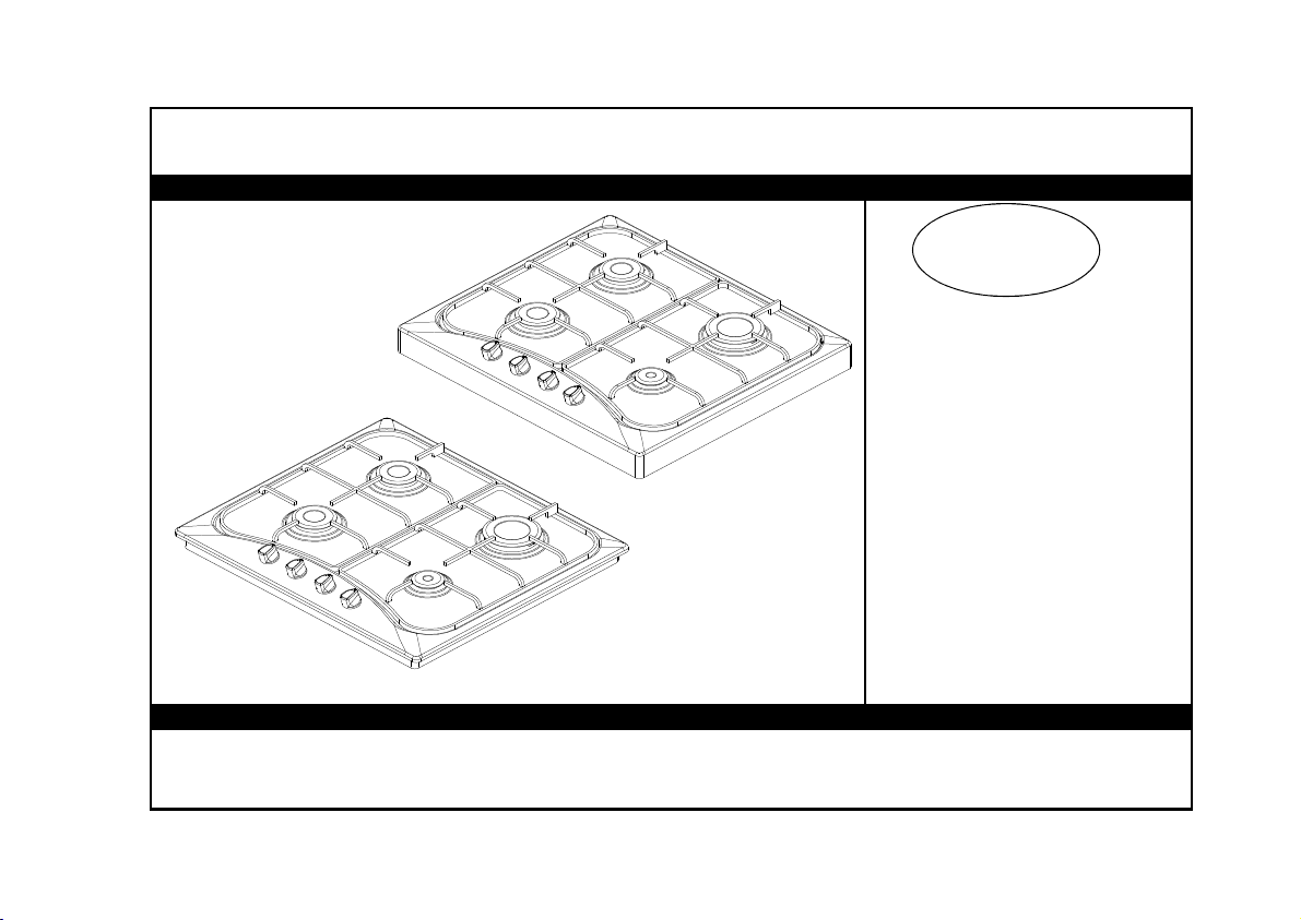
P0
MANUAL DE
INSTRUÇÕES
Page 3

ÍNDICE
Caro Cliente,
Desejamos que consiga atingir com os nossos produtos todas as suas tarefas,
este produto que passou a todos testes meticulosos
de controle de qualidade em instalações altamente modernizadas.
Por isso, recomendamos que leia todo o Manual de Instruções antes de utilizar o
seu aparelho pela primeira vez e guarde-o para futura referência.
1.
ÍNDICE
INSTALAÇÃO
2.
CARACTERÍSTICAS TÉCNICAS
3.
AVISOS IMPORTANTES
4.
DESCRIÇÃO DA PLACA E PAINEL DE COMANDOS
5.
MODO DE UTILIZAÇÃO
6.
MANUTENÇÃO E LIMPEZA
7.
1
Page 4
2
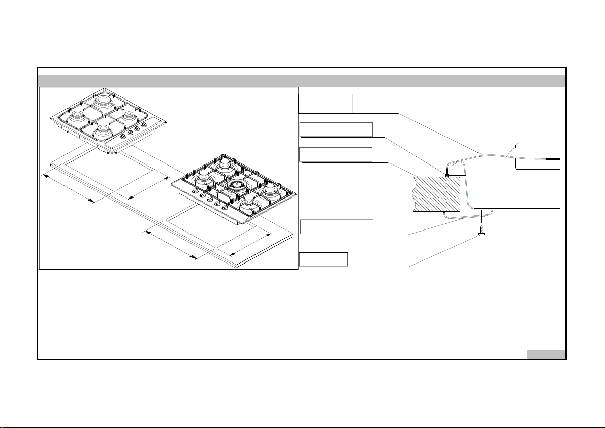
2 - INSTALAÇÃO DO APARELHO
PLACA SUPERIOR
TOP PLATE
JUNTA SILICONE
SILICON GASKET
MESA DE LIGAÇÃO
CONNECTION TABLE
5
6
0
m
m
Figure-1 Figura-2
m
m
5
9
4
GANCHOS LIGAÇÃO
5
6
0
m
m
m
m
5
9
4
CONNECTION CLIPS
PARAFUSO
SCREW
Page 5
0.65
0,97
Algumas das suas características aqui descritas não
Queimador Médio
Ajustamento da chama.
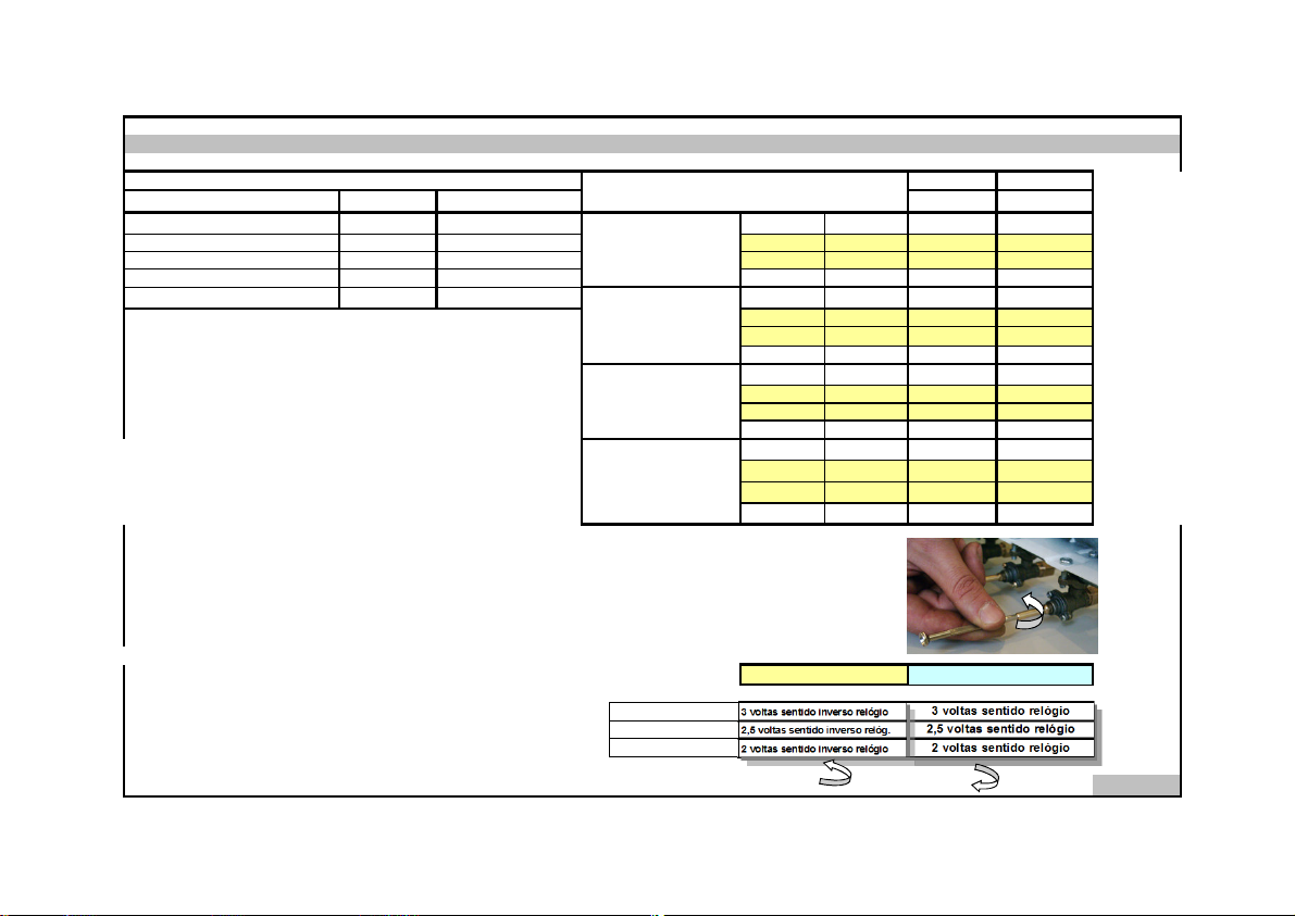
3 - CARACTERÍSTICAS TÉCNICAS
LARGURA EXTERIOR
LARGURA EXTERIOR
OR 640 SXI ORH 750
580 mm 680 mm Injectores mm
PROFUNDIDADE EXTERIOR 510 mm 510 mm
ALTURA EXTERIOR 85 mm 85 mm Potência KW
ESPECIFICAÇÕES
VALORES DOS INJECTORES DOS QUEIMADORES DE
ACORDO COM O TIPO DE GÁS
QUEIMADOR
Libertação Gás
m3/h
GRANDE
VOLTAGEM 230 V , 50 Hz 230 V , 50 Hz Chama KW
PLACA QUENTE 145 mmb (opt) 1000 W - Injectores mm
Para ajustar o seu aparelho para gás, proceda ao seu ajustamento, para reduzir a
chama vire cuidadosamente com uma pequena chave de fendas como mostra a
figura abaixo.
QUEIMADOR
MÉDIO
QUEIMADOR
PEQUENO
Libertação Gás
m3/h
Potência KW
Chama KW
Injectores mm
Libertação Gás
m3/h
Potência KW
Chama KW
Injectores mm
WOK QUEIMADOR
DO MEIO
Libertação Gás
Potência KW
m3/h
O que fazer antes de proceder à ligação do aparelho
Antes de usar o aparelho, leia com atenção este Manual de Instruções.
Neste Manual se encontram informações importante sobre a sua segurança,
como utilizá-lo e a sua manutenção.
Mantenha este Manual em bom estado de conservação, tendo em consideração de que
este aparelho poderá ser utilizado por outras pessoas.
LPG Gas Natural
G 30 G 20
0.85 1,15
0,082 0,289
2,600 2,600
0,700 0,715
0,046 0,143
1,500 1,500
0,500 0,385
0.50 0,72
0,028 0,080
0.900 0,900
0,320 0,300
0.96 1,30
0,028 0,080
3,6 3,600
Nota:
Este Manual foi elaborado para outros modelos.
estarão disponíveis no seu aparelho.
Queimador Grande
Queimador Pequeno
G30
G20,G25 G20,G25G30
De LPG para Gás Natural De Gás Natural para LPG
3 voltas sentido inverso relógio
2,5 voltas sentido inverso relóg.
2 voltas sentido inverso relógio
3 voltas sentido relógio
2,5 voltas sentido relógio
2 voltas sentido relógio
3
Page 6

4 - AVISOS IMPORTANTES
O seu aparelho enco ntra-se já equipado p ara Gás LPG. Se estive r preparado p/ Gás NG (Gá s Natural) existirá uma sigla "NG" na emba lagem.
1.
2.
Para as placas eléctricas a sua voltagem é de 230 Volt 50 Hz.
Se o valor actual do fusível na sua instalação é inferior a 16 Amp, fale com um electricista especializado para aumentar o fusível para 16
3.
Amp.
Já que a ficha d a sua placa vem equip ada comligação à terra, ce rtifique-se de que a tomada também se en contra equipada co m o mesmo sistema de ligação.
4.
Caso proceda à sua in stalação sem este sistema, o fabricante não se responsabiliza por perda s e danos que da í possam advir.
Mantenha as mangueiras do Gás e os cabos eléctricos longe de áreas quentes, não deixe que toquem no aparelho.
5.
Mantenha-os também longe de arestas afiadas ou áreas sobreaquecidas.
Caso verifique algum defeito nos cabos ou tubos contacte imediatamente um Técnico qualificado.
6.
Proceda à ligação do seu aparelho com uma válvula de 300 mmss (30 mbar) pressão exterior para gás LPG
7.
e 200 mmss (20 mbar) pressão exterior para Gás Natural (NG).
Proceda à ligação do seu aparelho ao Gás LPG num curto espaço e sem libertação de Gás.
8.
Quando proceder à verificação de fu ga de gás nunca use chama directamente, tais como, isqueiros, fósf oros, cigarros ou acessó rios similares.
9.
A utilização do seu aparelho poderá causar humidade e calor no local onde se encontra instalado, certifique-se de que a sua cozinha é
10.
bem ventilada. Mantenha os ventiladores bem limpos e sem qualquer tipo de obstruções.
11.
Aquando da sua utilização mantenha as crianças longe do alcance do aparelho.
Antes de ligar o seu aparelho, mantenha todos os objectos inflamáveis tais como, cortinas, tules, papéis, longe do mesmo.
12.
Não tenha produtos combustiveis ou inflamáveis em contacto directo com o aparelho.
Para desligar do quadro geral deverá proceder à separação da ligação em todos os polos que fornece o seu total corte, devendo
13.
incorporar a sua ligação de fios de acordo com as regras estabelecidas.
A ligação de Gás é feita por feixos de segurança. Não os ligar antes de pressionar o respectivo botão.
14.
Não utilizar o aparelho em locais de alta potência de atmosfera explosiva.
15.
Preste atenção aos minímos requisitos de saúde e segurança.
16.
4
Page 7
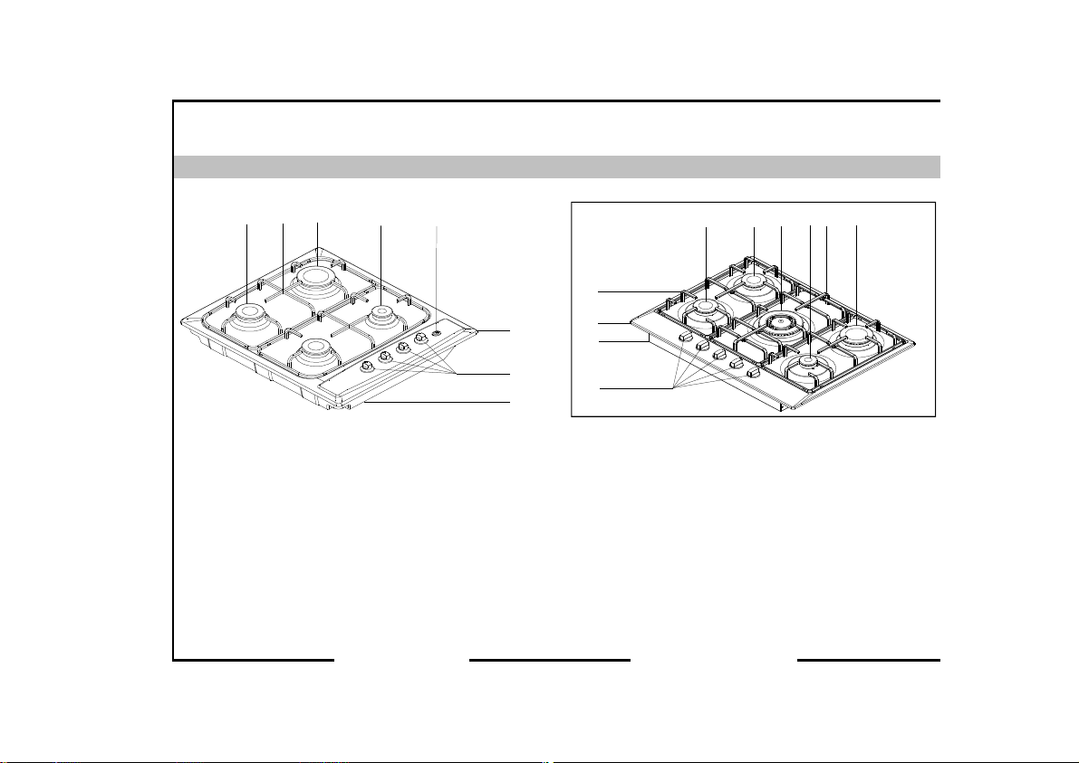
5 - DESCRIÇÃO DA PLACA E PAINEL DE COMANDOS
Model: OR 640 SXI Model: ORH750
1 2
3
4
5
6
5
6
789
10
4
3
2
7
1
8
1. Queimador Médio 1. Botões
2. Grelha 2. Parte inferior Mesa
3. Queimador Grande 3. Mesa trabalho
4. Queimador Pequeno 4. Grelha
5. Ignição Botões (Opt) 5. Queimador Médio
6. Mesa trabalho 6. Queimador Médio
7. Botões 7. Queimador Wok
8. Parte inferior Mesa 8. Queimador Pequeno
9. Grelha Wok
Queimador Grande
10.
Page 8
6 - MODO DE UTILIZAÇÃO
Utilização a Gás:
Para poder obter o máximo da sua função, certifique-se de que a panela que vai u tilizar a sua base seja lisa e plan a, e utilize-as
(dimensões) de acordo com a informação ab aixo indicada. As Válvulas que controlam o seu funcion amento vêm equipadas com um mecanismo de segurança.
Queim. Grande 24 - 28 cm 1. Pressione sempre o botão para o sentido do simbolo da chama virando-o no sent ido do relógio
Queim. Normal 18 - 22 cm (esquerda) Todos os acendedores deve rão funcionar, ligando somente o desejado.
Queim. Peq. 12 - 18 cm Mantenha o botão pressionado até que a ignição funcione (Opcion al).
2. Pressione o botão virando-o para a fren te e no sentido con trário do relógio (esquerdo)
Posição fechado,
significa extinsão de chama
* Nos modelos a Gás com sistema de segurança, quando a chama se encontra extinta, a válvula de segurança corta o Gás automáticamente (Opção).
Utilização Eléctrica:
Faça ajustamentos proced endo à rotação do botão no sentido do relógio de acordo com o nível de aquecimento que deseja utilizar.
Quando a luz por cima do b otão estiver acesa, isto sig nifica de que este se en contra ligado. Quand o acabar ponha o botão na posição.
Opções
145 mm
145 mm Rápido
** As placas eléctricas têm 3 n íveis de temperatura (acima indicada s). Mas, existem placas com 7 níveis (Opcional)
dependendo do modelo do seu apa relho poderá utilizá-lo desde o mínimo até ao máximo da sua potência.
Quando o utilizar pela 1 ª vez, ligue as placas na posição 3 por 5 minuto s, isto fará com que o agente das suas p lacas o qual é sensível
ao calor se manter endu recido ao queimar. Use sempre p anelas com a base lisa e plana para obter melho res resultados e mais rápidos,
poupando assim mais ene rgia.
Utilização a Gás :
NÍVEL 1 NÍVEL 1 NÍVEL 1 NÍVEL 1
95 W 1 55 W
135 W 1 65 W
temperatura normal
Os bicos a Gás superiores e inferiores funciona m em sistema de um de cada vez. Quando os qu iser ligar, deverá antes
pressionar o botão e e sperar aproximadamente en tre 5-10 segundos. P odendo a seguir ligá-lo com um fósforo. Deve rá esperar
aproximadamente entre 1 0-15 segundos dep ois da chama acesa, pa ra pressionar o botão e colocá-lo na posição de sejada.
Caso não consiga da primeira vez tente novamente . Aquando da u tilização da ignição, pod erá fechar após 3 -4 minutos.
Fechado Totalmente aberto Aberto p/ metade
250 W
250 W
NÍVEL 1 NÍVEL 1
400 W
500 W 1500 W
temperaturaAquecimento - baixa temperatura máxima
650 W
750 W
1000 W
6
Page 9

7 - MANUTENÇAÕ E LIMPEZA
1. Desligue a placa da electricidade ou feche a valvula do gás.
Aquando do funcionamento do aparelho ou logo a seguir ao mesmo a sua superfície se encontra muito quente.
2.
Deverá evitar de tocar nos bicos ou placas nessa altura.
3. Nunca kimpar a parte interior, painel, grelha, expalhadores e outras partes das placas com objectos tais como,
escovas grossas, produtos quimícos e corrosivos ou facas. Não utilizar produtos abrasivos ou detergentes.
4. Depois de proceder à limpeza da placa com um pano ensopado em sabão, passe água e limpe com um pano macio.
Não limpar a sua placa com aparelhos a vapor.
5.
6. Lave os expalhadores de vez em quando com água e sabão e limpe o interior dos queimadores com uma escova.
7. Não utilize produtos inflamáveis, tais como ácido, gasilina, etc, na limpeza da sua placa.
8. Não expalhar água na placa.
9. Limpe todas as peças removíveis com uma mistura de sabão. Não colocá-las na Máquina de Lavar Louça.
Page 10
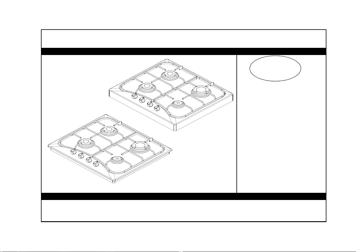
GAS COOKER
GB
ANKASTRE
USER MANUAL
Page 11

CONTENTS
Dear Costumer,
İt is our ultimate desire that you achieve the best performance from our product,
which has been passed through meticulous quality control
checks and is manufactured in modern facilities.
To this effect, we recommend that you read the entire guide carefully before operating
the product and keep it as a reference.
1.
INDEX
INSTALLATION OF YOUR COOKER
2.
TECHNICAL FEATURES OF YOUR COOKER
3.
IMPORTANT WARNINGS
4.
DESCRIPTION OF COOKER & CONTROL PANELS
5.
USING COOKER SECTION
6.
MAINTENANCE and CLEANING
7.
9.
GAS CATEGORY LIST
10.
GAS SCHEME
1
Page 12
2 - INSTALLATION OF YOUR COOKER
ELECTRICAL CONNECTION and SECURITY
Your cooker requires a 16 Amp fuse. If necessary, installation by a qualified electrician is recommended.
1.
Your cooker is adjusted in compliance with 230 Vac 50 HZ electric supply. If the mains is different from this specified value, contact your authorized
2.
service.
3.
Electrical connection of the cooker should only be made by the sockets with earth system installed in compliance with the regulations. If there is no
proper socket with earth system in the place where the cooker will be placed, immediately contact a qualified electrician. Manufacturer shall never be
responsible from the damages that will arise because of the sockets connected to the appliance with no earth system. If the ends of the electrical
connection cable is open, according to the appliance type, make a proper switch installed in the mains by which all ends can be disconnected in case
of connecting / disconnecting from / to the mains.
If your electric supply cable gets defective, it should definitely be replaced by the authorized service or qualified electricians in
4.
order to avoid from the dangers.
Electrical cable shouldn't touch the hot parts of the appliance.
5.
GAS CONNECTION and SECURITY
Fit the clamp to the hose. Push one of the hose until it goes to the end of the pipe
1.
by heating in boiling water, and tighten the clamp with screw driver.
For the sealing control; ensure that the buttons in the control panel are closed,
2.
but the gas cylinder is open. Apply some soap bubbles to the connection.
If there is gas leakage, there wil be foaming in the soaped area.
RE-INSPECT THE GAS CONNECTION.
DO NOT MAKE GAS HOSE and ELECTRICAL CABLE OF YOUR COOKER GO THROUGH THE HEATED AREAS,
SPECIALLY THROUGH THE REAR SIDE OF THE COOKER. DO NOT MOVE GAS CONNECTED COOKER. SINCE THE
FORCING SHALL LOOSEN THE HOSE, GAS LEAKAGE MAY OCCUR.
2
Page 13
3
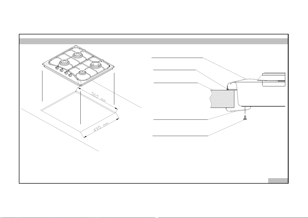
2 - INSTALLATION OF YOUR COOKER
Figure-1 Figure-2
TOP PLATE
SILICON GASKET
CONNECTION TABLE
CONNECTION CLIPS
SCREW
Page 14
0.65
0,92
0.92
Med. Burner
3 - TECHNICAL FEATURES OF YOUR COOKER
OUTER WIDTH
2,5 turns clockwise
2,5 turns anticlockwi
OUTER DEPTH Injector mm
OUTER HEIGHT Gas Flow m3/h
SUPPLY VOLTAGE Power KW
HOT PLATE 145 mm
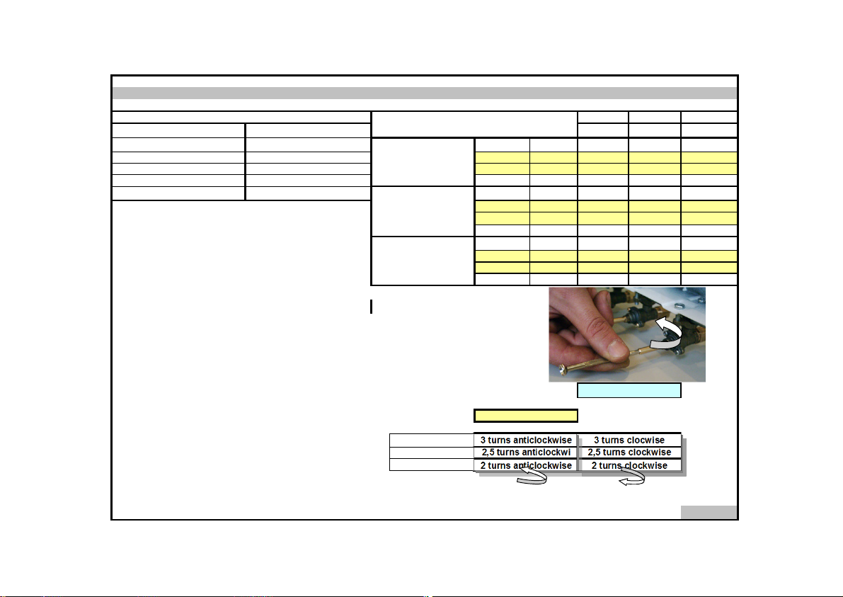
To adjust your oven acc. to the gas type, make the adjust. for reduced
flame carefully by turning with a small scredriver as shown below on the
scr.in the mid. of the gas cocks as well as nozzle changes.
SPECIFICATIONS
580 mm
510 mm
85 mm
230 V , 50 Hz
900 W
BURNER INJECTOR VALUES
ACCORDING TO THE GAS TYPE
Big Burner
Red'd flam KW
Injector mm
Medium Burner
Small Burner
Gas Flow m3/h
Power KW
Red'd flam KW
Injector mm
Gas Flow m3/h
Power KW
Red'd flam KW
Before making the connections of the appliance
Before starting to use the appliance, read the user manual of the
appliance carefully. In this user Manual, there are important information
regarding your, our customers security, how you will use it and how you
will make its maintenance.
Keep this user manual in good shape, by taking into consideration that
the appliance shall be used by others.
Note :
Some of the features specified in the Manual may not be
available in your appliance.
Red'd Flame Gas Cock Adjustment:
This user manual is prepared for more than one model.
Big Burner
G30
G20,G25
From LPG to Nat.gas from Nat.gas to LPG
3 turns anticlockwise 3 turns clocwise
LPG Natural Gas Natural Gas
G 30 G 20 G 25
0.85 1,35 1,35
0,082 0,289 0,315
2,600 2,700 2,540
0,700 0,715 0,69
0,046 0,143 0,166
1,500 1,330 1,350
0,500 0,385 0,360
0.50 0,70 0,70
0,028 0,080 0,088
0.900 0,760 0,715
0,320 0,300 0,300
G20,G25
G30
Small Burner
2 turns anticlockwise
2 turns clockwise
4
Page 15

4 - IMPORTANT WARNINGS
1.
Your cooker is adjusted for LPG (cylinder) gas. If it is adjusted for NG (Natural Gas) there is an "NG" sign on the package.
2.
Power supply voltage of your cooker is 230 Volt 50 Hz.
If the current rate of the fuse in your installation is less than 16 Amp, make a qualified electrician fit a 16 Amp fuse.
3.
4.
Since the plug of your cooker has earthing system, ensure using socket with erarth system. If it is used without earth system,
our firm is not responsible for any loss which may arise
5.
Keep the gas hose and electrical cable of your oven away from the hot areas, do not let them touch the appliance.
Keep them away from sharp sides and heated surfaces.
6.
When the supply cable gets defective, get it replaced by conducting our service as soon as possible.
Connect your appliance with a valve with 300 mmSS (30 mbar) output pressure for LPG gas and with 200 mmSS (20 Mbar)
7.
output pressure for Natural Gas (NG).
8.
Connect your cooker to LPG cock in shortest way and without any leakage.
9.
When making gas leakage check, never use any flame type like those of lighter, matches, cigarette fire or similar ones.
10.
Usage of your appliance creates moisture and heath in the room it is placed, make sure that your kitchen is ventilated well.
Maintain the natural ventilation ducts properly.
11.
When the cooker is being used, the reachable parts may be hot, children should be kept off them.
12.
Before starting to use your appliance, keep curtain, tulle, paper or inflammable things away from your appliance.
Do not keep combustible or inflammable things in or on the appliance.
13.
For disconnection from the supply mains having a contact seperation in all poles that provide full disconnection,
must be incorporated in fixed wiring in accordance with the wiring rules.
14.
Gas tapes are secured by locks. Do not turn before pressing the button.
15.
Do not use cooker in potentially explosive atmospheres.
16.
Pay attention to minimum health and safety requirement.
5
Page 16
5 - DESCRIPTION OF THE COOKER AND CONTROL PANEL
7
1
2
3
6
5
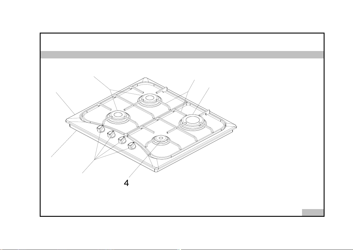
Cooker body
1.
Bottom body
2.
Knobs
3.
Small burner
4.
Big burner
5.
Grid
6.
Middle burner
7.
6
Page 17
6 - USING COOKER SECTION
Using Gas Burners :
In order to obtain maximum outp ut, be careful that t he saucepan which will be used should b e flat bottomed, an d use the saucepa ns
with dimensions given he rein belove. The valves co ntrolling the gas cookers h ave special security mechanism. In order to light the coo ker;
Large Cooker 24 - 28 cm 1. Always press on the switch forward and bring it to flame symbol by turning an ticlockwise (left).
Normal Cooker 18 - 22 cm All of the lighters shall operate an d the cooker you con trolled shall light only. Keep the switch pressed u ntil
Aux. Cooker 12 - 18 cm ignition is performed . (OPTION)
2. Press on the lighter button by pressing o n the switch forwa rd and turning anticlockw ise (left).
It means Closed Position.
Flame is extinguished
* In models with Gas Security System, when flame of the cooker is extinguished, control valve cuts off the gas automatically. (OPTION)
Using Electric Hotplates :
Make adjustment by rotating the switch clockwise a ccording to the heat level you wish to use for your electric cooker. When the
warning lamp lights over th e switch, this means tha t the cooker is engag ed. When the co oking is over bring it back to position.
145 mm
145 mm Rapid 500 W
** Electric Hotplates have sta ndard of 3 tempe rature levels (as described he rein above) . But, the re are hotplate models with 7 levels (optional)
depending on you r cooker model that you can use from minimum to maximum temp erature.
When u sing first time, operate yo ur electric hotplate in po sition 3 for 5 minutes. This will make the agent on your hotplate which is sen sitive
to heat get harde ned by burning. Use f lat bottomed sauce pans which fully conta ct with the heat as much as you can, so that you can use
the energy more product ively.
Using Burners :
LEVEL 1
250 W
Heating - at low cooking Frying
temperature temperat ure
The our gas ovens top and bottom burner wo rking system is one by one. When you wa nt use your prefere nce burner, before you must make
press the tap knob a nd wait nearly 5-10 secon d. Then you can to inflame trought with matc h. You must wait 10-15 secon d after the inf lame
to have press by tap knob and after yo u can make allow the kno b. İf you can not made this operation you must try again.
When you ma ke the ignition operatio n, then you can clo se the oven door 3 -4 minute after.
Closed Fully Open Half Open
LEVEL 2 LEVEL 3
650 W
1000 W 1500 W Option
at normal cooking
900 W
7
Page 18

Never clean the interior part, panel, grids, burner cover and all other parts of the cooker by the tools like hard brush, cle
While cooker is operating or shortly after it starts operating, it is exteremely hot. You must avoid touching heating elem
7 - MAINTENANCE and CLEANING
1. Disconnect the plug supplying electricity for the cooker from the socket and cutoff the gas by closing the gas valve.
2.
3.
mesh or knife. Do not use abrasive, scratching agents and detergents.
4. After cleaning the interior parts of the cooker with a soapy cloth, rinse it and then dry thoroughly with a soft cloth.
Do not clean your cooker with steame cleaners.
5.
6. Wash the heads of the burners sometimes with soapy water and clean the gas ducts by means of a brush.
7. Never use inflammable agents like acid, thinner and gasoline when cleaning your oven.
8. Do not splash water onto the cooker.
9. Clean removable burner parts with a hot soap solution.Do not clean in the dishwasher.
Page 19
8 - GAS CATEGORY LIST
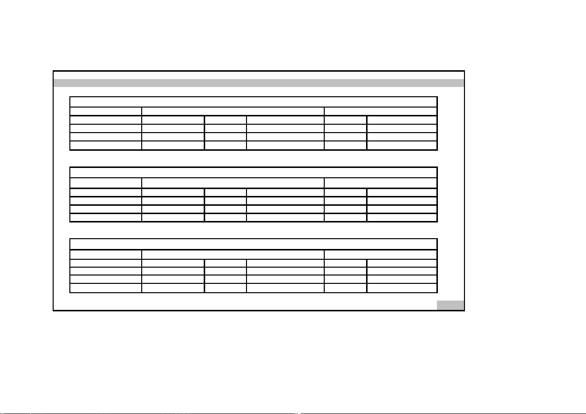
BURBER TYPE MINIMUM BURNING FULL BURNING
SMALL 0,50mm
MEDIUM 0,65mm
BIG 0,85mm
İnjection Diameter
KW(NET)
0,,320
0,5
0,7
Gas consumpion.m3/h KW (NET) Gas consumpion.m3/h
0,01 0,9
0,,017 1,5
0,021 2,6
0,028
0,046
0,082
GAS CATEGORY G25
GAS CATEGORY G30
BURNER TYPE MINIMUM BURNING FULL BURNING
SMALL 0,70mm 0,037
MEDIUM 0,92mm
BIG 1,35mm 0,085 2,54
İnjection Diameter
KW(NET)
0.300
0,36
0,69
Gas consumpion.m3/h KW (NET) Gas consumpion.m3/h
0,715
0,045 1,35
0,088
0,166
0,315
BURNER TYPE MINIMUM BURNING FULL BURNING
İnjection Diameter
SMALL 0,70mm 0,033
MEDIUM 0,92mm 0,04 1,33
BIG 1,35mm 0,076 2,7
KW(NET)
0.300
0,385
0,715
Gas consumpion.m3/h KW (NET) Gas consumpion.m3/h
0,76
0,143
0,289
GAS CATEGORY G20
0,08
9
Page 20
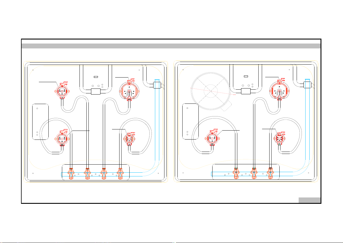
10
9 - GAS SCHEME
G30= 0.65mm
G20= 0.92mm
G25= 0.92mm
G30= 0.85mm
G20= 1.35mm
G25= 1.35mm
900 W
G30= 0.85mm
G20= 1.35mm
G25= 1.35mm
145
G30= 0.65mm
G20= 0.92mm
G25= 0.92mm
G30= 0.50mm
G20= 0.70mm
G25= 0.70mm
G30= 0.65mm
G20= 0.92mm
G25= 0.92mm
G30= 0.50mm
G20= 0.70mm
G25= 0.70mm
 Loading...