

Origin Live Sovereign MKI User Manual
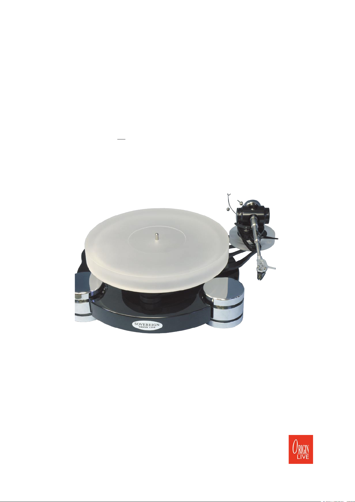
S O V E R E I G N T U R N T A B L E
O W N E R M A N U A L
Avoid scratching the high grade finish. To clean the surface use a soft lint free cloth such
as a duster – do not use tissue paper or kitchen towel as these are mildly abrasive – the
surface.
1

Introduction (read carefully)
Congratulations on choosing your Origin Live Sovereign turntable. You now have one of the finest sounding turntables available
– not only will it provide an extraordinary level of performance but also reliability and low maintenance.
It is critical that these instructions are read fully to achieve the full performance from your turntable. There are aspects of the
deck that run contrary to what you may expect, so before altering anything it is important to have fully read the manual or
degradation will result.
The Sovereign turntable is simple to set up. If you have a problem please refer to the instructions. If your problem persists you
should speak to your dealer or have a look at the Origin Live web site www.originlive.com under “general information” then
“technical support” from the drop down list
The instructions are written for people with no previous experience of turntables. Some sections may therefore appear lengthy,
as they need to cater for all potential questions. When reading the instructions refer to the various diagrams for part names and
clarity.
The deck can take approximately 15 minutes to set up depending on your expertise. The dc regulator electronics may initially
encounter speed drift when first started (if they have not been run in) and may need at least 4 hours to run in before the speed
can finally be set with accuracy.
We wish you an enjoyable time with your Sovereign turntable.
Parts list
When you unpack the deck, check that you have all the items listed in the parts list.
Plinth
Turntable bag
o Belt
o 1 cable clip and attachment screw (may be on deck)
o Bottle of Oil
o 3mm Allen key
o 2.5 mm Allen key
o 30mm Spacer tube
Platter
Sub-platter
Sub-chassis
Motor pod, DC200
Ultra Control box
Upgrade Transformer for 230 volt or 110 volt mains supply
Arm (optional)
P A P E R W O R K
Turntable instructions
Strobe card
2

S E T T I N G U P T H E P L I N T H
L E V E L T H E T U R N T A B L E P L I N T H
The deck has screw feet in the underside of each large chrome pod. These can be used
to adjust the height of the pods. They rotate easily and can be adjusted by lifting a pod
by hand, to approx 25mm height and rotating the foot with your fingers. If the screw
is tightly screwed in, then it can be loosened using the allen key provided. You need not
lock these feet once you have adjusted them.
Place the motor pod in position and then lower the
plinth over it as shown in photo.
Ideally use a round spirit bubble level to level the plinth.
There ar 2 methods to level the deck depending on whether you have a support table
that can be levelled.
1) Screw in each threaded foot such that it protrudes from the base of the pod by approx
1mm. Then level the table that the deck sits on till the plinth is level.
2) Alternatively - level the deck using the threaded feet.
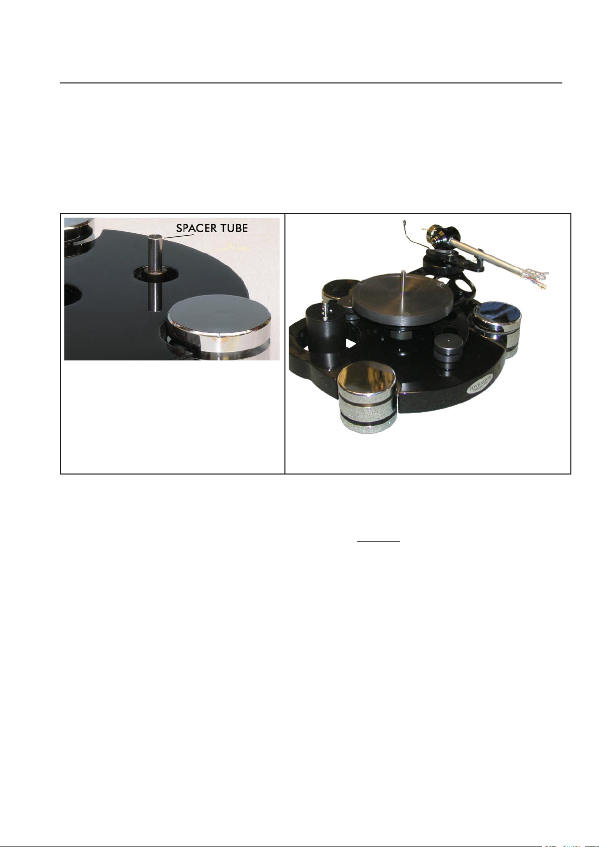
You will find the spacer support post fitted as shown
in the diagram minus the spacer. Fit the 30mm spacer
tube over the support post as shown opposite.
NOTE: The 3 bolts underneath the plinth holding it
to the bottom silver plate should only be finger tight
– do not tighten these as the sound will degrade if
you do.
3
S E T T I N G U P T H E S U B - C H A S S I S
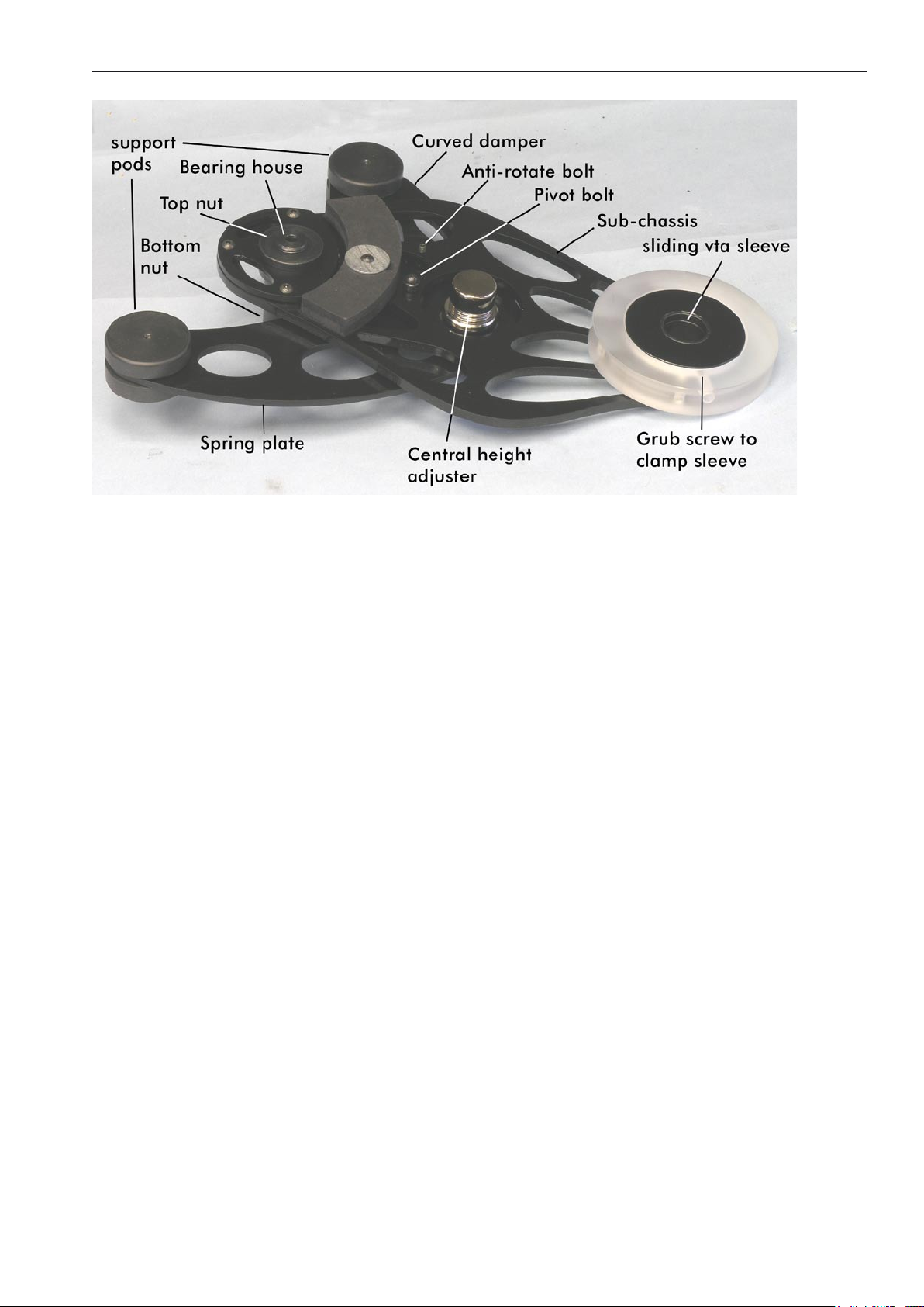
NOTES:
Before fitting the sub-chassis examine the central height adjuster to get an idea of how it works and the extent of its adjustment.
DO NOT TIGHTEN ANY BOLT SETTINGS ON THE SUB-CHASSIS OR IT WILL DEGRADE THE PERFORMANCE, this
applies to the pods which are deliberrately loose. The curved damper is part of the sub-chassis and should not be removed.
The sub-chassis is attached to the “spring plate” by one “pivot bolt” – the two plates should be free to swivel slightly and are loosely restrained
by an “anti-rotate bolt”
If the setting on the pivot bolt is lost for any reason then the correct tension is such that the spring plate can rotate freely in relation to the
subchassis plate but has minimal “rocking” motion.
4
F I T T H E S U B - C H A S S I S T O T H E P L I N T H
Place the sub chassis on the plinth over the spacer tube as shown in the photo below. Make sure that the small plastic locating pins on
the underside of the two black plastic pods locate in the small holes on the plinth. DO NOT TIGHTEN THE BOLTS IN THE PLASTIC
PODS - they are set to be very loose deliberately - if they are tightened sound degradation will result.
When placing the sub-chassis on the plinth, the spacer tube must be located centrally in the central height adjuster. If the spacer is not
located properly it will not be possible to level the turntable correctly.
You will find that the sub-chassis can move very slightly on the plinth – push it gently so that the bearing moves towards the motor pod.
Before fitting sub-chassis ensure spacer tube is fitted as
shown
Photo showing subchassis fitted along with motor pod and tonearm.
F I T T H E S U B - PL A T T E R & P L AT T E R
With the Bottle supplied, run approx 5 drops of oil into the top of the bearing house.
Wipe the sub-platter spindle surface to ensure that it is absolutely clean and very gently insert the sub-platter into the bearing
house (If the oil does not overflow when the spindle touches the bottom then try 2 drops at a time till you just achieve overflow
- wipe away excess oil) and then place the platter on top.
NOTE:
The bearing needs a few minutes to “run in” and should run silent when truly vertical and full of oil - if it doesn’t do so, there
has probably been contamination with dust and you will need to clean it out with a lint free paper towel or similar wrapped
around a thin rod. If you do this, be sure to also wipe the oil off the spindle as this also may contain microscopic contamination
that is not visible.
F I T T H E B E L T
Locate the motor pod approx in the centre of the circular cut out in the plinth. – It is important that the motor pod does not touch
the sub-chassis or plinth for the sake of sound quality.
Fit the belt over the motor pulley and sub-platter.
Set the belt tension by positioning the motor housing relative to the turntable. Ideally the centre of the pulley should be approximately 122
- 124mm from the centre of the bearing house.(fig 6).
5
NOTE:
It is possible for people to set the belt tension too tight, which degrades performance. The optimum setting is where there is
enough tension to turn the platter without audible wow and flutter but no more. This makes take some experimentation.
It also aids performance to clean all the running surfaces with mentholated or surgical spirit.
Fit the platter.
F I T T H E T O N E A R M
Heavier tonearms
NOTE: with heavytonearms the sub-chassis may become unstable with the platter off – it can tip up and possibly damage the finish so be
carefull to hold it when removing the platter etc.
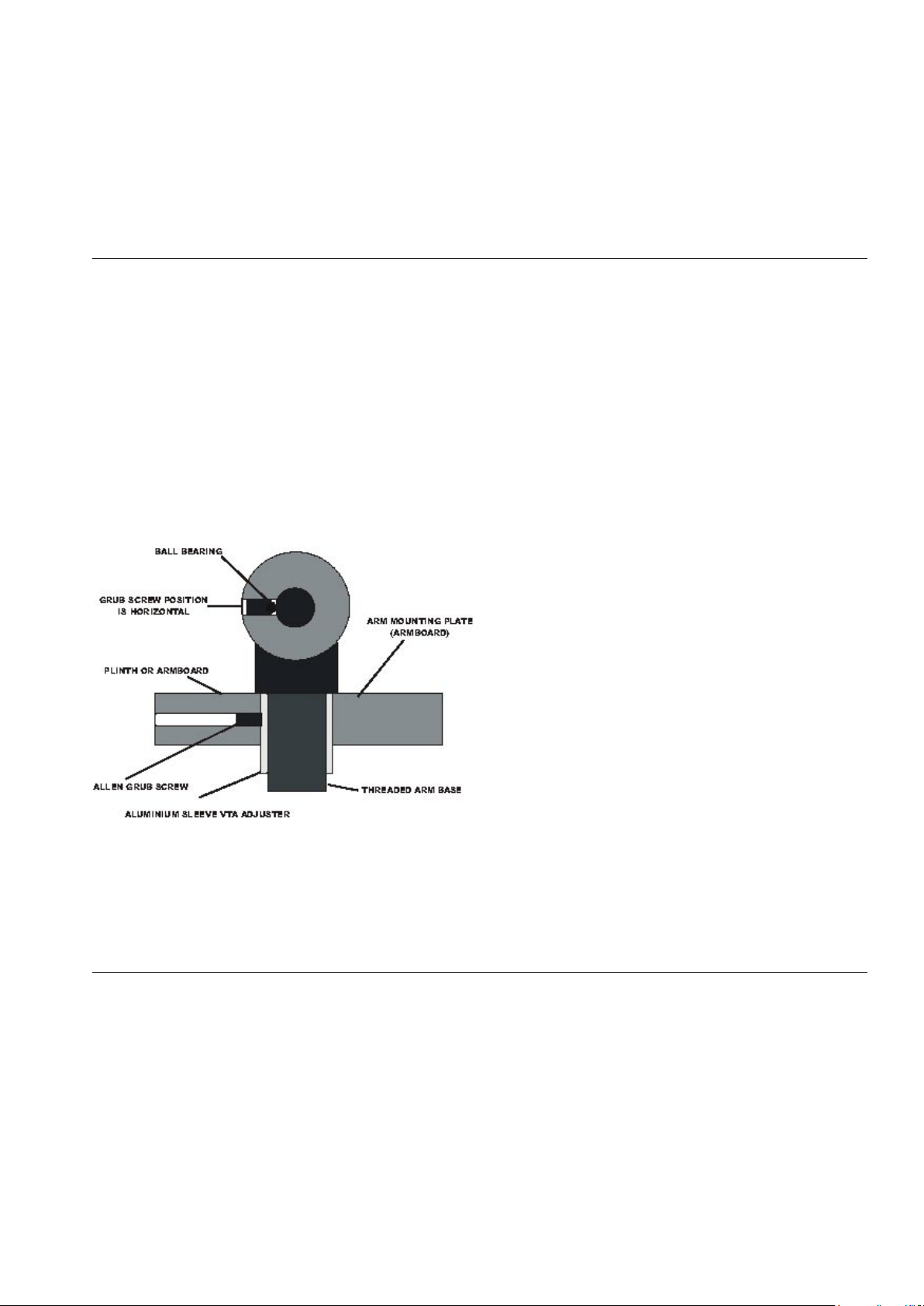
Fitting
Insert your tonearm into the metal VTA sleeve located in the arm board. You can set the arm to the correct height using the setscrew located
in the arm board as shown in the photo below. This set screw clamps the VTA sleeve onto the arm board. Further to this, when clamped, it
deforms the metal sleeve sufficiently onto the arm base to allow it to clamp the arm in position.
Diagram showing the fitting of the arm to the armboard and VTA sleeve.
It doesn’t matter whether you slide the VTA sleeve up and down in the arm board to get the height right or slide the arm base in the VTA
sleeve. Both methods work fine. Note that you should NOT clamp the VTA sleeve hard when there is no arm fitted inside. If you do this,
then permanent deformation will result – the slightest of “nips” is all that is necessary. You not need to fit the large arm base nut, the serrated
washer or the knurled threaded vta adjuster supplied with some of our arms.
L E V E L L I N G T H E S U B - C H A S S I S & D E C K
Try an initial approximate levelling of the subchassis by rotating the central height adjuster. Rotating the height adjuster clockwise raises the
arm board end of the sub-chassis and vica versa. The plastic posts should be ignored because they are a fixed height. You should always take
level from the platter – A bubble level is particularly useful for this task.
Final levelling of the Sovereign can be carried out using the adjustable cork feet in the underside of the pods.
C O N N E C T T H E M O T O R D R I V E .
6
 Loading...