

Page 1

Page 1
Mk2 Turntable Manual
for Aurora, Calypso, Resolution & Sovereign
*** NOTE : Speed must be reset accurately after 3 days of continuous running at
33rpm ***
It cannot be overstated that it is VERY important to read these instructions to
really get the best out of your deck and avoid making incorrect assuptions some things about the deck are counter intuitive.
Page 2
Page 2
I N T R O D U C T I O N
Read Carefully - Congratulations and thankyour for
choosing an Origin Live turntable. You now have one of the
finest sounding turntables available – not only will it provide
an extraordinary level of performance but also reliability and
low maintenance. These instructions cover all decks listed on
the front cover, so photos and diagrams are for illustration
only. Specific instructions for a particular deck are always
included.
Critical performance factors should be noted as follows:
Adjustable feet to be clear of plinth
Belt tension as it affects speed
Arm fastening tightness (read carefully as it depends on the
arm)
The portions of the instructions printed in grey are optional
reading that provide additional information if required. It is
critical that the remainder of the instructions are read fully
to achieve full potential performance. Underlined text is
especially important.
Although the instructions are written for owners with no
previous experience of turntables, there are aspects of the deck
that run contrary to expections, so experts should note that
before altering anything it is important to have fully read the
“non greyed” instructions or degradation will result.
An Origin Live turntable is simple to set up. If you have a
problem, please refer to the instructions - failing this, you
should speak to your dealer or refer to technical support
on the Origin Live web site www.originlive.com - See top
navigation bar “dealers & information” then “technical
support” from the drop down list.
The deck can take approximately 20 minutes to set up
depending on your expertise. It can then be played and
later on the speed can finally be set with absolute accuracy.
As explained later this is because the electronics initially
experience speed drift (if they have not been run in) and may
need at least a day to run in properly.
We wish you an enjoyable time with your Origin Live
turntable.
P A R T S L I S T
Check that all parts are present.
Plinth & Sub-chassis - including 1 cable clip
with nut & bolt.
Turntable bags
o Threaded VTA adjuster (not for
Resolution or Sovereign )
o Cork washer for arm
o 4mm thick spacer for 3 point mounting
on Aurora & Calypso only
o Oil bottle
o screwdriver
o 2.5mm & 3mm allen key for arm clip
o 2 plastic + 1 steel foot (Sovereign only)
Platter (+ upgrade plattter mat for Resolution
& Sovereign only)
(Sovereign only) Sub-platter
1 Belt
Motor pod
Standard or upgrade transformer for 230 volt
or 110 volt mains supply
Arm (optional)
Turntable instructions & Strobe card
A V O I D S C R A T C H I N G T H E
H I G H G R A D E F I N I S H
To clean the surface use a soft lint free cloth
such as a duster – do not use tissue paper or
kitchen towel as these are mildly abrasive.
P R E P A R A T O R Y N O T E S
Your pre-assembled deck is illustrated in the adjacent
diagram. It is not necessary or advisable to dismantle the
deck.
You might make the mistake of thinking that the subchassis is loose but in fact it is designed with freedom to
rotate very slightly from side to side but not “rock” up and
down much.
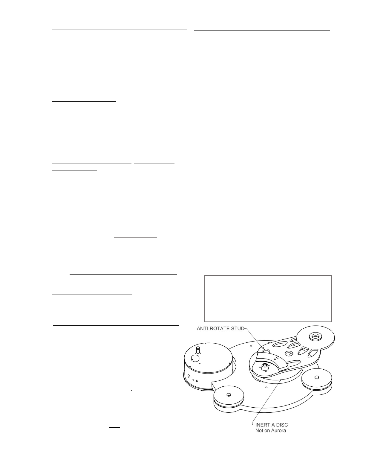
AURORA & SOVEREIGN ONLY - Note the anti-rotate
stud is replaced by a bolt which is factory fitted to the subchassis. This should not be tampered with – it does not
bolt to the plinth as it’s only function is to stop the subchassis rotating.
ALL OTHER DECKS - Note “the anti-rotate studs”
protrude either side of the inertia disc and locate in the
sub-chassis and plinth to prevent rotation.
DECK PRIOR TO INSERTING PLATTER
Page 3
Page 3
Sovereign deck only - Thread on the 2 plastic feet into the 2
front pods and the steel foot into the rear pod.
F I T T H E T O N E A R M
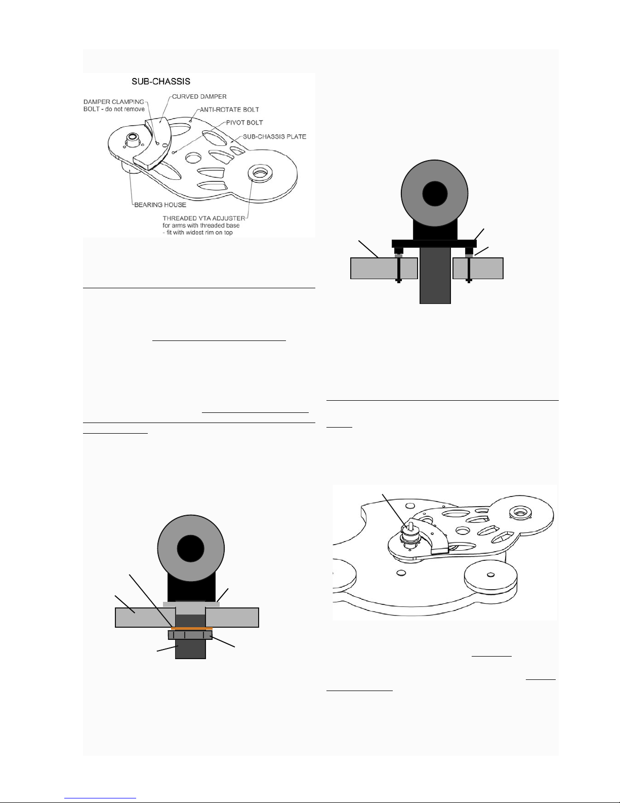
Mounting Origin Live arms
Thread the threaded vta adjuster onto your arm if it is an Origin Live
Encounter or above. If your deck is a Resolution or Sovereign and
you have an Encounter arm or above - do not fit the threaded vta
adjuster. The adjuster must be oriented such that the largest diameter
is uppermost. Insert your tonearm into the armboard hole such that
the vta adjuster locates centrally. Next fit the cork washer as shown in
the diagram below before threading on the large clamping nut. You
can set the arm to the correct height later but for now just clamp the
arm in position using the large nut. To adjust the height of the arm,
screw the vta adjuster up or down and reclamp the arm using the large
base clamping nut.
NOTE - For Origin Live arms with integral vta adjuster i.e Encounter
and above you should raise the arm height to just below the right level
using the threaded vta adjuster and then use the arm vta wheel for
fine adjustment.
A R M
REAR VIEW OF ARM ON ORIGIN LIVE DECK WITH
THREADED VTA AND CORK WASHER
ARM MOUNT
SURFACE
CORK WASHER
LARGE CLAMPING NUT
THREADED ARM BASE
THREADED
VTA ADJUSTER
If you have the OL1 or Rega arm with 3 hole
mounting
The arm is bolted or screwed to the deck using the 3 mounting holes
in the base of the arm. To raise the arm for VTA adjustment you will
need to fit 3 or more spacing washers under the arm base holes. One
peice spacers are available from Rega if you want a neater looking
solution.
3 POINT ARM MOUNTING
Sub-chassis or
armboard
3 off bolts or
wood screws
Spacers
For other makes of tonearm
Origin Live can provide the correct cut out in the sub-chassis or
armboard for other makes of arm and after this refer to your arm
installation instructions.
F I T T H E P L A T T E R
NOTE - On newer decks (April 2009 onwards) the platter is a
“loose” fit over a metal bush on the spindle. This means the platter
can be removed from the spindle.
Oil the bearing - with the small oil bottle supplied, run approx 10
drops of oil into the top of the bearing house.
SPINDLE FOR PLATTER
(OR SOVEREIGN SUB-PLATTER)
Insert the spindle - Wipe the platter spindle surface first
to ensure that it is absolutely clean and very gently insert it
into the bearing house (If the oil does not overflow when the
spindle touches the bottom then try 2 drops at a time till you
achieve overflow - wipe away excess oil without withdrawing
the spindle. Ideally you should spin the spindle slowly as it
settles into the bearing to ensure distribution of oil.
When you oil the bearing you can get a false impression of
overflow if the spindle has oil on it - the oil simply scrapes off
as the bearing goes in and ends up on the top of the bearing
Page 4

Page 4
house. You can “feel” overflow when inserting the spindle, it
meets resistance at the bottom which is not a “thud” of the
spindle hitting the bottom but rather a build up of pressure of
the bearing landing on a bed of oil. By further pressing, you can
then see the oil being squeezed out at the top.
Carefully lower the platter over the spindle till it rests on the
lower flange of the platter bush (ensure mating surfaces are
clean). Once the platter is fitted over the bush it pays to spin it
slowly by hand while holding the top of the spindle stationary
with your other hand - this helps the platter to “bed down”
onto the bush and become more level.
SOVEREIGN DECK ONLY: NOTE - On newer decks
(April 2009 onwards) the sub-platter is a “loose” fit over the
spindle and can detatch from the sub-platter.
Wipe the sub-platter spindle surface first to ensure that it
is absolutely clean and very gently insert it into the bearing
house (If the oil does not overflow when the spindle touches
the bottom then try 2 drops at a time till you just achieve
overflow - wipe away excess oil without withdrawing the subplatter. Next place the sub-platter on the spindle such that the
less recessed side is uppermost.
UNDERSIDE OF
SUB-PLATTER
TOPSIDE OF
SUB-PLATTER
Lastly, place the platter on top of the sub-platter and follow this
with the thin black platter mat .
If you have the heavyweight platter then raise the plinth more
than normal by winding out the adjustable feet, till the platter
no longer fouls on the motor pod. The belt must NOT run in
the groove of the platter. Do not tighten up the allen bolts in
the underside of the platter - these sound best with minimum
tension.
NOTES:
The bearing fit is carefully toleranced to run fully loaded
with the specific oil we supply. It needs at least 10 minutes to
distribute the oil evenly over the running surfaces and approx
24 hours to properly “run in”. It needs this because of the exact
tolerances (0.0001”)which “float” the bearing off the side walls
to avoid metal to metal contact and also minimize viscous drag.
Eventually it should run virtually silent when truly vertical
and full of oil - if it doesn’t do so, there has probably been
contamination with dust and you will need to clean it out with
a lint free paper towel or similar wrapped around a thin rod. If
you do this, be sure to also wipe the oil off the spindle as this
also may contain microscopic contamination that is not visible.
Do not use any other oil than Origin Live oil.
Do not tamper with the bolt in the bottom of the bearing
or oil leaks will occur and you will probably not succeed in
re-tightening it.
The thrust plate at the bottom of the bearing house may
appear to be discoloured or dirty - you should not attempt
to clean this up as it is part of the hardening process - the
centre of the plate is polished as this is the only part that
the spindle touches.
The Platter works best with the Origin Live platter mats but these are
not necessarily included in the lower part of the deck range - all of the
many other mats we have tried do not work on the OL decks.
L E V E L T H E D E C K
The 3 feet under the plinth are all threaded so that by rotating
them you can adjust the level of the deck - Rotate all three feet
so that the top of the foot does not touch the plinth and only
sits on the thread alone - this is for best performance. At this
stage check that the bearing house is at least 1mm clear
of touching the surface your deck is standing on (Aurora
only).
Note that when you level the deck, the only thing that matters
is that the platter (not the plinth) is level. Sometimes there
may be a slight discrepancy between the level of the plinth and
platter but this does not matter and is usually imperceptible
visually.
P O S I T I O N M O T O R P O D & F I T
B E L T
Position the motor pod roughly as shown in previous diagrams.
The pod should be oriented as shown, such that the switch is at
the front. Ideally the centre of the pulley should be somewhere
between 215mm (8.45inches) to 225mm (8.9 inches) from
the centre of the platter. We recommend and set up the speed
at factory at 217mm. The pod must not touch the plinth so
rotate it if necessary. Fit the belt over the platter first and then
pull it over the motor pulley taking care not to twist it.
Page 5

Page 5
If you don’t have a ruler handy, another method of setting
the belt tension is to install the belt first. Do this by placing it
round the platter and then pull it onto the pulley, taking care
that there is no twist in the belt.
Now, lift the belt off the pulley and let it lose it’s tension
almost completely whilst still holding it gently - With no
tension whatsoever in the belt, you should stretch it approx
25mm to fit over the pulley. If this is not the case, move the
pod to achieve correct pulley position.
Alternative method of belt fitting (greyed text).
Refer to photos showing belt being fitted - Fit the belt over
the motor pulley and outer rim of platter. This is most
easily carried out by placing the belt over the pulley and then
holding it there loosely with one finger of your left hand.
Whilst retaining the belt on the pulley, hold the belt onto the
rear rim of the platter with the index finger of your right hand.
Now rotate the platter slowly clockwise with your right hand
index, all the time pressing the belt on the rim, till the belt is
completely on. Allow the motor pulley to rotate under your
finger whilst retaining the belt on the pulley and maintaining
slight tension on the belt between the pulley and rear of
platter.
The belt has an ideal tension for best performance - too
tight and motor bearing friction increases causing possible
speed instability and increased wear plus a decrease in sonic
performance. The correct distance is not hypercritical to
performance and the above dimensions may need to be
increased after a year of use due to belt stretch. Experiment
with different distances if you wish for best sound but you will
need to adjust speed between different distance settings, as
speed varies slightly with different belt tension.
You can fine tune this just by listening to the sound with the
pod in slightly different positions.
If the belt falls off the platter on start up you may need to
lower the turntable if the feet are adjusted too far down. Also
you can try increasing belt tension by moving the pod away
from the platter.
Insert the power supply jack plug into the pod’s largest side
hole. The LED on the top of the pod will light up. Note: green
LED is advanced supply and Blue LED is Ultra supply.
Sometimes the pulley has 2 curved surfaces to run on - this is
not for an additional belt ( which is not an advantage on OL
decks) but is to allow for different deck heights.
BELT ON PULLEY
Do not plug the power supply into mains conditioners, filters
or anything with surge protection - this can be disastrous
to performance. The aforementioned items will not harm
the pod, but they almost always results in performance
degradation.
The location of the motor pod should preferably be kept
away from strong electromagnetic fields typically generated by
transformers, amplifiers, power supplies etc.
S E T T I N G T H E M O T O R S P E E D
You will need to set the motor speed yourself. In the first 72 hours
of continuous running the motor, the speed tends to drift but then
settles down permanently. Motor running should be carried out
with platter turning (no faster than 45rpm).
The thin output wires from the transformer only carry a very
low voltage and are therefore safe to handle. Voltages inside the
transformer are dangerous so the transformer case must not be
unscrewed or opened.
(At front or rear)
When the rotary switch on the pod is turned fully anticlockwise and the line on the knob aligns to the LED, the
motor is off.
Page 6

Page 6
One click of the switch clockwise is 33.3 rpm - The
second click clockwise is 45rpm
NOTES: The speed should only be finally set with
the pod in it’s FINAL position and at normal room
temperature as speed varies slightly with belt tension
and temperature.
If you move the pod, you will need to re check the
speed and if necessary correct it, by repositioning the
pod till the speed is correct. This is a quick operation, just
leave the motor and platter spinning, as you slide the pod to
adjust tension. Always set the speed with the cartridge dragging
on a centre track of a record. The drag can affect speed setting
to a small degree. Do not move the pod beyond the ideal
distances mentioned in “fitting the belt”.
If you change transformer to the upgrade transformer may
need to reset the speed.
If the speed drifts significantly then correct it using the speed
adjuster screws.
Instructions for reading the strobe
Place the strobe disc on the record to be played. Play the record
and watch the relevant ring on the disc. Adjust the speed
until marks on the ring appear stationary while the record is
rotating. It sometimes helps to stare at infinity whilst doing
this as the marks become easier to see. You can see the strobe
effect in fluorescent light, although an ordinary bulb held
about 2 feet from the strobe disc will also work fine. The bulb
flickers at 50 Hz in the EEC and 60 Hz in the USA.
You can purchase bayonet fitting fluorescent bulbs to fit
normal lamps. Try to shut out daylight when carrying out
speed setting.
Set the speed
Set the switch on the pod to the first click i.e. 33 rpm
setting. Adjust the motor speed as follows: using the small
screwdriver, turn the speed adjuster screw shown in the photo
for 33 rpm. This is accessible through the hole (furthest to
the right hand side) in the side of the pod and the slots in the
screw heads are visible if you look into the holes (See diagram
at start of this section).
To increase speed, turn the screw clockwise until the speed
changes. If the screw reaches the end of it’s travel you can
usually hear a faint clicking. You will not damage the speed
trimmer by over turning, as slippage occurs. The trimmer
screw will not fall out. The trimmer screw is adjusted at factory
so should only need fractional adjustment of less than a turn.
However the capacity is 25 turns and in some cases more turns
may be required to set the correct speed.
Setting the 33.3rpm. When setting the speed, place the arm
on the centre track of a record, so that the cartridge is tracking
the grooves. This ensures that the drag of the cartridge is taken
into account. Speed variations of up to plus or minus 1% are
quite common on decks and the dc motor is capable of plus or
minus 0.1% accuracy. Use the strobe disc provided to set the
speed (full instructions are on the card).
Click the rotary switch to the 2nd click clockwise and
set 45rpm speed (or 78 rpm if you wish) using the same
procedure as for 33rpm.
The dc motors can be slightly noisy initially and are never
completely silent in comparison to a/c motors. This may be
due to the precious metal brushes. However it is the much
lower levels of vibration that is important not the audible noise
and this is why they are great deal better in performance terms.
Like most turntable manufacturers we recommend that you
leave the turntable running between changing records as this
reduces the belt wear that occurs with constant stopping and
starting.
N OT E S O N M OT O R & S P EE D SE T T I NG
-Do not use the power supply for anything other than the dc
motor or the power supply is highly likely to be irreparably
damaged and you could also damage the equipment you are
plugging it into.
-The motor and main bearing will take at least 4 days to fully
run in and sound it’s best. For this reason it is best to do a final
speed check at the end of this period.
The speed stability of your deck will be excellent once
everything has settled down in a listening session.
When checking speed - Be aware that the speed is subject
to temperature variation. This is due to oil thickening as the
temperture drops. 1 degree centigrade drop in temperature
results in a 0.1% drop in speed ( a 5 degree drop will be 0.5%
slow). 0.5% speed drift is barely noticable to the average
listner so this is not significant. Rega decks used to run 1% fast
all the time to put things in perspective.
The ear is less tolerant to music running slow than it is to
fast. For this reason it is worth setting the deck to run very
slightly fast at your average room temperature. Most houses
are centraly heated and maintain the temperature such that
significant variations simply do not occure.
Note that the main bearing and oil can take 2 hours to reach
operating temperature if the deck is left in a cold room. The
air in the room may warm up quickly but the metal in the
turntable will take a lot longer. For this reason it is not worth
constantly changing speed settings for absolute accuracy.
It is worth explaining that absolute speed accuracy is easy
to achieve at the expense of sound quality. The ac motors,
common to most decks are not prone to speed drift - however
they do inject a great deal of vibration. This, sadly is never
measured in technical reviews or people would be a lot wiser.
The subjective effect of vibration is highly detrimental to
sound quality when compared to fractional speed drift. For this
reason we prefer to offer superior sound quality rather than the
flawed illusion of technical perfection.
Further to this it is worth adding that we have experimented
with the latest highly sophisticated dc speed controls (£1000
plus trade cost) and found that although they hold speed with
unerring accuracy, the sound and dynamics of the music are
degraded to such a degree that a little speed drift is far more
preferable.
F I N A L S E T U P O F T O N E A R M
Refer to your tonearm instructions. Use the following, only
Page 7

Page 7
as a rough guide on aspects relevent to the turntable. VERY
IMPORTANT NOTE - Do not use the serrated washer
supplied with some Origin Live arms - it is only meant for
non-metalic armboards and degrades Origin Live decks
very significantly.
VTA (vertical tracking adjustment)
To allow the cartridge needle to track at the correct angle it is
important that the base of the arm is at the correct height in
relation to the platter - this can be set by rotating the chrome
threaded VTA adjuster supplied with the deck for Origin Live
and Rega derived arms. One complete turn of the adjuster
clockwise raises the arm 1mm. For Origin Live arms that
have an integral vta adjuster the threaded vta adjuster is best
ommitted.
Set the arm fastening tightness
It is best to experiment with the tightness of the large base nut (if
fitted) by listening to music. This may seem laborious but you will be
richly rewarded as this adjustment makes a clearly audible difference
to performance.
IMPORTANT TIP: For Origin Live dual pivot arms tighten the
arm bottom nut fairly hard, but for OL1, Rega and Silver arms use
minimum tension on the fastening nut.
Fit the arm cable clip
Pass the arm cable through the cable clip and fasten in position
with the nut & bolt supplied. Leave a slight droop on the
cable so that it isn’t “tight”. The clip fastens to the underside
of the plinth using the hole near the rear foot. This is helpful
to “earth” vibration in the cable. The earth lead should be
connected to the earth of your pre-amplifier or amplifier. This
earth lead is best separated slightly from the arm signal leads so
do not wind it around them for best performance.
Note - The linear flow 2 cable is thicker than most, use the
larger cable clip to cope with this - if the cable is problamatic
to bend round the confines of your particular set up, then you
will not lose a great deal of performance by simply not using
the arm clip.
U P G R A D E S
It is possible to upgrade the turntable
Further upgrades would be
Origin Live upgrade platter mat
DC200 motor in the case of the Aurora and Calypso
Upgrade Transformer - (Sovereign comes with this
included as standard)
M A I N T E N A N C E O F D E C K
It aids performance to clean all the running surfaces every 3
months or so with mentholated or surgical spirit.
To clean the deck, use a damp soft lint free cloth and wipe
gently – if you have grease marks etc then you can use a
general-purpose anti-smear, car window cleaner such as
Autoglym Fast glass, but only if necessary – wax furniture
polish is to be avoided . Do not spray directly on the turntable
as it may clog up the cartridge etc but rather spray onto a
soft polishing cloth and then use it on the turntable. Do not
use tissue paper or kitchen cleaning paper towels as paper is
abrasive and can put faint scratches in the polished surface.
If you do get minor abrasions on the surface then you can
remove them using a fine car paint abrasive polish such Tcut or Autoglym paint renovator - this is especially usefull to
remove stubborn grease marks on the platter.
It is wise to keep the turntable packing box so that you can have it
transported securely.
The deck is not prone to going out of tune - Check that the
sub-chassis damper is tensioned lightly onto the plate every 2
years or so as the damping can compress a little over time.
Depending on your use of the deck, the belt should ideally be
replaced every 2 years or so.
If you withdraw the main spindle you should put in a drop of
oil in the bearing, to compensate for any possible loss.
T R O U B L E S H O O T I N G
Omit reading this greyed out section unless you have a problem
S P EE D V A RI AT IO N
If there is significant speed variation then possible causes are as
follows.
• Significant changes in room temperature - this affects the
viscosity of the oil in the bearing.
• Lack of oil in the bearing so check by adding oil.
• Changed belt tension or an oily belt or platter - clean
running surfaces.
• Turntable out of level – this affects the main bearing
friction.
• After adjusting the tension of the 3 small Philips screws
which hold the motor on, you may need to re-adjust the
speed as they affect motor bearing friction very slightly.
• Check the platter is not fouling on anything.
• A dirty bearing that exhibits too much friction - The platter
should drift round effortlessly with the slightest of nudges (
the lighter the touch the better) and go on spinning very slowly
before gradualy coming to a stop. If you suspect the bearing
friction to be a little high return the bearing to us for checking.
• A worn thrust bearing - this may occur after many years of
continuous use in common with all turntables.
• Transistors that have developed temperature instability.
• Most of the pulleys are a push fit on the motor shaft however they can sometimes work loose in transit or in use. If
this is the case then you can easily rectify it by lightly tapping
the pulley back onto the spindle with your fingers - Do not use
a hard object or excessive force as this can damage the spindle.
E X CE S SI VE M OT O R NO IS E
The motor needs a run in time of around 4 days continuous running.
Page 8

Page 8
They are sometimes a little noisy to start with so it is best to run
in the motor by continuously running it for 4 days on 33rpm.
Do not run at over 78rpm as this can harm the brushes over
prolonged periods.
Most importantly you can “tune in” the motor to give minimum
noise by adjusting the tightness of the screws next to the motor
pulley. The best way to set their tension is to tighten the screws
until they just nip tight. Then back off all the screws a little
way. Now tighten one screw at a time till you hear which
ones cause the least noise when tensioned and then adjust the
other(s) to give minimum noise. If it continues to be very noisy
please contact Origin Live. However, bear in mind that dc
motors are rarely as silent as a/c motors.
The other major potential source of noise is a lack of pod top
plate tightness or motor fastening tightness. This can cause the
top plate to resonate. The solution is usually to slightly tighten
the small screws holding on the motor. This adjustment is
fairly critical - if the small screws are too tight then the motor
whispers, too slack and the motor can vibrate against it’s top
plate.
If you get a knocking sound from the motor then slightly
slacken off the screws holding the motor to the top plate.
If you have checked the above and are still having trouble please
contact us .
Page 9

Page 9
Page 10

Page 10
Wrap plith in polythene bag
and place on bottom layer of
foam - ensure that feet and
bearing house all locate in holes
in foam. The hole for the rear
foot is marked with an R
Place top layer of foam on top
of plinth - top foam has no
holes in it.
Place components on top layer of foam as show below
R E P A C K I N G M E T H O D
Please read carefully and do not deviate, do not cut up foam etc
or damage will result - see seperate sheet for Sovereign packing
instructions.
Wrap platter in polythene bag then
tape blue edging foam to protect
edges - lastly place thick foam square
over platter - place in corner of box ,
upside down as shown.
Instruction manual
Arm if included or empty
box - larger arms will not
fit - i.e Encounter and
above
Wrap motor pod in polythene and
then tape ( or rubber band) round
the cardboard tube which has a slit
in it’s side - the tube sits on top of
the base plate, not round it. This
is to provide protection against
anything that might knock the end
of the motor shaft as this can cause
damage. Note that the motor
pod must be positioned in this
corner of the box where there is
the greatest depth i.e not over
the plinth armboard
Place the strobe card and belt in the
top of the motor pod card tube.
Place the wall wart transformer in
the remaining cardboard tube as
shown and then place the bubble bag
containing the following items on top
of the transformer
Bag contains - threaded vta adjuster,
Oil bottle, screw driver, 2.5mm allen
key
REAR FOOT
POSITION
Ensure base foam is
in position in box as
shown
EDGE SURROUND FOAM STRIP
MOTOR POD PACKED WITH ELASTIC BANDS
ROUND SPLIT CARDBOARD TUBE - TUBE SITS
ON TOP OF MOTOR POD BASE FLANGE.
FOAM CUSHION INSIDE
CARDBOARD TUBE
 Loading...