

Page 1

THE RESOLUTION CLASSIC TURNTABLE
Instructions by Origin live €
Page 2

Contents
CCOONNTTEENNTTS
IINNTTRROODDUUCCTTIIOONN((RREEAADDCCAARREEFFUULLLLYY)
PPAARRTTSSLLIISSTT&&TTOOOOLLSSRREEQQUUIIRREED
S
)
D
Parts supplied 5
Tools you will need ideally 5
TTUURRNNTTAABBLLEEAASSSSEEMMBBLLY
Y
Preparation 6
Plinth and lid assembly 6
Fit the rubber feet 6
Fit the Lid 6
Fit the switch and dc regulator board to the plinth. 7
Fit the 3 threaded support bolts 8
Install the sub-chassis 8
Fit Bearing house 8
Fit the motor 9
Fit the Sub-Chassis 9
Dress the motor wires 9
2
2
3
3
5
5
6
6
Install the arm 9
If you do not have a VTA adjuster 10
If you have the Origin live threaded VTA adjuster (which fits all decks) 10
If you have the Origin Live VTA sliding adjuster 10
Fit the arm cable 10
Fit the cartridge 10
Install the Sub-platter & Platter 10
Troubleshooting 10
SSEETTUUPPOOFFMMOOTTOORRAANNDDPPOOWWEERRSSUUPPPPLLY
DDEEFFIINNEEDD.
.
Y
EERRRROORR!!BBOOOOKKMMAARRKKNNOOT
Connect up the motor & transformer Error! Bookmark not defined.
Setting the motor Error! Bookmark not defined.
SSEETTUUPP&&MMAAIINNTTEENNAANNCCEEOOFFTTUURRNNTTAABBLLE
DDEEFFIINNEEDD.
.
E
EERRRROORR!!BBOOOOKKMMAARRKKNNOOT
Set up Error! Bookmark not defined.
Notes & Maintenance Error! Bookmark not defined.
Notes Error! Bookmark not defined.
Maintenance Error! Bookmark not defined.
T
T
SSEETTUUPPOOFFTTOONNEEAARRMMS
S
Final arm set up and notes Error! Bookmark not defined.
Fit the cartridge (if not fitted already) Error! Bookmark not defined.
Set tracking force & side force bias Error! Bookmark not defined.
2
114
4
Page 3

Use of Stylus force guage Error! Bookmark not defined.
Set the VTA (vertical tracking adjustment) Error! Bookmark not defined.
Set the arm fastening tightness Error! Bookmark not defined.
Warranty Error! Bookmark not defined.
Notes Error! Bookmark not defined.
HHII--FFIICCAARRTTRRIIDDGGEESS--SSEETTTTIINNGGUUPPPPRROOCCEEDDUURREES
S
118
Introduction 18
General comments 18
Importance of cartridge set up 18
Levelness 19
Hi-Fi cartridges alignment 19
Hi-Fi cartridge aligning tools 19
Check hi-fi cartridge clip connections and mounting 19
Setting up hi-fi cartridges 19
Mounting 20
Tracking Force 20
Tangency Alignment 20
Vertical Tracking Angle (VTA) 20
Antiskate Force (pivoting arms only) 20
Fine Tuning 20
PPRROOPPEERRCCAARREEAANNDDMMAAIINNTTEENNAANNCCEEOOFFHHII--FFIICCAARRTTRRIIDDGGEESS&&RREECCOORRDDSS222
Care of hi-fi cartridges 22
8
2
Record care and cleaning 22
L i s t o f D i a g r a m s
View of top minus sub-platter and platter Error! Bookmark not defined.
View of assembled kit from underside Error! Bookmark not defined.
Cross section of suspended sub-chassis4
Diagram of Sub-chassis assembly 6
Diagram of lid assembly and rubber feet 6
Top view of wiring layout & connections 7
Diagram of support bolts and spring arrangement 8
Diagram showing bearing house fastening arrangement 8
Diagram showing spring positions 9
Rear end view of counterweight Error! Bookmark not defined.
I n t r o d u c t i o n ( r e a d c a r e f u l l y )
Please Note that in the interests of secure packing you may find that some parts of your kit turntable are pre assembled.
Congratulations on choosing the Origin Live Ultra turntable kit. You now have one of the finest sounding turntables
available at any price - not only will it provide an extraordinary level of high performance but also reliability and low
maintenance.
To achieve the full level of performance it is critical that this instruction manual is followed and read fully. There are
aspects of this turntable which run contrary to what you may be expect so before altering anything it is important to have
3
Page 4

4
fully read the manual or degradation will result. For example some people expect all bolts to be fully tightened but testing
has shown this to have a significant degrading effect.
Building a turntable will be relatively easy for some and a challenge for others. If at first things appear difficult, give
yourself time to think clearly and you will invariably find ways of accomplishing the objective. Most of the kit demands
little expertise – if you think anything is beyond your capability then you can either ask a friendly dealer to do the job for
a small fee or get a friend to do it.
These instructions are written to cater for everyone from beginners to experts in kit assembly and vinyl replay. Some
sections may therefore appear lengthy, as they need to cater for all potential questions and levels of expertise. When
reading the instructions, refer to the various diagrams for part names and clarity.
The kit will take between 1 to 4 hours to assemble depending on your expertise. The dc regulator electronics initially
encounter speed drift when first started and so will need at least 4 hours to run in before the speed can be finally set with
accuracy.
We wish you an enjoyable time not only in the building but most of all in the end result.
Cross section of suspended sub-chassis
Page 5

Parts list & tools required
Parts supplied
Ultra plinth, 4 small rubber feet
Lid, (usually fitted with 2 off Lid hinges bottom & 2 top, 4 off M4 x 10mm bolts, 4 off M4 nuts.
Bag – Belt, Oil, 1 off arm cable clip (large), 1 off motor cable clip (small), 2 off no 6 x •” screws, arm packing ring
(unless sliding vta is fitted). 2 off cork feet
Bag - 3 springs / 3 long M5 x 80 bolts / 3 spring seats / 3 rubber washers / 6 off M5 washers / 9 off M5 serrated
washers / 6 off M5 nuts / 4 off large washers + 2 on transit bolts
Platter
Sub-chassis ( MDF damper arm & spring plates, glued washers), Main bearing house on sub-chassis, Sub-platter
Motor with fitted pulley – (attached)
Switch box
Power supply 230 volt or 110 volt (delete one)
Upgrade Transformer (optional)
Sliding VTA adjuster, Aluminium sleeve, allen set screw (optional)
Threaded VTA adjuster and packing washer (optional)
Arm (optional)
Paperwork
Turntable instructions
Strobe card
Tools you will need ideally
Ruler or measuring tape
Marker pen.
Small hacksaw or powerful snips
Cross head screwdriver
3mm or 3.5mm drill
Pliers or molegrips
Hammer
Soldering iron (not essential)
Spirit level
5
Page 6
T u r n t a b l e a s s e m b l y
M4 HINGE BOLTS
Preparation
When you unpack the deck, check that you have all the parts listed in the parts list.
Undo the 2 transit bolts which hold the sub-chassis onto the topboard of the turntable plinth – see diagram below to
identify the transit bolts.
Diagram of Sub-chassis assembly
Plinth and lid assembly
Fit the cork feet – an extra 2 feet are provided - one can be used to level the deck if there is any “rock”. The other can
be used as a centre foot in the rear if you prefer a 3 point mounting.
Fit the 4 rubber feet to the underside of the plinth – one foot at each corner. Use the 4 nails provided for this purpose –
they only need to be hammered in till they are just below the surface of the rubber so as not to mark the surface the deck
rests on.
Diagram of lid assembly and rubber feet
LID
Washer
HINGE
PLINTH SIDE WALL
PLINTH RUBBER
FOOT
HINGE SUPPORT
HOUSING
Fit the Lid
Fit the hinges onto the lid first using the four M4 bolts and nuts (see “diagram of lid assembly and rubber feet”. There is
a "hinge" portion that is fairly obvious to identify - this bolts to the rear outer side of the rear lid face - the bolts pass
through the “hinge” then the lid and then a washer positioned on the inner face of the lid. The nuts then clamp the
whole assembly together with the lid sandwiched in the middle.
Place the lid on the plinth and mark the positions of the screw holes for the hinge support housings using the lid as a jig.
6
Page 7

Ensure that the housing positions locate the lid centrally on the deck and at the correct height. The correct height is
when the tops of the plastic housings are absolutely level with the top edge of the plinth.
Drill the holes for the hinge screws in the plinth using a 3mm or 3.5mm drill. -. The two hinge housings can now be
screwed into position on the plinth – Re-insert the lid hinges to check the fit of the lid.
Pull the lid off the turntable to allow you to build the rest of kit – you can re-fit the lid once the deck is complete.
Fit the switch and dc regulator board to the plinth.
Please read the following section before handling the dc regulator board
The boards are always tested and working when they leave Origin live however there is a failure rate that occurs at the
point of installation and which we replace freely. Some of the components on the dc regulator board are highly sensitive
to static discharge - so please observe the following - once the board is installed it is extremely reliable but installing does
need care or the board may not work. The reason for this is that your clothing can generate well over 5000 Volts just by
moving - this voltage is then discharged to whatever you touch.
When picking up the board always touch the surface it is standing on first before touching the board or any associated
wires etc. This way you are then “earthed to the same potential as the board.
When holding the board and placing it anywhere, always touch the work top with one hand as you place the board onto
it. The same principle should be applied for all other movements of the board - e.g. when you install it to the turntable
always touch the turntable as you touch the board down into it.
Lastly be careful not to allow the output red and black wires to contact one another - especially after power has been
applied to the circuit.
If you need to remove the board at any stage switch off the power supply first.
Lastly - it is unlikely that you will damage your board even if you ignore the precautions above - one thing you can be
certain of is that if the board works correctly via the switch and speed control the performance is fine and it is not
damaged.Cut the switch shaft so that 10mm is left of it’s smooth portion - use a hacksaw or powerful pair of wire snips.
Remove the serrated washer from the switch and do not use it at all. The switch can then be fitted in position in the predrilled hole at the front left hand side of the plinth. You need only tighten the top clamping nut to the point that the
switch body won’t rotate when the shaft is clicked through it’s 3 positions. Be careful not to cross-thread the nut when
you put it on.
Fit the knob and tighten up the set screw in it’s side to clamp it onto the switch shaft. A 2mm allen key is provided to
tighten this set screw.
If you have the
walls of the plinth front corner). Mark the position of the centre hole in the board
onto the underside of the plinth top-board – drill a shallow 3mm dia hole and screw the board into position with a No 6
x …” screw. See diagram “Top view of wiring layout & connections” for position.
If you have the
walls of the plinth front corner). Mark the position onto the underside of the plinth topboard for holes right on the edge
of 2 opposite sides of the strip board– drill these shallow holes using a 3mm dia drill and screw the board into position
with two No 6 x …” screws and the brass washers such that the washers catch on the edge of the board and hold it on.
See diagram “Top view of wiring layout & connections” for position.
Top view of wiring layout & connections
advanced
standard
dc regulator board then position it on the left underside of the plinth top-board (close to the
dc reguator board then position it on the left underside of the plinth topboard (close to the
7
Page 8

INPUT WIRES
DETAIL OF
DC REGULATOR
BOARD FIXING
TOPBOARD
REGULATOR
PLINTH SIDE WALL
5mm Dia support Bolt
ring glued on supplied
Note - Small ring in thin
STANDARD
CABLE CLIP
MOTOR WIRES
CABLE CLIP
DC REGULATOR
BOARD
ARM LEADS
SCREW
CLAMPING
WASHER
BOARD
Fit the 3 threaded support bolts
Fit the three M5 x 80mm threaded machine screw bolts (which support the springs) to the plinth topboard as shown
below. Only “nip” the nuts tight by a maximum of 1/8 th of a turn after finger tightness has been achieved and they
start to clamp onto the wood. You will probably need to check these have not slackened off after about 2 months as they
tend to “bed into the wood initially.
Diagram of support bolts and spring arrangement
Plinth topboard
Serrated washer
Plain washer
Serrated washer
Spring
Rubber
Serrated washer
Nut to adjust
suspension height
Sub-chassis
spring position
Install the sub-chassis
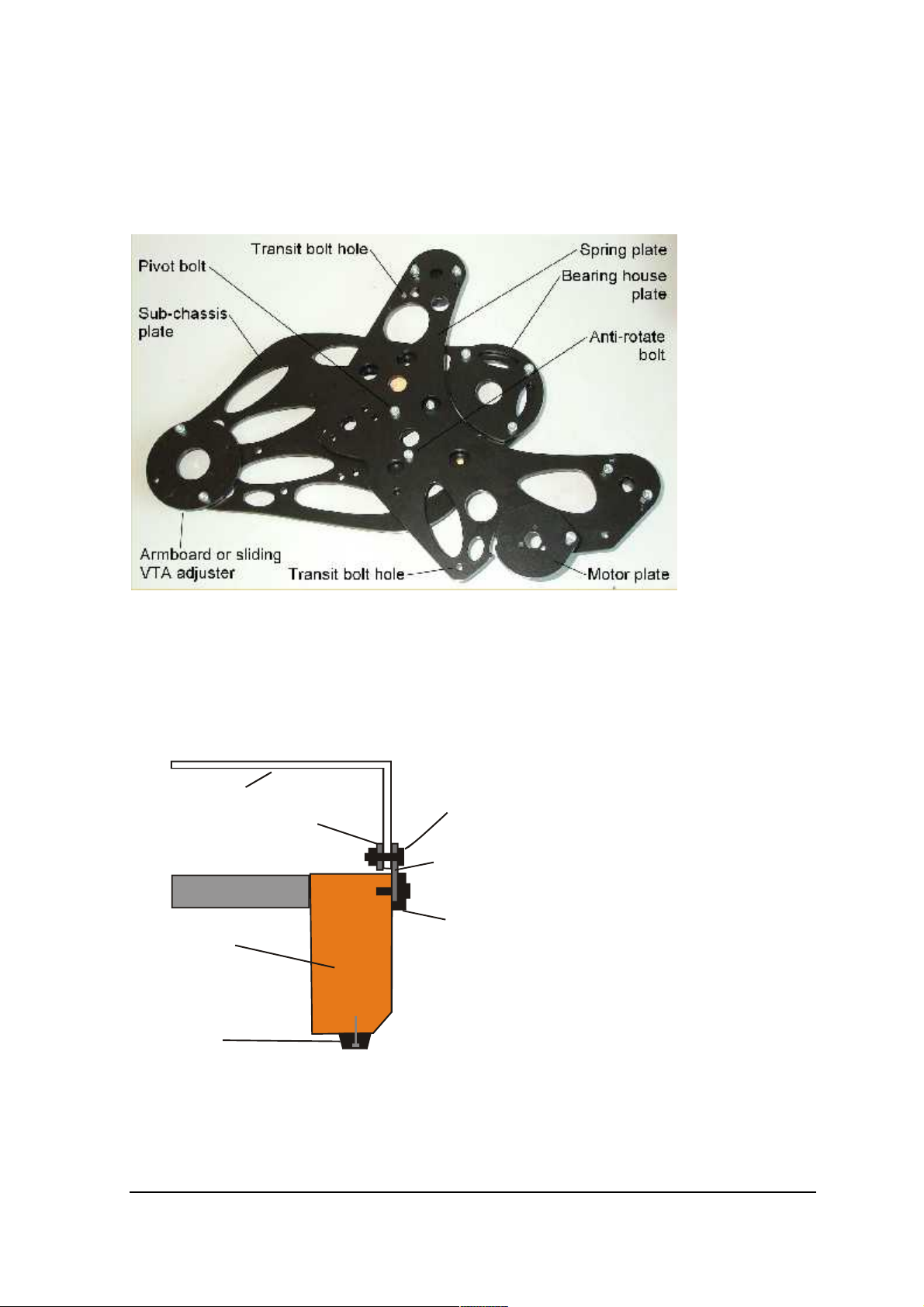
Fit Bearing house
Fit the bearing house to the sub-chassis as shown below - only "nip" the nuts tight with a pair of pliers - more force than
this is detrimental to performance - the top of the bearing house should be between 3mm and 8mm from the top of the
bearing house nut – 3mm is probably ideal. Please note that ALL the bolts on the Sub-chassis assembly are carefully
torqued to a correct tension at factory – DO NOT TIGHTEN ANY ALLEN BOLT SETTINGS OR IT WILL
DEGRADE THE PERFORMANCE. ”. The sub-chassis is attached to the “spring plate” by one “pivot bolt” - the two
plates should be free to swivel and are loosely restrained by an “anti-rotate bolt” - this locating bolt on the side of the
sub-chassis should not be tightened at all. The pivot bolt is tightened at factory and should not be tightened or the
performance will degrade significantly.
Diagram showing bearing house fastening arrangement
8
Page 9

Bearing House
Allen bolt
Spacing washer
Sub-chassis plate
Bearing plate
17 mm
Bearing house nuts
Bearing House
Fit the motor
Fit the motor to the motor plate using the 3 small machine screws supplied. These screws should be “just” tight to keep
motor noise to a minimum. The motor fits on the underside of the motor plate – see “diagram of sub-chassis assembly”.
The motor plate is adjustable to enable optimum belt tension to be achieved – The belt tension is set by rotating the
whole motor assembly on it’s pivot point. The motor is held in position by the friction of the pivot assembly. If for any
reason this becomes slack you may need to tighten up the pivot bolt. Ideally the centre of the pulley should be
approximately 124 mm from the centre of the bearing house. Generally the optimum position is such that marker bolt in
the “slot” is located at approx the mid point of the slot and this provides a useful reference point. Install Sub-chassis &
Fit springs
Fit the Sub-Chassis
Offer up the sub-chassis assembly into the plinth and fit the springs as shown in the “ diagram of support rods and
spring arrangement”. Each particular spring is of a different compliance and should be in the positions shown in the
“diagram showing spring positions
Diagram showing spring positions
THICK
SPRING
POSITION
MEDIUM
SPRING
POSITION
THIN
SPRING
POSITION
Dress the motor wires
Screw one of the cable clips onto the inner side wall of the left hand side of the plinth (see “top view of wiring layout and
connections”) such that it holds the input and motor wires (brown, blue, red & black) away from the sub-chassis and any
danger of restricting it’s movement. For full details on the motor and power supply set up read the relevant section
contained later in this manual.
Install the arm
It is necessary to fit the tonearm to the deck, before final “levelling” of the sub-chassis so that the weight distribution is
correct. At this stage the arm simply needs to be in position – it does not need to be adjusted for height or have the
9
Page 10

cartridge fitted etc.
If you do not have a VTA adjuster
If you do not have a VTA adjuster then bolt the arm to the armboard now - you only need tighten the large bolt to
finger tightness or very slightly tighter ("nipped tight 1/16 turn or less"). You will need to fit the arm “packing washer”
underneath the large bolt or it will not “clamp” on the 4mm thick armboard.
It is NOT recommended to place the large serrated washer (supplied by Origin Live with OEM Rega arms or
modification kits) under the large base nut as this does not work well with metal armboards.
If you have the Origin live threaded VTA adjuster (which fits all decks)
Thread the adjuster onto the arm. Ensure that the threaded metal sleeve is the right way up with the recess on the top
side. This ensures that the arm goes all the way down into the sleeve. It is NOT recommended to place the large serrated
washer (supplied with Origin Live OL1 arms or modification kits) under the large base nut as this does not work well
with metal armboards.
Bolt the arm to the armboard - you only need tighten the large bolt to finger tightness or very slightly tighter ("nipped
tight 1/16 turn" or less). You will need to fit the arm “packing washer” underneath the large bolt or it will not “clamp”
on the 4mm thick armboard.
If you have the Origin Live VTA sliding adjuster
Ensure that the Aluminium sleeve is the right way up with the recess on the top side This ensures that the arm goes all
the way down into the sleeve. Place the arm in the aluminium sleeve and then clamp it in position via the set screw in the
side of the VTA housing (i.e the sleeve is forced in to grip the arm’s threaded base). You do not need the Rega nut on
the base of the arm. Only tighten the set screw sufficiently to clamp the arm in position – over-tightening can make the
arm sound bright. Do not fit a threaded VTA adjuster if you have the sliding adjuster.
Fit the arm cable.
Fasten the arm cable - this should be supported by a cable clip screwed into position underneath the plinth - leave a
slight droop on it so that it isn’t “tight” (see diagram “top view of wiring layout & connections” for position). this is
helpful to minimise vibration of the cable. avoid pulling the external wires at the base of toneamrs as they are not
indestructible and can become detached if excessive force is used to manipulate them.
You can use one hole or two in the rear of the plinth to lead out the external cable. for thicker leads you will need to use
both holes. see picture “view of assembled kit from underside” at front of manual.
Fit the cartridge
If you are new to fitting hi-fi cartridges please see the notes provided under the heading “hi-fi cartridges - setting up
procedures” but do not carry out any fine tuning at this stage as you only need the cartridge bolted to the headshell for
arm height adjustment purposes.
Install the Sub-platter & Platter
With the syringe supplied, run approx 5 drops of oil into the top of the bearing house. Wipe the sub-platter spindle
surface to ensure that it is absolutely clean and very gently insert the sub-platter into the bearing house (If the oil does not
overflow when the spindle touches the bottom then try 2 drops at a time till you just achieve overflow - wipe away
excess oil) and then place the platter on top. The bearing needs a few minutes to “run in” and should run silent when
truly vertical and full of oil - if it doesn’t do so, there has probably been contamination with dust and you will need to
clean it out with a lint free paper towel or similar wrapped around a thin rod. If you do this, be sure to also wipe the oil
off the spindle as this also may contain microscopic contamination that is not visible.
Level up the platter using the nuts under the spring assemblies but only approximately at this stage. Ignore the fact that
the spring support plate is not level - it hangs at a slightly different angle to the actual sub-chassis that supports the arm
and platter - this is by design.
The top of the platter should be approx 31mm above the top of the arm board ( or top of the VTA adjuster if present).
Fit the belt over the motor pulley and sub-platter after cleaning all the running surfaces with methylated or surgical spirit.
Place the platter again on the sub-platter and level the platter by adjusting the nuts underneath the spring seats. Ideally
you should use a small spirit level for this purpose. You should also aim to get the top of the arm-board (or VTA
adjuster) roughly level with the top of the plinth top-board. Note that the sub-chassis should bounce freely without
contacting anything. It need only bounce up and down 1mm or so. Unlike some decks such as the LP2 you do not need
to achieve an “even” bounce - the Sub-chassis takes most of the weight on one spring so it doesn’t bounce very evenly.
Troubleshooting
10
Page 11

Please note that very occasionally the bearing house will not be truly vertical due to slight variations of the thread pickup
on the nuts. It is purely a matter of trial and error to get this right by rotating the nuts and bearing house slightly. Aim to
get the platter parrallel with the arm-board in at least the plane that affects cartridge “azimuth”. For definition of
“azimuth” see section on “hi-Fi Cartridges – setting up procedures”. You can always alter the height of the arm to get
the other plane true.
Be careful in moving or transporting the deck - it is possible to bend the spring supporting bolts if a severe side
movement occurs (bear in mind that the sub-chassis etc. is quite heavy). Ideally it is best to use the transit bolts to hold
the sub-chassis rigidly to the plinth topboard when transporting the deck. In the unlikely event of a sub-chassis foul on a
support rod, the answer is usually to bend the bolt to the correct position. Only resort to such measures after you have
checked all other possibilities such as springs not locating in their sub-chassis housings etc.
Connecting up the power supply.
Now that you have positioned the motor you need to plug in the control box and transformer.
Plug the smaller male dc connector from the motor into the left hand of the two holes at the back of the control box
(See Fig A below)
Plug the male dc connector from the transformer (low voltage input) into the right hand socket (when looking at the
back of the box) another way of describe it is the socket directly behind the LED.
You will know that the motor kit is connected up correctly when the LED comes on (This light will remain lit all the
time that the motor kit is plugged in at the mains supply).
The location of the control box should preferably be kept away from strong electromagnetic fields such as
those generated by transformers, amplifiers, power supplies etc.
view from front
Pow er LED
Rotary Speed
Control sw itch
view from rear
AA
Motor Output Mains Input
FIG A
Setting the motor speed
NOTE:
You will need to set the motor speed yourself. In the first 4 hours of use from starting up the motor, the speed tends to
drift but then settles down permanently. To burn in the regulator board components we recommend at least 4 hours of
running the motor before you accurately set the speed.
The thin output wires from the transformer only carry 8 volts and therefore safe to handle. Voltages inside the
transformer are dangerous so the transformer case should not be unscrewed or opened.
The switch box is designed such that when the rotary switch on the front of the control box is turned fully anti-clockwise
the motor is off. One click of the switch clockwise is 33.3 rpm and the second click clockwise is 45rpm.
NOTE: The speed can only be finally set or checked with the cartridge dragging on a centre track of a record as the drag
affects speed setting.
Instructions for reading the strobe
Place the strobe disc on the record to be played. Play the record and watch the relevant ring on the disc. Adjust the speed
11
Page 12

until marks on the ring appear stationary while the record is rotating. It sometimes helps to stare at infinity whilst doing
box you can identify P1 & P2 as they are labelled on
this as the marks become easier to see. You can see the strobe effect in florescent light although an ordinary bulb held
about 2 feet from the strobe disc will also work fine. The bulb flickers at 50 Hz in the EEC and 60 Hz in the USA.
If this photo is not quite the same as your control
You can purchase bayonet fitting florescent bulbs to fit normal lamps. Try to shut out daylight when carrying out speed
setting.
Set the speed
Adjust the motor speed as follows: using a small flat blade screwdriver turn the screws of the 25 turn resistors P1 and P2
the circuit board. Some boxes have the speed
adjusters on the rear of the box – in which case the
left hand screw is for 33rpm & the right hand screw
is for 45rpm (as you look at the rear face).
on the regulator board. These are accessible through the hole in the underside of the control box (See diagram below).
P1 is for the 1stspeed 33 rpm and P2 45 rpm. To increase speed, turn the presets clockwise. The pre-set screw will not
fall out and may need a fair number of turns to set the correct speed so keep turning until the speed changes. If the screw
reaches the end of it’s travel you can usually hear a faint clicking.
Set the switch on the control box to the first click i.e. 33 rpm setting.
Set P1 so that the platter turns at 33.3rpm. When setting the speed, place the arm on the centre track of a record so that
the cartridge is tracking the grooves this ensures that the drag of the cartridge is taken into account. Speed variations of
up to plus or minus 2% are quite common on decks and the dc motor is capable of plus or minus 0.1% accuracy. Use
the strobe disc provided to set the speed (full instructions are on the card). However if you have problems using the
strobe card, then count the rpm using the following method. Counting the 33.3 revs per minute is best accomplished by
placing a small piece of sticky tape on the perimeter of the platter and then counting 100 revolutions. 33.3 rpm is exactly
100 revolutions completed in 3 minutes. To save time in the early stages it is easiest to count 50 revs in 1 minute 30
seconds (or 25 revs in 45 seconds) and save the 100 count for the final check.
Please note the following points when setting the speed. Firstly all the figures below are based on setting the speed on
the deck using the centre track and letting the deck play for a good 5 minutes beforehand with the stylus on the record so
that the whole system has settled down. The regulators seem to take about 5 minutes to warm up, so speed is about
2mins 58 seconds for 100 revolutions when the system starts from cold. In other words it is 2/180 x 100 = 1 % fast
when started from cold. Speed variation with the dc motor varies minutely depending on the track played and cut of
record.
Click the rotary switch to the 2nd click clockwise and set P2 so that the platter rotates at 45 or 78 rpm (if you wish) using
the same procedure as outlined above.
The dc motors are noisy to begin with and are never completely silent in comparison to a/c motors. This is thought to
be due to a different type of precious metal brush. Having said this they still sound a great deal better in performance
terms. To assist "running in" you can turn the speed right up via the control box. The motor then runs at high speed.
Allow this for approx 4 hours. After the running in period reset the motor speed. The motor should then be run for
approx 3 days under load (i.e. turning the platter) to free it up from vibration and to “bed in” the bearings.
Like most turntable manufacturers we recommend that you leave the turntable running between changing records as this
reduces the belt wear that occurs with constant stopping and starting.
Notes on motor & speed setting
-Do not use the power supply for anything other than the dc motor or the power supply will definitely be irreparably
damaged and you could also damage the equipment you are plugging it into.
-The circuit will take around 8 hours to run in and sound it's best.
The speed stability of your deck should be excellent once everything has settled down in a listening session i.e.. The
power supply and switch box have been left plugged in on standby for 15 minutes, the platter has been turning for 2
minutes and the cartridge has been on the record for 30 seconds. Bear in mind that the ear detects when music is playing
slightly slow much more easily than it detects it playing fast. For this reason most manufacturers set their decks to run
slightly fast. You can expect a bit of speed variation when the motor is first switched on - it takes about 2 minutes to
12
Page 13

warm up properly and then the motor should run at it's correct speed but only when the stylus is on the record. It is
highly preferable to keep the transformer plugged in at all times (unless you are away on holiday) because it takes a good
15 minutes to warm up from cold and run correctly. When in standby mode the control box draws a negligible current
so you needn’t worry about your electricity bill.
If you keep switching the deck on and off you will get a little speed variation as it takes approx 2 minutes to warm up the
circuit each time even if it's only switched off for 3 seconds. This is unavoidable although we have tried to design out the
variation as much as possible.
If you measure the speed without a needle on the record the speed will not be perfect, as the speed should only be set
with the stylus tracking the record. If you don’t do this, the record will run slow once you put the stylus on the record.
If you measure the speed within 30 seconds of putting the needle on the record the speed will not be perfect as it takes a
while to settle down.
Some people make the mistake of constantly watching the speed before the deck has settled down and the needle has
been on the record for a good 2 minutes. Strobes are very accurate and the slightest speed variation is picked up. 0.03%
variation is observable which is over 30 times the accuracy of mid-priced decks on the market.
Final checks
Your turntable is now ready to use. The following checks make sure that you have set up the turntable
correctly.
The motor pulley must not foul the underside of the platter and should be inside the platter rim.
The tonearm should be set up with correct VTA i.e. the tube should be approx parallel to the surface of the record – see
the tonearm instructions about this as it is important to get the right sound and is often a matter of experimentation.
With the tonearm and cartridge mounted, check that the platter is level – if not, then level it by levelling the table or
surface that the deck stands on. If this is not possible then use a combination of the spring height adjuster and cork
disc(s) placed under one of the rubber feet of the deck. We understand that this may not seem the most elegant solution
but threaded adjusters would sacrifice sound quality significantly.
Ensure that there is a little “bounce” on the arm end of the sub-chassis. If not then check that the top chrome spring
adjuster is not touching the top of the spring support bolt, as this will render the whole suspension system ineffective.
Checking the sub-platter
The sub-platter spins freely and does not touch the bearing house or anything else.
If the sub-platter is rubbing on the top spring height adjuster you need to loosen the bearing house by unscrewing the
lower round bearing case – then thread the bearing house upwards and retighten. There should be at least 1-2mm
clearance between the spring top adjuster and the sub platter at all times.
Checking the platter
The platter spins freely and does not touch the motor pulley or anything else.
If the platter catches on the top of the pulley you can adjust the height of the bearing house by unscrewing it and
threading it upwards. This is very rare.
CHECKING THE MOTOR
Check that the motor housing is not touching the plinth at any point.
Check that the motor is tuned correctly as above.
Check that the belt is not rubbing on either of the flanges on the top and bottom of the spindle. If it does try tightening
the belt or see motor tuning.
Maintenance of turntable
To clean the deck, use a soft lint free cloth and wipe gently – if you have grease marks etc then you can use a generalpurpose anti-smear polish such as Mr Sheen but only if necessary – wax furniture polish is to be avoided and if possible
use an anti-static type of polish. Do not spray the polish on the turntable as it may clog up the cartridge etc but rather
spray it onto a soft polishing cloth and then use it on the turntable.
The Platter works best without any type of mat (including the Ringmat).
It is wise to keep the packing box that the turntable came in so that you can transport the deck securely. Be careful in
moving or transporting the deck - it is possible to bend the spring support bolt if a severe side movement occurs (bear in
mind that the sub-chassis etc. is quite heavy). Ideally it is best to remove the subchassis from the deck when transporting
the deck.
13
Page 14

14
The deck is not prone to going out of tune - we recommend that you check the level of the platter after the first few days
as the spring initially “beds in” and every year or so after this.
Depending on your use of the deck, the belt should ideally be replaced every 2 years or so.
If you withdraw the sub-platter spindle more than a few times you should put in a drop of oil to compensate for any
possible loss.
In the unlikely event that the support rod becomes loose over time such that it can “rocks” then the nuts need to be retightened. Only “nip” the nut tight by a maximum of 1/8th of a turn after finger tightness has been achieved and it
starts to clamp onto the steel.
Troubleshooting
Speed variation
If there is significant speed variation then possible causes are as follows.
Significant changes in room temperature - this especially affects decks that use thick, viscous oil in the bearings e.g. Rega
decks
Lack of oil in the bearing so check by adding oil.
Changed belt tension or an oily belt or sub-platter - clean running surfaces.
Turntable out of level – this affects the main bearing friction.
After adjusting the tension of the 3 small Philips screws which hold the motor on, you may need to re-adjust the speed as
they affect motor bearing friction very slightly.
Check the sub-platter is not fouling on anything - on certain decks it can rub against one of the spring covers - it has also
been known to "bottom" against the top of the bearing house - there should be about 1 to 3mm clearance between the
top of the bearing house and the bottom of the sub-platter.
A dirty bearing that exhibits too much friction - The sub-platter should drift round effortlessly with the slightest of
nudges and go on spinning. If you suspect the bearing friction to be a little high return the bearing to us for checking.
A worn thrust bearing - this may occur on a small run of bearings, which were too soft.
Transistors that have developed temperature instability.
Excessive motor noise
The motor needs a run in time of around 2 - 4 days continuous running. They are sometimes a little noisy to start with. It
is best to run in the motor on full power with the belt off. Most importantly you can "tune in" the motor to give
minimum noise by adjusting the tightness of the 3 small Phillips screws next to the motor pulley. The best way to set
their tension is to tighten the screws until they just nip tight. Then back off all 3 screws a little way. Now tighten one
screw at a time till you hear which ones cause the least noise when tensioned and then adjust the other two to give
minimum noise. It may be necessary to use thread lock or similar to stop the screws vibrating loose. If it continues to be
very noisy please get back to us and we may check it out. However bear in mind that the dc motor is never as silent as
a/c motors are - this is because they are cogless and rely on a different type of brush. Having said this dc motors still
sound a lot better in terms of musical performance.
The other major potential source of noise is the motor vibrating due to lack of tightness and causing it’s top plate to
resonate. The solution is usually to slightly tighten the 3 small screws holding on the motor. This adjustment is fairly
critical - if the 3 small screws are too tight then the motor whispers, too slack and the motor can vibrate against it’s top
plate.
Please note that by adjusting these screws you affect the angle of the motor. If the belt touches the flanges at the top or
bottom of the pulley then the motor is at too extreme an angle and you will need to re-adjust the bolts.
The ideal is for a vertical pulley with the lowest noise level. If you get a knocking sound from the motor then slightly
slacken off the 3 screws holding the motor to the top plate.
If you have checked the above and are still having trouble please contact us making a note of the serial number on the
back of the control box..
Final setup of tonearm
Installing the arm
Introduction
Rega arms and Origin Live arms require mounting dimensions such that the centre of the platter to the centre of arm
hole is approx 223mm plus or minus 2mm tolerance and the hole diameter for the arm is 24mm to 25 mm.
Page 15

Please note that for Origin Live Silver, Encounter and Illustrious tonearms - do not adjust bearing tightness - this is
GRUB SCREW POSITION
carefully set at factory - it may seem that there is “play” in the bearings - this is deliberate and must be left alone or
degradation will result - it is not actually play in the bearing races but careful bearing fitting to allow a loose bearing fit
thus “floating” the arm rather than rigidly coupling it to the deck.
NOTE
If you are fitting a Rega or Origin Live Arm to a kit that has the optional sliding VTA adjuster then you will only need
the sliding aluminium sleeve VTA adjuster, which is clamped in place by the single grub in the arm vta adjuster. None of
the large washers or the large nut, if they have been supplied, are needed.
If you are fitting the Arm to a kit without the sliding vta adjuster then you will need the packing ring and nut as shown
below – you may use spacing washers or our threaded VTA adjuster to obtain the correct arm height although you can
get away without them if you adjust the main bearing height instead.
IS HORIZONTAL
OPTIONAL THREADED VTA ADJUSTER
or spacing washers
for height adjustment
PACKING RING if threaded
VTA is used
SERRATED WASHER
REGA BASE NUT
ARMBOARD PLATE
VTA (vertical tracking adjustment)
To allow the cartridge needle to track at the correct angle it is important that the base of the arm is at the correct height
in relation to the platter.
For Rega arms, the OL1 series and Silver arm - Usually the optimum setting is such that the TOP edge of the
arm is parallel with the surface of a FLAT record – you can use a piece of card with parallel lines drawn on it to check
this once the cartridge is fitted.
For the Encounter, Illustrious and Conqueror arms – the centre line of the tapered arm tube should be parallel
with the surface of a FLAT record. You can use the template supplied to help judge this.
It is always best to experiment with vta height by varying it and listening to the results till you have found the optimum
position.
Most cartridges have a height of 17mm and if this is the case, then the base of the arm should rest approximately 31mm
below the top of the platter surface. If your cartridge height is different you can work out where the base of the arm
should be from the preceding figures.
Using the Origin Live VTA sliding adjuster
Do not fit a threaded VTA adjuster (supplied with some arms – this is a large knurled disc that can thread onto the arm
base). Ensure that the Aluminium sleeve (this IS the VTA sliding adjuster) is the right way up with the recess on the top
side. This ensures that the arm goes all the way down into the sleeve. Place the arm in the aluminium sleeve and then
clamp it in position via the set screw in the side of the VTA housing (i.e the sleeve is forced in to grip the arm’s threaded
base). You do not need the Rega nut on the base of the arm. Only tighten the set screw sufficiently to clamp the arm
firmly in position – over-tightening can make the arm sound bright.
Fit the arm cable clip
Fasten the arm cable in position with a nut & bolt through the cable clip. This should be supported by a cable clip
screwed into position underneath the plinth - leave a slight droop on it so that it isn’t “tight”. The clip fastens to the
underside of the plinth outer ring using the hole near the rear foot. This again is helpful to “earth” vibration in the cable.
(Please note that the occasional rewired arm can make a slight “rustling” noise through the speakers when it is lifted
across the record. This should not be a cause for concern as it is only caused by microphony of the internal litz cable under normal playing conditions this is inaudible. The earth lead should be connected to the earth of your pre-amplifier
or amplifier. This earth lead is best separated slightly from the arm signal leads so do not wind it around them for best
performance. Avoid pulling the external wires at the base of the Silver arms as they are not indestructible and can
15
Page 16

become detached if excessive force is used to manipulate them.
BALL BEARING
ALUMINIUM SLEEVE VTA ADJUSTER
THREADED ARM BASE
ARM MOUNTING PLATE
Arm & cartridge set up
Fit the cartridge (if not fitted already)
Fit the cartridge to the arm using an alignment gauge and ensure the headshell wires are bent so that they are clear of the
record surface. If you are not familiar with fitting cartridges then please read the section “Hi-Fi Cartridges – Setting up
procedures”.
Set tracking force & side force bias
TRACKING FORCE
Set the tracking force to the manufacturer’s recommendations using a stylus force gauge (stylus balance).
On all modified arms, Silver, Encounter Illustrious and Conqueror set the tracking force by sliding the counterweight
along the rear stub until the required tracking force is attained, then clamp up the grub screw in the side. When adjusting
the counterweight, set it so that the Allen bolt is at the side of the arm (not at the top) see figure “Rear end view of
counterweight” . You will need a stylus force gauge to measure the force underneath the cartridge tip.
HINT - In conducting this operation it helps to just lightly “nip” the allen bolt in the side of the counterweight onto the
stub – this way the counterweight has a little friction to hold it in position as you slide it backwards and forwards. Once
you have set the tracking force correctly you can firmly tighten the allen bolt in the counterweight to secure it tightly to
the rear stub then check that the tracking force is still correct after tightening.
On the OL1 tonearm which has not been modified (i.e it has a plastic rear stub with spiral groove) – You should turn the
counterweight till the arm balances level – once this is accomplished you can then set the tracking force by turning the
counterweight – half a turn = 1 gram.
Rear end view of counterweight AND ARM MOUNTING
GRUB SCREW POSITION
IS HORIZONTAL
(ARMBOARD)
PLINTH OR ARMBOARD
ALLEN GRUB SCREW
Use of Stylus force guage
Most stylus force gauges work on the same principle as a set of scales or balances. For example with the Ortofon Stylus
Force Gauge, first place the stylus on the inscribed or graduated portion of the scales. Then try the stylus at different
points until you find the point where the beam “balances” freely in a roughly level position. You then read the force that
is being exerted –( 1gram = 10 mN if the scale is in mN). From this number you can assess whether you need to
increase the tracking force or vica-versa. Move the tonearm counterweight accordingly and re-measure the tracking
force. Repeat this procedure until the correct tracking force is obtained. The Shure stylus force gauge works slightly
differently so follow the instructions that come with the gauge.
SIDE BIAS FORCE
Once the tracking force has been set you can set the sliding control for tracking bias - This should be set to a value of
approximately 1 or less due to the fact that the bias adjustments on Rega arms and similar arms tend to under-read the
true value of side force produced. . The settings you read on the Rega, OL1 or Silver arms are not always dead accurate
so it may be worthwhile to fine tune the setting using the following method. Find a test record or a record with approx
10mm of blank vinyl between the end of the lead out groove and the record label. Place the stylus needle on the blank
uncut vinyl and see whether the needle skates inwards towards the centre of the record or outwards. You are aiming to
achieve a situation where the needle drifts slowly towards the centre of the record so adjust the side bias until this state is
reached.
As the stylus tracks across a record it experiences forces that tend to push it towards the centre of the record. To
16
Page 17

counteract this force the arm is best set up with an approximately equal and opposite force called the “side bias”
On Rega, OL1 and Silver arms the side bias force is set using the small sliding knob located beside the lift lower lever.
On the Encounter, Illustrious and Conqueror arms – Carefully twist the wire loop to the correct angle relative to the arm
base – you can use the enclosed plan view of the arm to do this – the angle only needs to be approximate – the wire loop
is held in place by a set screw at it’s base – this can be retightened if necessary using the 1.5mm allen key supplied.
Carefully unpack the 2 balls and joining thread. Set up the 2 balls and thread as shown in photo below. The side bias
force is set using the ball which slides along the silver shaft protruding from the rear of the arm yoke (beside the
counterweight) - see photo below. This ball is clamped in position using a set screw in the ball with 1.5mm allen key.
Thread the thin nylon filament line through the small gap of the wire “eye” to allow the ball weight to hang freely. The
adjustment ball is initially set at just under three-quarters of the way out along the silver rod – this is approx the correct
position for most cartridges. If you wish to increase the side bias force then unclamp the ball using a 1.5mm Allen key
and the ball further outwards. To decrease the side force move the ball inwards. Once you have finalised the correct
position re-clamp the ball in position.
Set the VTA (vertical tracking adjustment)
To allow the cartridge needle to track at the correct angle it is necessary that the base of the arm is at the correct height in
relation to the platter. Usually the optimum setting is such that the TOP edge of the arm is parallel with the surface of a
FLAT record – you can use a piece of card with parallel lines drawn on it to check this. Place the cartridge on the record
with the deck switched off. Hold the card edge onto the record in a position alongside the arm and see whether the top
edge of the arm is parallel.. Raise or lower the base of the arm till you achieve parallel position. Most cartridges have a
height of 17mm. If this is the case, the base of the arm should rest approximately 31mm below the top of the platter
surface –see diagram “cross-section of sub-chassis”.
It is worth experimenting with VTA adjustment. Slightly raise or lower the arm and then listen - if the sound is relatively
bright then the arm is too high, if it is relatively dull and bass heavy then the arm is too low.
If you have no VTA adjuster Raise and lower the arm by fitting spacing washers under the arm. Alternatively you can
raise or lower the height of the platter – this is easily accomplished by removing the platter & sub-platter to re-set the
height of the threaded bearing house (see “diagram showing threaded bearing house arrangement”).
If you have the threaded VTA adjuster Raise and lower the arm by rotating the VTA adjuster. If you find your arm is
too high in relation to the platter with the VTA adjuster set to give the arm it’s lowest position then you need to raise the
height of the platter a few millimetres – this is easily accomplished by removing the platter & sub-platter to re-set the
height of the threaded bearing house (see “diagram showing threaded bearing house arrangement”).
If you have the Origin Live VTA sliding adjuster – Raise and lower the arm in the aluminium sleeve and then clamp
it in position via the set screw in the side of the VTA housing (i.e the sleeve is forced in to grip the arm’s threaded base).
You do not need the Rega nut on the base of the arm. Only tighten the set screw just sufficiently to clamp the arm in
position – over-tightening can make the arm sound relatively bright.
Set the arm fastening tightness
It is best to experiment with the tightness of the large Rega base nut (if fitted) by listening to music. This may seem
laborious but you will be richly rewarded as this adjustment is CRITICAL for performance. The mistake is often made
of over tightening this nut with the result that the music is deadened.
Warranty
We guarantee arms supplied by ourselves to be free from fault for 2 years and will undertake to correct any faults
providing the arm has not been modified by any party other than ourselves and has not received maltreatment of any
kind. Our OEM arms and modifications are not guaranteed by Rega so in the event of a warranty claim you should
contact ourselves rather than Rega.
17
Page 18

Notes
A detailed description of Cartridge set up and care is included in the end sections of this manual.
Please note that the occasional rewired arm can make a slight “rustling” noise through the speakers when it is lifted
across the record. This should not be a cause for concern as it is only caused by microphony of the internal litz cable under normal playing conditions this is inaudible.
Check that the arm can move freely across the whole record – if there is a “catch” then it is almost certain that the
curved arm rest is fouling on the yoke – simply rotate the arm rest till it no longer fouls – this can be carried out without
loosening the arm rest grub screw.
On the Illustrious and encounter tone-arms you can get a “gripping” action with the arm rest clip if you rotate it very
slightly so that it is at an angle to the arm ( not too much or you might get wear on the arm ).
The earth lead should be connected to the earth of your pre-amplifier or amplifier. This earth lead is best separated
slightly from the arm signal leads so do not wind it around them for best performance.
Now that all the hard work is over you can settle back and hear the results - we wish you many hours of enjoyable music
and rediscovering your record collection.
You can increase the height of the lift / lower arm rest by loosening the small allen screw in the side of the curved arm
rest and raising it slightly – finish by retightening it in position.
The sound of new arms and rewires will improve significantly over the first 2 weeks as items “bed in” and arm
wires burn in.
Fit the cartridge to the arm using an alignment gauge and ensure the headshell wires are bent so that they are clear of the
record surface. Ensure that the bias adjustment slider is set to zero. Set the tracking force to the manufacturer’s
recommendations using a stylus force gauge (stylus balance). When tightening the counterweight, set it so that the Allen
bolt is at the side of the arm (not at the top) see figure below and tighten firmly - check tracking force is still correct after
tightening.
It is worth experimenting with VTA adjustment if you can. Slightly raise and lower the arm and then listen - if the sound
is bright then the arm is too high, if it is dull and bass heavy then the arm is too low.
We guarantee arms to be free from fault for 2 years and will undertake to correct any faults providing the arm has not
been modified by any party other than ourselves and has not received maltreatment of any kind.
NOTE: The Ortofon stylus force gauge works on the same principle as a set of scales or balances. First, place the stylus
on the inscribed line on the white portion of the scales. Then try the stylus at different points along the line until you
find the point where the white plastic beam “balances” freely in a roughly level position. You then read the force that is
being exerted - 1gram = 10 mN on the numbered scale. From this number you can assess whether you need to increase
the tracking force or vica-versa. Move the tonearm counterweight accordingly and re-measure the tracking force.
Repeat this procedure until the correct tracking force is obtained.
A detailed description of Cartridge set up and care is included in the end sections of this manual.
H i - F i c a r t r i d g e s - s e t t i n g u p p r o c e d u r e s
I N T R O D U C T I O N
General comments
As we supply most makes of hi-fi cartridge we get asked questions from time to time about various issues regarding set
up and care. To help newcomers to this area we have published the following notes. These guidelines are of a general
nature - we publish them only to be of help and although widely accepted they are not formally authoritative - we cannot
accept liability if you choose to use them and neither do we encourage the time consuming occupation of answering
queries surrounding the procedures outlined - these are best referred to the manufacturer of your specific hi-fi cartridge.
For those new or inexperienced to fitting hi-fi cartridges we would state that this is NOT difficult and much of the detail
and perfectionism outlined below is for those who like to experiment. We ourselves do not normally check azimuth, or
vary tracking forces from the manufacturers recommendations - neither would we worry if the arm was up to 3mm away
from the recommended distance from the spindle - although all these details are audible they are generally of a fairly low
order, although tracking force and VTA are worth trying should you feel anything is lacking. If things seem complicated
we would encourage you not to be put off as it all becomes clear once you get started.
Before fine tuning the set up as described below you should allow the cartridge to "run in" properly - at least 40 hours for
some cartridges.
Importance of cartridge set up
Hi-Fi cartridges travel like a bobsleigh through the grooves of a record only a few thousandths of an inch wide. You hear
18
Page 19

groove displacements of the order of a few millionths. (That’s like splitting a hair into one thousand pieces.) Every bit of
motion or vibration allowed at this level can be heard enormously amplified through your speakers. For this reason it is
good to set up the turntable and arm correctly so that the audio cartridge can do it's job properly. For instance a turntable
out of level can produce side forces on the pickup cartridge tip that will wear it more on one side than the other as well
as have a slightly degrading effect on the wear of your records.
Levelness
When a turntable goes out of level, the platter bearing performance and the arm’s dynamics, specifically anti-skate, are
negatively affected. So be sure your turntable platter and tonearm mounting board are level - use a spirit level. If the
platter is out of level, first adjust the surface that the deck stands on. The suspension (in the case of a suspended subchassis design) may also need levelling if it has subsided over time.
Hi-Fi cartridges alignment
Alignment for hi-fi cartridges needs to be optimised in three different planes. However, it cannot be perfect in all three
planes, so it must be optimised for an overall best balance or compromise. The final authority should always be your ears
and preferably over an extended period of listening time. Bear in mind that each record is cut slightly differently. Here
again, optimise for an overall balance of good sound over a wide range of records. The three alignment planes are as
follows. (Please note that it is the stylus, not the cartridge that is being aligned.)
Lateral tracking angle
Viewed from above, the hi-fi cartridges arcing movement across the record must maintain the stylus in the same relation
to the groove as that of the cutting stylus’s straight-line tracking; this is Lateral Tracking Angle, or Tangency. Apart from
linear tracking arms this is always a matter of the best compromise.
Azimuth
Viewed from head on, the stylus must be perpendicular in the groove so as not to favour one groove wall, and therefore
one channel, over the other wall/channel; this is Azimuth.
Vertical tracking angle (VTA)
Viewed from the side, the stylus must sit correctly in the groove, at the same angle as the original cutter; this is Vertical
Tracking/Stylus Rake Angle. VTA, however, varies from record to record. Therefore, this alignment must be set by ear,
even more than is the case with the other adjustments).
Hi-Fi cartridge aligning tools
Tools required are an alignment gauge, a tracking force gauge, a FLAT record, a screwdriver or Allen keys of the right
size (usually 2mm), a good light may also be helpful. Small needle-nose pliers and a magnifying glass all help. It also helps
to have the hi-fi news test record. Treat the arm with care as some parts are fragile. To this end ensure that tightening of
any bolts is carried out gently and without causing undue strain.
Check hi-fi cartridge clip connections and mounting
Tonearm wiring uses a standard color code for left channel (L) and right channel (R) and polarity. Coding is as follows:
White = L Hot, Blue = L Ground, Red = R Hot, and Green = R Ground. If the cartridge pins aren't color-coded the
same way, they will have letter identifications next to them. Make sure that the arm’s wires, wire clips, and solder joints
are in very good condition. At minimum, clean the contact between cartridge pins and wire clips by removing and
replacing each clip. Holding the clips with needle-nose pliers can make this easier, but be careful that you don’t strain the
wires where they join the clip. Check the clips for a proper fit on the cartridge pins, and adjust them if necessary.
"Proper" means snug but not tight. To check clip size, hold the cartridge tail-up close to the head wires, grasp a clip
firmly right behind its tubular part with the tweezers, line it up with the cartridge pin, and press. If it does not slide on
with moderate force, the clip needs opening-up. If it slides on easily but flops around when attached, it needs tightening.
Sizing is the operation most likely to detach a clip. The trick is to avoid bending the wire at its attachment point or
putting too much tension on it. To avoid either, always hold the clip with its wire slightly slack-looped behind it while
adjusting. For opening a clip, hold it firmly with the tweezers or needle-noses, right behind its tubular section, and press
the tip of the jeweler's screwdriver into the open end of its longitudinal slot until you see this widen very slightly. (Here's
where you'll probably need the headband magnifier or reading glasses.) You're dealing with thousandths of an inch here,
so a barely visible spreading may be all that's needed. Try it for fit, and repeat until it does. For tightening a clip, press a
toothpick inside it as far as it will go, then use the needle-nose pliers to gently squeeze together the sides of the clip near
its free end, while watching the slot for any change. (Attempting to squeeze a clip without the toothpick inside it will
flatten its sides.) Try it for size, and resqueeze if necessary until the fit is correct. When it is, close up the middle section of
the tube to match the end
Cartridge mounting screws (usually 2.5mm allen bolts) should be tight. Steel allen bolts are the best for mounting hi-fi
cartridges - aluminum or brass are OK but difficult to tighten up hard (as they should be).
Setting up hi-fi cartridges
19
Page 20

Mounting
Mount the hi-fi cartridge in the headshell if this is not done already. This is best done with the hi-fi cartridge stylus guard
in place but it may be necessary to remove it during at least one phase of the installation. If you do, replace it as soon as
possible. Be especially careful when the stylus guard is off, as many MC cartridges have a strong magnetic field at the
base of the cantilever. If this attracts the tip of a steel-bladed screwdriver, it can destroy the stylus - there is no hope of
resisting it. The best precaution is to keep the screwdriver well away from the cantilever, use a nonferrous screwdriver, or
keep the stylus guard on when you're using the screwdriver near it. The other main hazard is children so don’t forget to
warn prying fingers.
The headshell screws should be finger-tightened just enough that the cartridge cannot fall off but still loose enough that
the cartridge is easily moved around. Work whenever possible with the stylus’s safety cap in place. Set tracking force at
nominal, then do the tangency alignment procedures, then the azimuth. Do not deviate from this sequence as each step
affects the subsequent one — change the order and the setup will be wrong.
Tracking Force
This adjustment is carried out on the counterbalance weight of the tonearm or spring dial if one is in place. At this point,
use your tracking force gauge and setting tracking force according to your cartridge instructions — final adjustment will
be done later by ear.
If you do not have a tracking force gauge, but the arm does have a calibrated counterweight, defeat the arm’s anti-skate
mechanism or set it to zero. Set the counterweight so the arm is level and balanced. Be very careful of the unprotected
stylus — you cannot do this with its safety cap in place. Once the arm is balanced, lock it in its cradle and, using the
calibrated counterweight, set the tracking force according to your cartridge’s recommended weight.
Tangency Alignment
(lateral tracking angle) - Follow the manufacturer's literature and the dictates of your alignment gauge — different gauges
use slightly different methods. As you square up the hi-fi cartridge body with the gauge’s markings, be sure that the
cartridge sides are square or your alignment will be wrong. When all adjustments are correct, carefully tighten down the
hi-fi cartridge mounting screws. Keeping a firm grip on hi-fi cartridge and headshell together so nothing shifts, delicately
tighten each screw down a turn or so, then repeat until tight. Tightening down one screw all the way before tightening
the others is almost certain to twist the cartridge out of alignment. However careful you’ve been, always check the
alignment again after tightening.
Vertical Tracking Angle (VTA)
Unless your tonearm has a special VTA adjuster, adjusting arm height is usually carried out with the use of spacing
washers (as with Rega arms). In arms with a pillar / collar type vta adjuster it helps to put pencil or pen marks on the
pillar to keep track of various heights. See your tonearm manual for its recommendations on adjusting arm pillar height.
The best approach is to tune-in VTA gradually by listening to music. You know the arm needs to be lowered at the arm
pillar when the overall sound is hard and bright, with thin bass or no deep bass, edgy highs, and harsh midrange (of
course, this could also be tracking force which is too light). Distortion obscures low level details between the musical;
notes so dynamic range is reduced. Transient attacks may be too sharp. Raise the arm when the sound is dull and
damped, the highs rolled off, the lows muddy and lacking definition, and transient attacks are dull. Mind you, this sounds
an awful lot like the effects of changes in tracking force (too light is edgy, too heavy is heavy and dull). They are different
sounding but hard to explain. Start with the arm a little low and very gradually raise it, first to where it is parallel to the
record, and then so the back of the cartridge is tilting up. Keep track of your settings so you can return to the one you
like best where everything snaps into focus. The range of adjustments can be quite broad, as much as 3/4" or even more
(at the arm pivot). Play with the full range so you know what it sounds like and don’t be diffident.
Antiskate Force (pivoting arms only)
This applies an opposing, balancing force to the natural inward drag of a pivoting arm while playing. Left uncontrolled,
the stylus would push up against the inner groove wall, causing distortion both from mistracking and a cantilever skewed
in relation to the cartridge generator. To set, lower the stylus down near the label of a record with a wide run-out to it.
Increase antiskate until the arm starts to slowly drift outward, away from the label. Again, this should be finalized by ear
as you listen to music. If image placement is a little off-center, or if things don’t seem to be locked in solidly, experiment
with antiskate. Also, watch the stylus when you set it into a groove. Does it move to the right or left relative to the
cartridge body? This indicates too much or too little antiskating.
Fine Tuning
You now have three adjustments approximated. Tracking force, VTA, and azimuth. It’s a matter of reiteration to
optimize the sound. The change in sound with each of these individual adjustments can be similar. It’s therefore
necessary, in optimizing all three, to experimentally move from one type of adjustments to the next, then to the next, in
order to balance the optimization for all three. It's helpfull to listen to female vocals as you proceed. Firstly try deviating
from the cartridge’s recommended tracking force by small increments - about 0.2 of a gram deviation above and below
the manufacturer’s basic recommendations. Don’t worry about record damage from heavy tracking as most record
20
Page 21

damage is actually caused by mistracking in the middle-to-high frequencies with too little tracking force rather than with
too heavy. If you’re getting mistracking at the low (lightest) end of the range and yet the low range is generally sounding
the best (and on moderate signals, not heavy passages), then chances are you have either a dirty stylus, a bad record, an
accumulation of crud in your cartridge, or a cartridge that’s getting old. Changes in tracking force can change how you
want VTA and azimuth adjusted. If azimuth was initially adjusted by ear, experiment with it.
21
Page 22

Proper care and maintenance of Hi-Fi cartridges & records
Care of hi-fi cartridges
Replace your cartridge when due - hi-fi cartridges have a lifespan for their cantilever suspensions and stylus needles. This
will vary from manufacturer and type of cartridge as well as other factors like the cleanliness of your records and the care
you take of the cartridge. It is wise to enquire on the expected life of your cartridge to the manufacturer, so that when the
time comes it is replaced accordingly - most importantly this will preserve your records as well as enable you to enjoy the
best performance.
If there is a build-up of dust and dirt where the needle enters the cartridge body you should use a small soft brush to
brush the debris out. Always brush from the direction of the cantilever to the stylus or you may do damage.
Care of stylus - One well known method of cleaning stylii is the Linn green stuff which is a very fine abrasive paper - this
may is OK on some cartridges which do not have fine stylus tips and fragile cantilever mechanisms. However there is a
danger of causing fractures or chips in your diamond stylus on certain fineline tips. This method can also strain the
cantilever mechanism.
There are a number of fluids on the market that increase stylus life and help to clean gunge from the needle - a word of
caution though - some of these can loosen the stylus glue on the cantilever over time - some fluids can also attack the
cantilever or coil material itself or harden the suspension - consult your cartridge manufacturer over this. One key factor
is to use the liquid very sparingly on a cotton bud such that it is just damp (not running with fluid) - this minimises the
fluid which can run up inside the cartridge.
Record care and cleaning
The stylus itself does a pretty good job of cleaning the grooves and should itself therefore be kept clean. The proprietary
brushes etc. for cleaning records will often do little more than brush dirt deeper into the record grooves and are best
avoided if possible. Also keep records in high quality non-scratch record sleeves - preferably good ones.
A record cleaning machine is really the only answer for cleaning records properly as they suck out the debris and dust in
the record grooves using a powerful vacuum. Tests using a microscope prove that this does the job with 100% success.
The performance improvement is also very noticeable when it comes to even new records being played. We supply and
highly recommend the Moth record cleaning machine as this is very effective from personal experience and comes with
many glowing endorsements – see our web site for details and reviews.
22
Page 23

ORIGIN LIVE, Unit 5, 362b Spring Road, Sholing,, Southampton, SO19 2PB U.K.
Tel:- 02380 578877 Fax:- 02380 578877 Owner:- Mark Baker C.Eng, BSc(Hons)MRINA
e mail: originlive@originlive.com web site: http://www.originlive.com
23
 Loading...