

Page 1

***essential reading***
Instructions for
MK3C - Encounter , illustrious & Conqueror
INSTRUCTIONS BY ORIGIN LIVE 10/2011 ©
PLEASE NOTE: The sound of new arms
and rewires will improve signifi cantly over the
fi rst 2 weeks as items bed down and arm wires
burn in.
Introduction
Thank you for ordering from Origin Live. We trust you will enjoy
getting closer to the original sound and appreciating your music in
a new way.
Please give special attention to underlined text in these
instructions. First of all, note that it may seem there is “play”
in the bearings - this is a design feature and bearing tension
should not be altered or degradation will result - The bearings
on the vertical axle are high quality, however the vertical bearing
house is carefully dimensioned to allow a slightly loose fi t, thus
“fl oating” the arm rather than rigidly coupling it to the deck.
Mounting the arm
If possible, refer also to the mounting instructions from your
turntable manufacturer.
Arm mounting methods vary depending on the make of your
turntable. This section caters for various scenarios.
Mounting hole dimensions
Some decks come with an arm hole position specifi caly set up
for arms with “ Rega “ geometry. If this is not the case with
your deck, then Origin Live arms require centre of platter,
to centre of arm hole, to be approx 223mm (222.7 precise )
plus or minus 2mm tolerance. The hole diameter for the arm
is 23mm to 25 mm (23mm will accept the arm but not a
threaded vta adjuster.
arm to fi t, please refer to our web site FAQ (frequently asked
questions) in the tonearm section.
Mount the arm in the armboard as shown in the illustration
below. You can raise the arm height to approximately the right
level using vta wheel for fi ne adjustment.
24 - 25mm ARMBOARD HOLE WITH VTA
ADJUSTER
GRUB SCREW POSITION
IS HORIZONTAL
THREADED VTA ADJUSTER
Do not t normaly
ARM
CORK WASHER
THREADED ARM BASE
If you have the Origin Live threaded VTA adjuster, this should
be threaded onto the tonearms base post BEFORE you fi t it
through armboard (VTA adjuster fl ange on top). You can
later adjust the height of the arm by adjusting the turns of the
threaded vta adjuster
ARM MOUNT SURFACE
LARGE CLAMPING NUT
A threaded VTA adjuster should not be needed except in very
rare instances where the integral VTA adjuster wheel cannot
raise the arm high enough. If a threaded VTA adjuster is
needed as a last resort to raise the arm then the hole must be
24 - 25mm).
If you need to modify your existing armboard to enable an
As a rule of thumb you will fi nd the best tension on the nut is
just a little more than fi nger tight. Just tighten to fi nger tight and
use a spanner, pliers or molegrips to “nip” the nut a tiny fraction
tight, Do not overtighten the arm as it is counterproductive..
Page1
Page 2
Understanding dual Pivot
Your Origin Live arm has innovative bearings. is is best
explained before going any further.
Dual pivot bearing design – why?
One of the many reasons that the Origin Live arms are
performance leaders is due to the dual pivot bearing,
on the horizontal axle (which governs the arms vertical
movement). e design is similar in many respects to
uni-pivot – low friction and high decoupling which give
excellent de nition and transparency. However unipivots can be ddly to set up and because of their relative
instability exhibit a mediocre bass performance. Dual
pivots have all the advantages of uni-pivots but none of
the drawbacks. Vertical movement of the arm is handled
by the dual pivot and horizontal movement by our usual
highly speci ed conventional bearings.
already been set, such that the headshell is parallel to the
arm mounting surface. We strongly recommend that you
never adjust the factory setting without our permission, as
this will invalidate the warranty. Correct azimuth setting
is tricky at the best of times and unless an extremely
careful record is kept on the original factory settings the
arm will probably end up not working correctly.
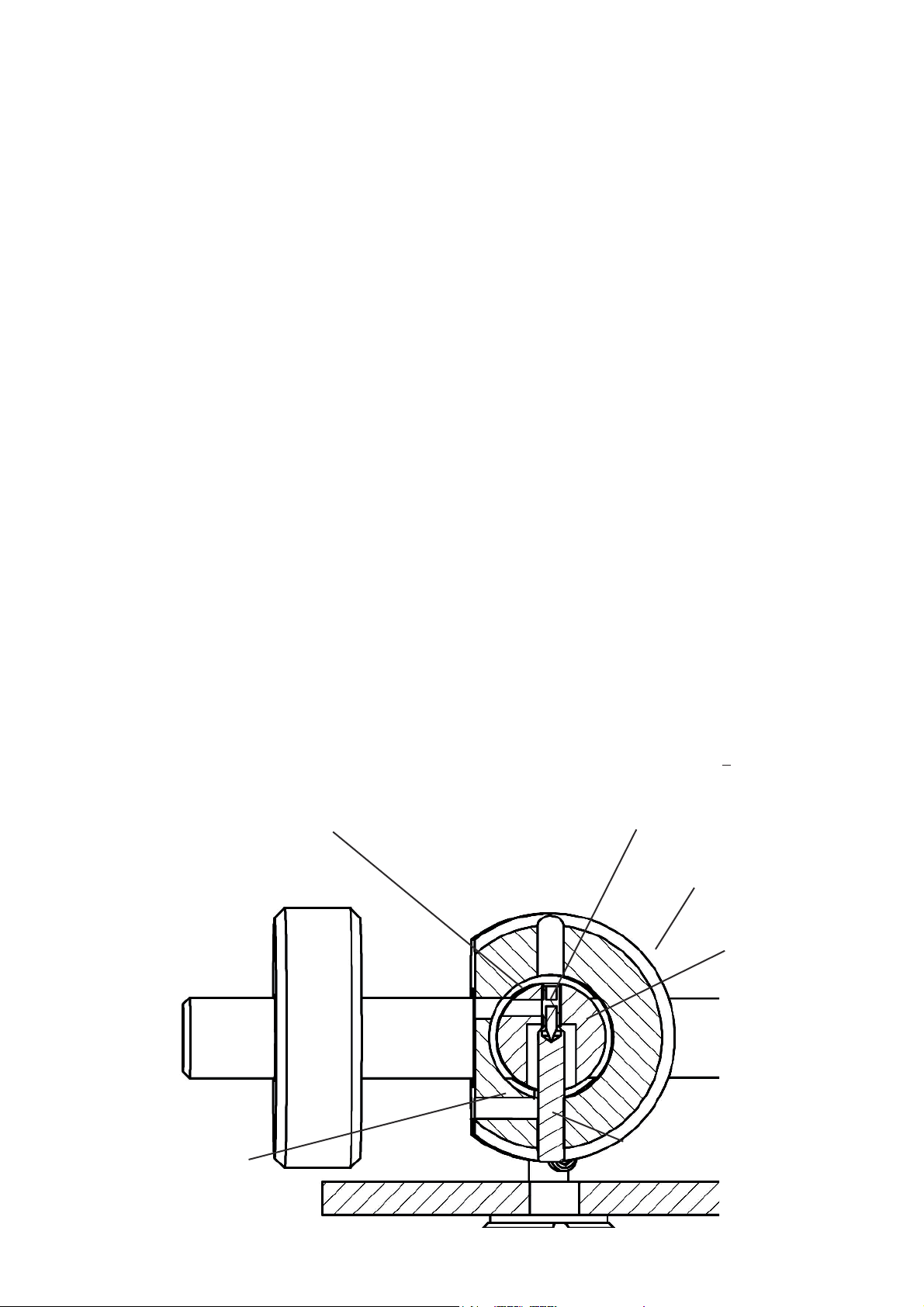
How dual pivot works
e below illustration of the dual pivot bearing shows
how the horizontal axle is free to move a little in all
directions except downwards. is may be a little
disconcerting until you become con dent of the inherent
performance virtues delivered by this approach. It is also
reassuring to know that the arm cannot be knocked o it’s
bearings or come loose in any way. You can turn the arm
upside down and nothing will fall o as it would in the
case of a uni-pivot!
Floating bearings for horizontal rotation
ere is a certain amount of “rocking movement” on
the yoke vertical axis. Some people mistake this for poor
bearing t but this is far from the case. Whilst most
arms use “rigid” bearing ts, Origin Live is unique in
employing a “ oating” bearing design - this is actauly
much harder to engineer and does not cause alignment
errors as the bearings are self centering and factory
settings of the headshell take account of this.
Handles like a conventional gimballed
arm
You should handle the arm in exactly the same way as a
conventional gimballed arm. In other words you do not
need to worry about setting up azimuth. e azimuth has
SPIKE CLAMPING SCREW
Do not touch
e pivot bearings are designed to reduce friction to an
absolute minimum. In doing this there is a ne balance to
achieve both a robust design whilst maintaining extremely
low friction. In practice, the arm must have a slight degree
of movement due to a sharp tungsten point in a shallow
radiused bearing cup. e alternative to this is a very
sharp point in a deep v shaped cup – this would certainly
restrain the movement of the point but would also
increase friction and potential fracture of the tips.
e pivot points will “self centre” by sliding into the
bottom of the bearing cup. However the nal resting
place of the point may vary by 0.01mm or so. is would
not be noticed without the use of a very accurate digital
stylus force gauge.
As the pivot position shifts fractionally it can cause the
tracking force to vary slightly, by around +0.06 grams
THREADED SPIKE
YOKE BARREL
PILLAR
CLAMPING
SCREW
Do not
touch
END CAP
PILLAR CUP BEARING
Page2
Page 3
from an average reading. In practice this has no e ect
on performance and is also common among certain
unipivot designs with very low friction bearings.
force should be consistently accurate to within plus or
minus 0.06 grams from the average (i.e = 0.12 gram
total variation). Higher deviations indicate that the
bearing might be damaged or incorrectly adjusted.
Connecting the arm
FIT THE ARM CABLE CLIP
For best performance the arm cable should be
supported by a cable clip screwed into position
underneath the plinth - leave a slight droop on it so
that it isn’t “tight”. Clipping the arm helps prevent
vibration feeding into the arm.
CONNECT THE ARM TO YOUR PHONO
STAGE / AMPLIFIER
e bullet phono plugs are usually a very tight t to
your phono stage sockets. To avoid possible damage
to your ampli er sockets, the manufacturers advise
that you should heat the bullet plugs with a hair dryer
(or similar) to soften them slightly till they t easily
onto your phono stage / ampli er phono sockets.
Once tted, you do not need to reheat the plugs in
future as they will maintain the correct tightness.
e earth lead should be connected to the earth of
your phono stage, pre-ampli er or ampli er. is
earth lead is best separated slightly from the arm
signal leads so do not wind it around them for best
performance. Avoid pulling the external wires at the
base of the arm as they are not indestructible and
can become detached if excessive force is used to
manipulate them.
e bearing freedom of movement should be checked
by measuring the stylus down force over a succession
of 10 or so movements of the arm into the arm clip
and then onto a stylus force gauge. e force gauge
should read consistently to within plus or minus 0.06
grams from an average over the 10 measurements if
all is well.
It is best to use a digital force gauge for this as a
“balance” type can give inconsistent readings with
errors of up to 0.5 grams .
TRANSIT BOLTS WITH NYLON
WASHERS UNDERNEATH
Remove and keep for future use
If you have XLR plugs, you will not get both plugs
through the mounting hole for the arm. e hole is
too small to allow the 2nd plug to go through as the
1st cable wire takes up space.
For this reason we normaly t only one XLR plug
and leave you to t the other. Full instructions on
how to t the other XLR are available on our web site
- see top navigation bar, click “general information”
then “technical support” on the drop down list.
Making the dual points
operational
e transit bolts shown in illustration are critical,
to prevent damage to the bearing points in transit.
Gently remove these to make the arm operational.
Keep the bolts and nylon washers in a safe place.
ese MUST be replaced whenever you send the
arm by post or courier as the boxes can get severely
thrown around. Damage to the points occurs, unless
the transit bolts are in place.
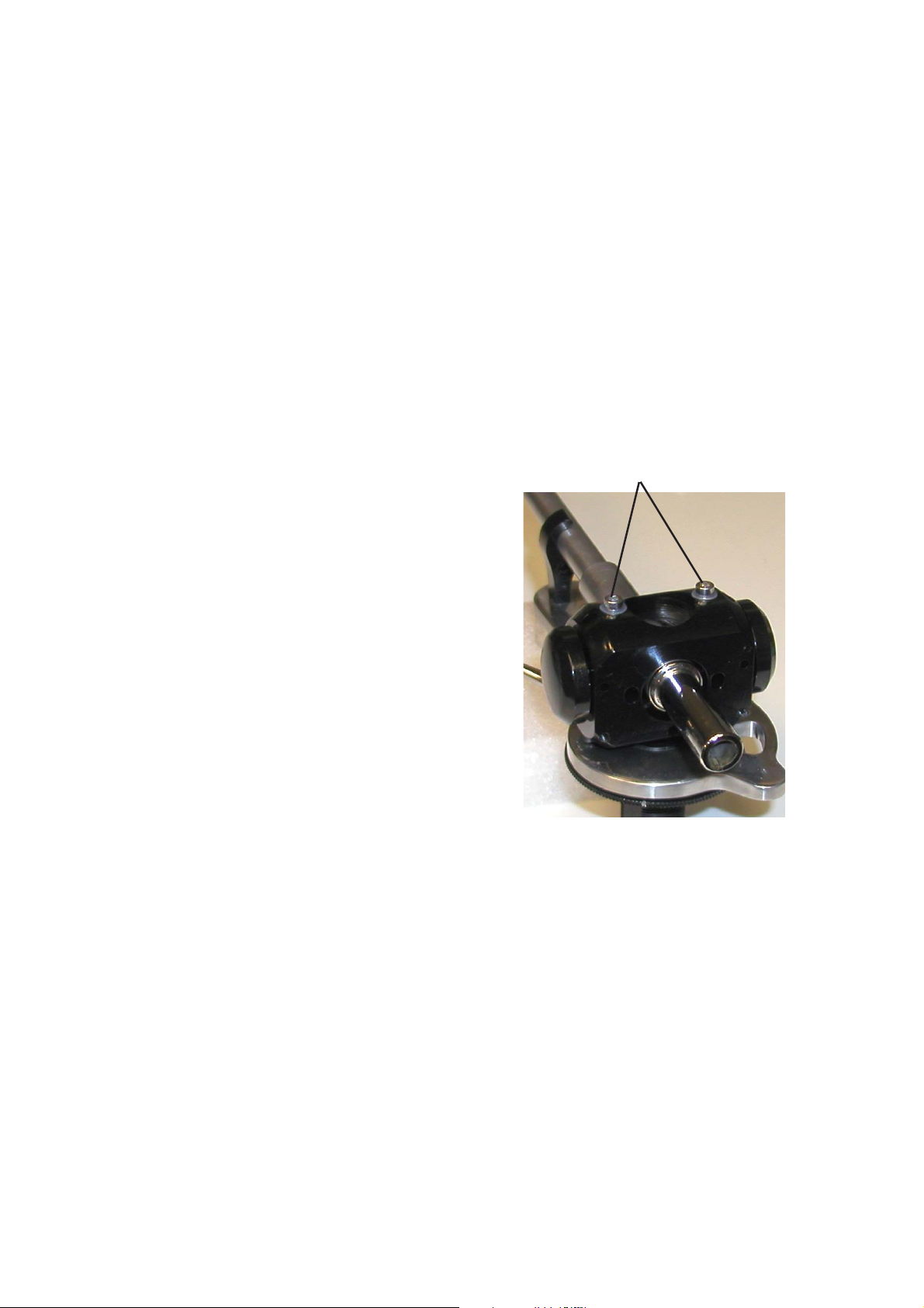
DO NOT TAMPER WITH ANY OF THE GRUB
SCREWS IN THE YOKE - ese are precisely set up
at factory and any interference will probably end up
with damage to the pivot points or bearings that don’t
work properly.
CHECK THAT ALL IS WELL - e stylus down
Page3
Page 4

Fitting the counterweight
It is best to t the counterweight at this stage. e
downforce on the cartridge is set by clamping the
large counterweight to approximately the correct
position on the rear stub. e trick here is to lightly
nip the grub screw when it gets close to giving your
desired tracking force setting. You can then gently
twist it slightly while pushing it in the desired
direction till it gives the correct reading. Once this is
achieved, clamp up rmly and recheck the reading.
e ne adjuster is not supplied unless speci cally
ordered - it can be ordered at a later date but is
not generally used as it degrades performance
slightly. If you have the ne adjuster, then once the
counterweight is rmly clamped in approx the right
position, nal adjustment is carried out using the
ne adjuster on the rear of the counterweight - see
illustration below.
nger-tightened just enough that the cartridge cannot
fall o but is still loose enough that the cartridge is
easily moved around. Work whenever possible with
the stylus’s guard in place. Now carry out the set
up procedures outlined below. Do not deviate from
this sequence as each step a ects the subsequent one
— change the order and the setup will be wrong.
SET TRACKING FORCE
Set the tracking force to the cartridge manufacturer’s
recommendations using a stylus force gauge (stylus
balance). is will need to be re-set later on so do not
worry about getting it too exact at this stage - within
0.3 grams of recommended tracking force is ne.
First screw in the ne adjuster on the rear of the
counterweight as far as possible. Now set the tracking
force to within 0 to 0.35 grams OVER the correct
reading using the grub screw in the side of the major
counterweight. Do this, by sliding the counterweight
along the rear stub until the required tracking force
is attained, then clamp up the grub screw so that it
locates in the groove in the side of the rear stub. i.e
When adjusting the counterweight, set it so that the
Allen bolt is at the side of the arm (not at the top)
see gure “Rear end view of counterweight”. You
will need a stylus force gauge to measure the force
underneath the cartridge tip.
Allen grub screw to
clamp large weight
Fine adjuster weight to give
0.35grams adjustment.
Cartridge set up
If you are not familiar with fi tting cartridges then please read the
detailed section “Hi-Fi Cartridges explained” found towards the
end of this manual.
MOUNTING
Mount the cartridge in the headshell of the arm.
Cartridge mounting screws (usually 2.5mm allen
bolts) should be tight. Stainless steel allen bolts are
the best for mounting hi- cartridges - aluminum or
brass are OK but di cult to tighten in comparison to
allen heads. Avoid steel bolts as they are magnetic and
degrade your cartridge magnets.
is is best done with the stylus guard in place but
it may be necessary to remove it during at least one
phase of the installation. If you do, replace it as soon
as possible. Be especially careful when the stylus
guard is o , as many MC cartridges have a strong
magnetic eld at the base of the cantilever. If this
attracts the tip of a steel-bladed screwdriver, it can
destroy the stylus - there is no hope of resisting it. e
best precaution is to keep the screwdriver well away
from the cantilever, use a nonferrous screwdriver,
or keep the stylus guard on when you’re using the
screwdriver near it. e headshell screws should be
HINT - e counterweight is deliberately a very
loose t on the stub for best performance. Because of
this, it helps to just lightly “nip” the allen bolt in the
side of the counterweight onto the stub – this way
the counterweight has a little friction to hold it in
position as you slide it backwards and forwards. Once
you have set the tracking force correctly you can
tighten the allen bolt in the counterweight as rmly
as possible to secure it tightly to the rear stub. Recheck that the tracking force is still 0.3 to 0.35 grams
over the manufacturers recommendation.
USE OF STYLUS FORCE GUAGE
Most stylus force gauges work on the same principle
as a set of scales or balances. For example with the
Ortofon Stylus Force Gauge, rst place the stylus
on the inscribed or graduated portion of the scales.
en try the stylus at di erent points until you nd
the point where the beam “balances” freely in a
roughly level position. You then read the force that
is being exerted –( 1gram = 10 mN if the scale is
in mN). From this number you can assess whether
you need to increase the tracking force or vica-versa.
Move the tonearm counterweight accordingly and
re-measure the tracking force. Repeat this procedure
until the correct tracking force is obtained. A digital
force gauge works slightly di erently so follow the
manufacturer’s instructions.
SET TANGENCY ALIGNMENT (LATERAL
TRACKING ANGLE)
First of all set the cartridge overhang, which is 17mm for
all Origin Live and Rega arms. The overhang of the cartridge
Page4
Page 5

is the measurement from the centre of the spindle to the tip of
the cartridge stylus when the armtube is positioned such that it’s
centre line is directly over the centre of the spindle. Whenever
you rotate the cartridge to align it, the overhang position must
be maintained and checked at the end of the whole procedure.
Follow the manufacturer’s literature and the dictates of your
alignment gauge - different gauges use slightly different methods.
Square up the hi-fi cartridge body with the gauge’s markings, be
sure that the cartridge sides are square or your alignment will be
wrong. When all adjustments are correct, carefully tighten down
the hi-fi cartridge mounting screws. Keeping a fi rm grip on hifi cartridge and headshell together so nothing shifts, delicately
tighten each screw down a turn or so, then repeat until tight.
Tightening down one screw all the way before tightening the
others is almost certain to twist the cartridge out of alignment.
However careful you’ve been, always check the alignment again
after tightening.
VT A Adjustment
To allow the cartridge needle to track at the correct VTA (vertical
tracking angle) it is important that the base of the arm is the
correct height in relation to the platter.
The top or bottom edge of the tube should be roughly parallel
with the surface of a FLAT record. You can use the template card
supplied to help judge this.
It is always best to experiment with vta height by varying it and
listening to the results till you have found the optimum position.
This is necessary because of manufacturing variations in stylus
angle tolerances.
VTA (VERTICAL TRACKING
ANGLE) ADJUSTER WHEEL
Ensure the headshell wires are bent so that they are clear of the
record surface.
Adjustments for vta & tracking force
Ignore minor differences in your arm to below drawing which is for illustration only
DO NOT ADJUST ANY OF THE SET
SCREWS IN THE YOKE BARREL SECTION
VTA Calibration: The arm must be “unclamped” for the
vta wheel to work – see diagram for “vta clamping grub screw”
COUNTERWEIGHT
CLAMPING SCREW
Best on SIDE as shown
VTA HEIGHT ADJUSTER WHEEL
Half turn clockwise raises arm 0.5mm
Must slacken VTA clamping screw
before turning.
Re-clamp after adjusting to your
preferred tension
VTA CLAMP SCREW
Tighten up hard once vta is set.
Loosen when adjusting VTA
Do not adjust any other set screws
on this level
Do not adjust screw on
opposite side of VTA
clamping screw
Page5
Page 6

and slacken it half a turn or so.
Just under the arm plate is the thin silver vta height adjuster
wheel – To raise the arm, turn the wheel clockwise (anticlockwise to lower it). The wheel has a dimple so that you can
see how far you turn it - each half revolution of the wheel is
equivalent to a 0.5mm change in height.
Clamping: For the sake of speed in vta setting, we
recommend that you leave the arm unclamped during the
comparisons. However it will sound FAR better clamped,
once you have arrived at the vta “sweet spot”. An Allen key
is provided for this purpose and the position of the clamping
grub screw is shown in the relevant diagram.
The wheel is capable of raising the arm around 30mm but not
more than 20mm is recommended for optimum performance.
The following calculations are given to try and give a sense of
proportion to a rather intuitive but incorrect notion.
Inertia differences are relatively insignifi cant. To get the weight
closer to the pivot, the counterweight has to be heavier and
this adds inertia - all in all a difference of 20mm or so is not a
big deal.
To illustrate this using laws of physics - the moment of inertia
is m x r squared where m is the mass and r is the distance to its
centre of rotation
Say that a 130gram counterweight is 45mm away from the
pivot - moment of inertia is 0.13 x 0.045 squared = 0.26 x10
to the minus 3
Experiment with vta: It is important to experimentally set
the optimum arm height by listening to different vta settings.
If the arm base is too high, the sound is usually slightly on the
bright side and lacking body in the bass – too low and it veers
on the dull side. To enable precise and repeatable vta setting,
your Origin Live arm has an integral vta adjuster wheel. This
method of height adjustment is extremely accurate, with
obvious benefi ts in terms of speed of adjustment. This means
better listening comparisons between different vta settings.
Do not adjust Azimuth or any of the point settings
in the yoke
The adjuster points are set up very accurately in the factory for
correct azimuth. This is a very fi ne adjustment and one that
needs specialist knowledge of the arm. For this reason if any
of the grub screws are adjusted in the yoke other than by an
authorised dealer it will invalidate the warranty.
Counterweight position too near the
end of the stub? (optional read)
A common idea propogated in Hi Fi circles is that the
counterweight should be as close as possible to the yoke to
minimize inertia and reduce “see / saw” effects over record
warps. We believe this idea is based on certain observations
on particular arms that have then led to a totaly incorrect
diagnosis of the real causes of any performance changes
perceived. Although intuitively the theory of decreasing
the inertia of the counterweight seems very plausible, there
is another more proven explanation. The reason this is
helpfull to realise is that it gives peace of mind that when
the counterweight is positioned at the end of the stub on an
Origin Live arm, you are NOT losing performance.
Equivalent downforce can be achieved with a 235g weight
at 25mm from pivot so - moment of inertia is 0.235 x 0.025
squared = 0.146 x 10 to the minus 3
This is a difference of 0.000114
Now compare this with the MUCH HIGHER increase
in moment of inertia cuased by a 16gram cartridge in
comparison to the average 8grams
16 gram cartidge inertia is 0.016 x 0.220 squared = 0.774 x 10
to the minus 3 (0.220 is pivot to cartridge distance in m)
8 gram cartidge is 0.008 x 0.220 squared = 0.387 x 10 to the
minus 3
This is a difference of 0.000387 - nearly 4 times higher than
the inertia saving of moving the counterweight in.
Another case of observations drawing the wrong conclusions is
the case of low slung counterweights. Low centre of gravity IS
important for unipivot arms but dual pivots and gimbal arms
do not “sway about” and it makes no difference in practice
to sling the weight low. As previously outlined, any benefi cial
observations are down to a heavier weight or different method
of attachment reducing resonance effects on certain arms but
not Origin Live arms. This is something we have tried and
tested repeatedly.
The notion that counterweight position affects performance
has much more to do with vibration and lack of structural
rigidity than inertia effects - in other words on some arms it
pays to keep the counterweight close to the yoke as it decreases
resonance effects from counterweight “waggle”. On these arms
the counterweight causes an increasing vibrational whiplash
effect as it gets further from the pivot.
Origin Live have gone over and over this with their arms
and established conclusively that the counterweight position
simply does not affect performance very signifi cantly on a
properly designed arm. The idea that inertia is an enemy is
also based on pure ideology - the fact is that without inertia
the stylus could not read the record groove at all!
Some systems add weight at the headshell to INCREASE
inertia as it is proven to be benefi cial. 12 inch arms have much
higher inertia than 9 inch ones but nobody seems to bat an
eyelid!
Page6
Page 7

ANTISKATE FORCE (SIDE BIAS)
This applies an opposing, balancing force to the natural inward
drag of a pivoting arm while playing. Left uncontrolled, the
stylus would push up against the groove inner wall, causing
distortion both from mistracking and a cantilever skewed in
relation to the cartridge generator.
frequencies with too little tracking force rather than with too
heavy. If you’re getting mistracking at the low (lightest) end of
the range and yet the low range is generally sounding the best
(and on moderate signals, not heavy passages), then chances are
you have either a dirty stylus, a bad record, an accumulation of
crud in your cartridge, or a cartridge that’s getting old. Changes
in tracking force can change how you want VTA adjusted.
Carefully twist the wire loop to the correct angle relative to the
arm base – you can use the enclosed paper template, showing
a plan view of the arm to do this – the angle only needs to be
approximate – the wire loop is held in place by a set screw at it’s
base – this can be retightened if necessary using the allen key
supplied.
Carefully unpack the 2 balls and joining thread. Set up the 2
balls and thread as shown in photo . The side bias force is set
using the ball which slides along the silver shaft protruding from
the rear of the arm yoke (beside the counterweight). This ball
is clamped in position using a set screw in the ball and 1.5mm
allen key. Thread the thin nylon fi lament line through the small
gap of the wire “eye” to allow the ball weight to hang freely. The
adjustment ball is initially best positioned about 5mm away from
the yoke – this is approx the correct position for most cartridges.
If you wish to increase the side bias force then unclamp the ball
using the1.5mm Allen key and move the ball further outwards.
To decrease the side force move the ball inwards. Once you have
fi nalised the correct position re-clamp the ball in position. To be
on the safe side against excessive side force it is safest not to set
the position of the clamped ball any further out than half way
out along the rod as shown below.
Checking side bias
Ideally you need a test record with a track for checking side bias
(not all do so check before you buy - The Ultimate Analogue
Test LP is one that we can recommend as it has an Anti-skating
test; 315Hz amplitude sweep to +12dbu (Lateral). Also the Hi
Fi News test record has an Anti-skate/bias setting track.
In the absence of a side bias test track then the following method
is better than nothing. Find a test record or a record with approx
10mm of blank vinyl between the end of the lead out groove
and the record label. Lower the stylus needle on the blank uncut
vinyl and observe whether the needle skates inwards towards the
centre of the record or outwards. Increase antiskate until the arm
starts to slowly drift inward towards the label. Also, watch the
stylus when you set it into a groove. Does it move to the right
or left relative to the cartridge body? This indicates too much or
too little anti-skating.
FINE TUNING
You now have three adjustments approximated. Tracking force,
VTA, and azimuth. It’s a matter of reiteration to optimize the
sound. The change in sound with each of these individual
adjustments can be similar. It’s therefore necessary, in optimizing
all three, to experimentally move from one type of adjustments
to the next, then to the next, in order to balance the optimization
for all three. It’s helpfull to listen to female vocals as you proceed.
Firstly try deviating from the cartridge’s recommended tracking
force by small increments - about 0.2 of a gram deviation above
and below the manufacturer’s basic recommendations. Don’t
worry about record damage from heavy tracking as most record
damage is actually caused by mistracking in the middle-to-high
WARRANTY
We guarantee arms to be free from fault for 2 years and will
undertake remedial work, providing the arm has not been
modifi ed by any party other than ourselves and has not received
maltreatment of any kind.
NOTES
Please note that the arm can make a slight “rustling” noise”
through the speakers when it is lifted across the record. This
should not be a cause for concern as it is only caused by
microphony of the internal litz cable - under normal playing
conditions this is inaudible.
If Arm lift is at wrong height - You are able to raise the curved
arm rest piece by undoing the tiny M2.5 allen bolt in it’s side
- Use the 1.27mm size A/F Allen key provided. If you then re
tighten this with the arm rest slightly higher up on it’s shaft, you
should be able to raise the arm off the record. If you do not have
the correct size allen key or it’s lost then try fi ling down a slightly
oversize one to a “wedge” shape thus guaranteeing a tight fi t.
If the arm “sticks” in playing a record, then it is almost certain
that the curved arm rest is fouling on the yoke. To check if this
is the case, hold the arm fi nger lift and check that the arm can
traversed by hand above the surface of the whole record. This
will identify the position of the “stick” – simply rotate the arm
rest till it no longer fouls – this can usually be carried out without
loosening the arm rest grub screw.
The sound of new arms and rewires will improve signifi cantly
over the fi rst 2 weeks as items “bed in” and arm wires burn in.
Now that all the hard work is over you can settle back and hear
the results - we wish you many hours of enjoyable music and
rediscovering your record collection.
Hi-Fi cartidges explained
optional reading for less experienced users
GENERAL NOTES
As Origin Live supply most makes of hi-fi cartridge we get asked
questions from time to time about various issues regarding set
up and care. To help newcomers to this area we have published
the following notes. These guidelines are of a general nature - we
publish them only to be of help and although widely accepted
they are not formally authoritative - we cannot accept liability if
you choose to use them and neither do we encourage the time
consuming occupation of answering queries surrounding the
procedures outlined - these are best referred to the manufacturer
of your specifi c hi-fi cartridge.
For those new or inexperienced to fi tting hi-fi cartridges we
would state that this is NOT diffi cult and much of the detail
and perfectionism outlined below is for those who like to
experiment. We ourselves do not normally check azimuth, or
Page7
Page 8

vary tracking forces from the manufacturers recommendations neither would we worry if the arm was up to 2mm away from the
recommended distance from the spindle - although all these details
are audible they are generally of a relatively low order, however
tracking force and VTA in particular are worth fi ne tuning should
you feel anything is lacking. If things seem complicated we would
encourage you not to be put off as it all becomes clear once you
get started.
Before fi ne tuning the set up as described below you should allow
the cartridge to “run in” properly - at least 40 hours for some
cartridges.
IMPORTANCE OF SET UP
Hi-Fi cartridges travel like a bobsleigh through the grooves of a
record only a few thousandths of an inch wide. You hear groove
displacements of the order of a few millionths of an inch. (That’s
like splitting a hair into one thousand pieces.) Every bit of motion
or vibration allowed at this level can be heard enormously amplifi ed
through your speakers. For this reason it is good to set up the
turntable and arm correctly so that the audio cartridge can do it’s
job properly. For instance a turntable out of level can produce side
forces on the pickup cartridge tip that will wear it more on one side
than the other as well as have a slightly degrading effect on the
wear of your records.
LEVELNESS
When a turntable goes out of level, the platter bearing performance
and the arm’s dynamics, specifi cally anti-skate, are negatively
affected. So be sure your turntable platter and tonearm mounting
board are level - use a spirit level. If the platter is out of level, fi rst
adjust the surface that the deck stands on. The suspension (in the
case of a suspended sub-chassis design) may also need levelling if it
has subsided over time. If the arm board is not level (which means
the arm pivot is not vertical), either return it to your dealer for
repair or re-level it yourself by shimming between the mounting
board and it’s support.
HI-FI CARTRIDGES ALIGNMENT
Alignment for hi-fi cartridges needs to be optimised in three
different planes. However, it cannot be perfect in all three planes,
so it must be optimised for an overall best balance or compromise.
The fi nal authority should always be your ears and preferably over
an extended period of listening. Bear in mind that each record is
cut slightly differently. Here again, optimise for an overall balance
of good sound over a wide range of records. The three alignment
planes are as follows. (Please note that it is the stylus, not the
cartridge that is being aligned.)
the same angle as the original cutter; this is Vertical Tracking/Stylus
Rake Angle. (VTA, however, varies from record to record due to
their varying thicknesses. Therefore, this alignment must be set by
ear, even more than is the case with the other adjustments).
HI-FI CARTRIDGE ALIGNING TOOLS
Tools required are an alignment gauge, a ruler, a tracking force
gauge, a FLAT record, a screwdriver or Allen keys of the right size
(usually 2mm), a good light may also be helpful. Small needle-nose
pliers and a magnifying glass all help. It also helps to have the hi-fi
news test record. Treat the arm with care as some parts are fragile.
To this end ensure that tightening of any bolts is carried out gently
and without causing undue strain.
Tonearm wiring uses a standard color code for channel and polarity
identifi cation: White = L Hot, Blue = L Ground, Red = R Hot,
and Green = R Ground. If the cartridge pins aren’t color-coded
the same way, they will have letter identifi cations next to them.
Make sure that the arm’s wires, wire clips, and solder joints are
in very good condition. At minimum, clean the contact between
cartridge pins and wire clips by removing and replacing each clip.
Holding the clips with needle-nose pliers can make this easier, but
be careful that you don’t strain the wires where they join the clip.
Check the clips for a proper fi t on the cartridge pins, and adjust
them if necessary. “Proper” means snug but not tight. To check
clip size, hold the cartridge tail-up close to the head wires, grasp
a clip fi rmly right behind its tubular part with the tweezers, line
it up with the cartridge pin, and press. If it does not slide on with
moderate force, the clip needs opening-up. If it slides on easily but
fl ops around when attached, it needs tightening. Re-sizing is the
operation most likely to detach a clip. The trick is to avoid bending
the wire at its attachment point or putting too much tension on
it. To avoid either, always hold the clip with its wire slightly slacklooped behind it while adjusting. For opening a clip, hold it fi rmly
with the tweezers or needle-noses, right behind its tubular section,
and press the tip of the jeweler’s screwdriver into the open end of its
longitudinal slot until you see this widen very slightly. (Here’s where
you’ll probably need the headband magnifi er or reading glasses.)
You’re dealing with thousandths of an inch here, so a barely visible
spreading may be all that’s needed. Try it for fi t, and repeat until it
does. For tightening a clip, press a toothpick inside it as far as it will
go, then use the needle-nose pliers to gently squeeze together the
sides of the clip near its free end, while watching the slot for any
change. (Attempting to squeeze a clip without the toothpick inside
it will fl atten its sides.) Try it for size, and resqueeze if necessary
until the fi t is correct. When it is, close up the middle section of the
tube to match the end
Lateral tracking angle
Viewed from above, the hi-fi cartridges arcing movement across
the record must maintain the stylus in the same relation to the
groove as that of the cutting stylus’s straight-line tracking; this is
Lateral Tracking Angle, or Tangency. Apart from linear tracking
arms this is always a matter of the best compromise.
Azimuth
Viewed from head on, the stylus must be perpendicular in the
groove so as not to favour one groove wall, and therefore one
channel, over the other wall/channel; this is Azimuth.
Vertical tracking angle (VTA)
Viewed from the side, the stylus must sit correctly in the groove, at
Proper care and maintenance
of Hi-Fi cartridges & records
CARE OF CARTRIDGES
Replace your cartridge when due - hi-fi cartridges have a lifespan
for their cantilever suspensions and stylus needles. This will vary
from manufacturer and type of cartridge as well as other factors
like the cleanliness of your record and the care you take of the
cartridge. It is wise to enquire on the expected life of your cartridge
to the manufacturer so that when the time comes it is replaced
accordingly - most importantly this will preserve your records as
well as enable you to enjoy the best performance.
Page8
Page 9

Repacking the arm for transit
If you ever lose these instructions they can be
downloaded from our web site under technical support.
Wrap the small polythene bag round the arm tube (in
the position shown in photo) before clipping the tube in
the arm clip.
over the arm tube holds the arm tube in the clip and
must have su cient tension on it. If you double up the
band by putting a twist in it before placing it over the
end of the arm you can get the band tight enough.
Do the same for the cork packing peice.
If you have lost the elastic bands you can use masking
tape or similar instead.
Wrap elastic bands in the positions shown. e band
TRANSIT BOLTS WITH NYLON
WASHERS UNDERNEATH
BEFORE applying tape or placing
arm in arm clip - Nip transit bolts
tight (not too tight as you can
damage the nish on the yoke).
From this reference point, slacken
the transit bolts no more than 1
turn to allow enough slack for the
arm tube to t into arm clip. Do
not force into the clip without
polythene wrapped round arm tube
or the nish can get marked.
Once transit bolts are correctly set,
wrap polythene around arm tube in
clip position ( as shown in photo)
and reclip the arm in arm clip.
e polythene is essential to protect
the arm tube from the edges of the
clip which can cause marking of
the tube coating.
Place the arm in it’s packing box.
ARM CLIP
ARM TAPED DOWN HERE
The arm must be taped or
rubber banded securely into
the arm clip in both positions
shown.
Polythene (bag) wrapped
round arm before placing it
in clip. This is to protect the
tube from getting marked
in transit on the edges of
the clip
Origin Live Ltd, Unit 5, 362b Spring Road, Sholing, Southampton, SO19 2PB
www.originlive.com originlive@originlive.com
Page9
Page 10

Page10
 Loading...