

Page 1
DUAL PIVOT MK3 TONEARMS
Specific instructions - essential reading
Upward points - Encounter, Illustrious, Conqueror
First of all please note that if you ever send
the arm anywhere via post or courier it must
be packed according to the instructions at
the end of this leaflet or damage will occure
to the bearings - For this reason keep all
the packing and these instructions in a safe
place.
Dual pivot bearing design – why?
The Mk 3 Illustrious arm is a significant performance upgrade
over the Mk2 versions by virtue of it’s innovative dual pivot
bearing on the horizontal axle. This design is similar in many
respects to uni-pivot designs – low friction and high decoupling
which give excellent definition and transparency. However
uni-pivots can be fiddly to set up and because of their relative
instability exhibit a mediocre bass performance. Dual pivot
design has all the advantages of uni-pivots but none of the
drawbacks. Vertical movement of the arm is handled by the dual
pivot and horizontal movement by our usual highly specified
conventional bearings.
Handles like a conventional gimballed arms
You should handle the arm in exactly the same way as a
conventional gimballed arm. In other words you do not need
to worry about setting up azimuth and balancing the arm. The
azimuth has already been set, such that the headshell is parallel
to the arm mounting surface. We strongly recommend that you
never adjust the factory setting even though it is possible via
the pivot screws. Correct azimuth setting is tricky at the best of
times and unless careful record is kept on the original factory
settings, one can end up in difficulty. If in trouble see technical
support on our web site www.originlive.com/troubleshooting_
tonearms.htm
Understanding dual pivot
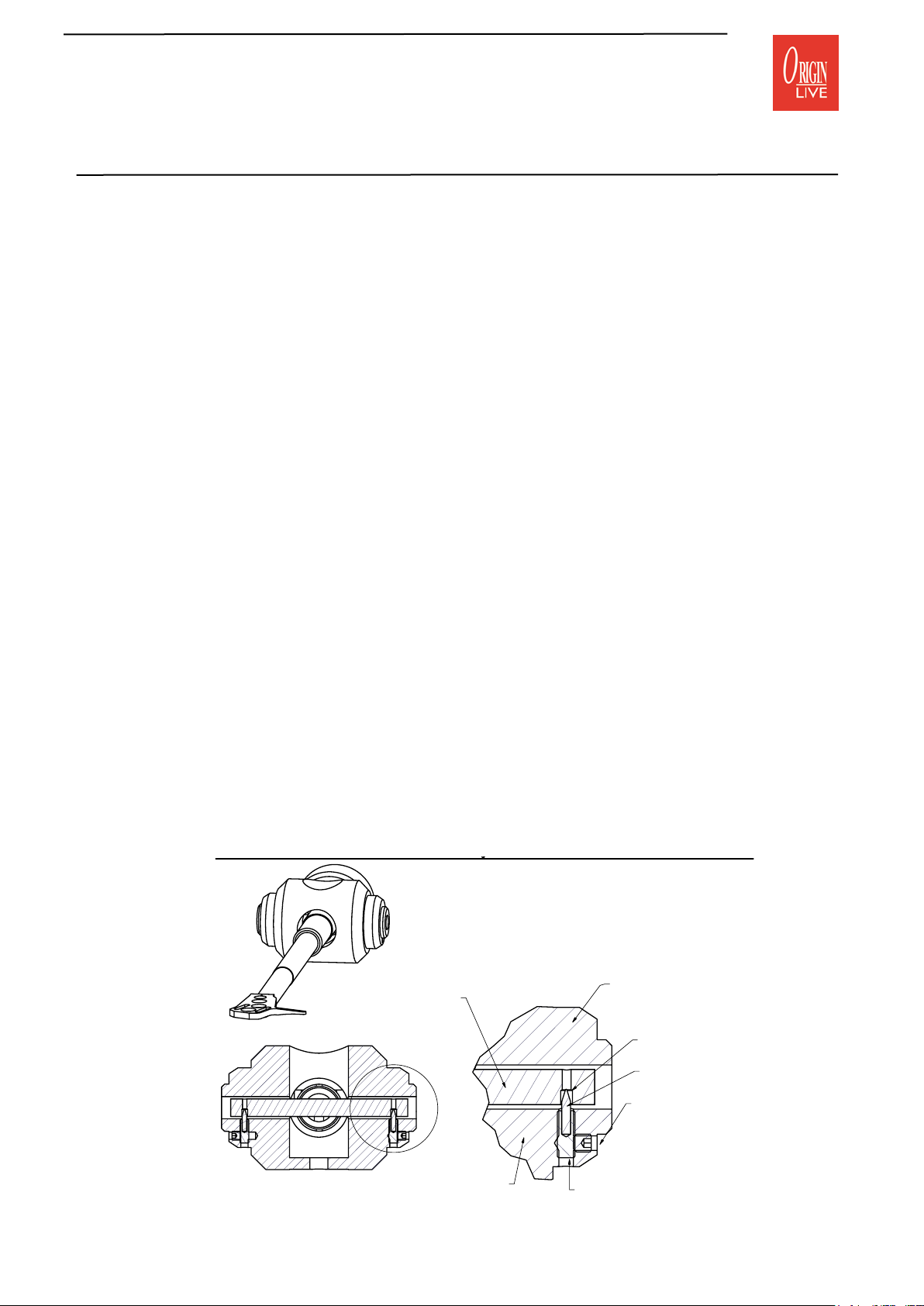
The below diagram showing an illustration of the dual pivot
bearing is shown to give an understanding of why the horizontal
axle is free to move a little in all directions except downwards.
This may be a little disconcerting until you become confident of
the inherent virtues delivered in performance. It is also reassuring
to know that the arm cannot be knocked off it’s bearings or
come loose in any way. You can turn the arm upside down and
nothing will fall off as it would in the case of a uni-pivot!
The pivot bearings are designed to reduce friction to the absolute
minimum practical level. In doing this there is a fine balance
to achieve both a long lasting, robust design and realizing the
potential of extremely low friction. In practice this means that
the arm must have a slight degree of movement due to a rounded
tungsten point in a shallow radiused (nearly flat) bearing cup.
The alternative to this is a very sharp, potentially fragile point
in a deep v shaped cup – this would certainly restrain the
movement of the point but would also increase friction.
The pivot points will “self centre” by sliding into the bottom
of the shallow low friction cup. However the final resting place
of the point in the cup may vary by 0.01mm or so. This would
not be noticed without the use of a very accurate digital stylus
force gauge – as the pivot position changes fractionally so can the
tracking force by up to plus or minus 0.05grams. In practice this
has no effect on performance and is also common among certain
unipivot designs with very low friction bearings.
A-A ( 1.50 : 1 )
CROSS SECTION OF ARM YOKE
PIVOT ARRANGEMENT FOR
CONQUEROR, ILLUSTRIOUS &
ENCOUNTER ARMS
(ignore differences in armtubes
and yoke shapes - these diagrams
show principles of operation
HORIZONTAL AXLE
fixed in arm
B
DETAIL INSIDE CIRCLE B
B ( 3 : 1 )
YOKE
SAPPHIRE CUP
for needle point
PIVOT NEEDLE
M3 AZIMUTH
CLAMPING
GRUB SCREW
Do not adjust
PIVOT HOLDER SCREW
do NOT adjust as you
this can only be factory set
Page 2

Making the dual points operational
The cork packing peices shown below are critical, to prevent damage to the
bearing points in transit. Gently remove these to make the arm operational
and keep the cork in a safe place. This MUST be replaced whenever you
send the arm by post or any form of courier as they throw boxes around
severely and damage to the points and cups occures unless the cork is in
place.
If you ever lose these instructions they can be downloaded from our web site under technical
support.
CORK PACKING PEICE
WEDGING ARM TUBE
TIGHTLY INTO TOP OF YOKE
AND TAPED ON
2 PEICES OF CORK PACKING EITHER
SIDE OF ARM TUBE AND THEN
WEDGED INTO THE YOKE HOLE TO
ENSURE THE ARM REMAINS CENTRAL
IN THE YOKE
CHECK THAT ALL IS WELL - Once you have installed the arm as per the general instruction
sheet, check the arm for accuracy - e stylus down force should be consistently accurate to
within plus or minus 0.1 grams. Higher deviations indicate that the bearing has been damaged or
incorrectly adjusted.
To check consistency measure the stylus down force over a succession of 10 or so movements of
the arm into the arm clip and then onto a stylus force gauge. It is best to use a digital force gauge
for this as a “balance” type can give inconsistent readings with errors of up to 0.5 grams.
Page 2
Page 3

VTA (vertical tracking angle) adjuster wheel
It is important to experimentally set the optimum arm height
by listening to different vta settings. If the arm base is too high
the sound is usually slightly on the bright side and lacking body
in the bass – too low and it veers on the dull side. To enable
precise and repeatable vta setting your origin Live arm has an
integral vta adjuster wheel. This method of height adjustment
is extremely accurate, with obvious benefits in terms of speed of
adjustment. This means better listening comparisons between
different vta settings.
VTA Calibration: The arm must be “unclamped” for the
vta wheel to work – see diagram for clamping grub screw
position. Just under the arm plate is the thin knurled vta height
adjuster wheel – The wheel has silver markings on the edge so
that you to see how far you turn it. There are actually only 2
silver marks to allow you to count each half revolution of the
wheel. Every half revolution is equivalent to a 0.5mm increase
in height. Rotating the wheel clockwise (looking down on the
wheel) raises the arm and lowering is the opposite.
Clamping: For the sake of speed in vta setting, we recommend
that you leave the arm unclamped during the comparisons.
However it will sound FAR better clamped tight, once you have
arrived at the vta “sweet spot”. An Allen key is provided for this
purpose and the position of the clamping grub screw is shown
in the relevant diagram.
The wheel is capable of raising the arm around 30mm but not
more than 20mm is recommended for optimum performance.
Thank you for purchasing an Origin Live arm. Enjoy getting
closer to the original sound and enter the heart of your music.
We hope to serve you in the future.
AZIMUTH CLAMPING SCREWS
(one on each side of yoke) Do not adjust
AZIMUTH PIVOT ADJUSTER SCREW
In underside of yoke - Factory set so do NOT
or your arm will cease to work properly
VTA HEIGHT ADJUSTER WHEEL
Half turn clockwise raises arm 0.5mm
Must slacken VTA clamping screw before turning
Reclamp after adjusting to your preferred tension
VTA CLAMP SCREW HERE
Tighten up hard once vta is set
Loosen when adjusting VTA
Do not adjust any other set screws on this level
COUNTERWEIGHT
CLAMPING SCREW
adjust
Do NOT adjust grub screw
on opposite side
of vta clamping screw
ENCOUNTER, ILLUSTRIOUS
& CONQUEROR
Page 3
Page 4

Repacking the arm for transit
e dual pivot bearing is a very precise and in some
ways delicate mechanism. Every care has been taken to
ensure that the arm reaches you in perfect condition
such that the bearings are accurate and very low in
friction. If you need to send the arm anywhere, the
following proceedure must be followed carefully.
Remove the counterweight and turn the vta adjuster
wheel up as high as possible (i.e anti-clockwise when
looking down on the arm ) - this enablles the arm to sit
in the box at the correct height.
Fit and nip tight the transit bolts and nylon
washers - the nylon washers are critical to avoid
damaging the paint. If you have carried this out
successfully the arm is clamped such that the end
caps are above the horizontal centre line of the
yoke.
Only now can you place the arm in the arm clip
and tape it down to the arm plate as shown on
page 3 - this operation must not be caried out
before inserting the transit bolts.
Pack the arm into it’s wooden box using the
foam packing peices
Pack the arm into it’s wooden box using the
foam packing peices.
CORK PACKING PEICES WEDGING
ARM TUBE TIGHTLY INTO TOP OF
YOKE AND TAPED ON - (use double
thickness of 1.5mm thick cork folded
over)
Origin Live Ltd, Unit 5, 362b Spring Road, Sholing, Southampton, SO19 2PB
www.originlive.com originlive@originlive.com
2 PEICES OF CORK PACKING EITHER
SIDE OF ARM TUBE AND THEN
WEDGED INTO THE YOKE HOLE TO
ENSURE THE ARM REMAINS CENTRAL
IN THE YOKE
Page 4
 Loading...