

Page 1

Dual pivot bearing design – why?
The Enterprise arm is a performance leader by virtue of it’s
innovative dual pivot bearing on the horizontal axle (which governs
the arms vertical movement). This design is similar in many
respects to uni-pivot designs – low friction and high decoupling
which give excellent defi nition and transparency. However
uni-pivots can be fi ddly to set up and because of their relative
instability exhibit a mediocre bass performance. Dual pivot design
has all the advantages of uni-pivots but none of the drawbacks.
Vertical movement of the arm is handled by the dual pivot and
horizontal movement by our usual highly specifi ed conventional
bearings.
Handles like a conventional gimballed
arms
You should handle the arm in exactly the same way as a
conventional gimballed arm. In other words you do not need
to worry about setting up azimuth and balancing the arm. The
azimuth has already been set, such that the headshell is parallel to
the arm mounting surface. We strongly recommend that you never
adjust the factory setting even though it is possible via the pivot
screws. Correct azimuth setting is tricky at the best of times and
unless an extremely careful record is kept on the original factory
settings the arm will probably end up not working correctly. If
in trouble see technical support on our web site www.originlive.
com/troubleshooting_tonearms.htm
Having said this it is recommended to slacken off the azimuth
clamping screws NOT the azimuth adjuster screws. Slackening
the clamping screws has the effect of increasing the performance
signifi cantly.
The below illustration shows the dual pivot bearing to give an
way. You can turn the arm upside down and
The pivot bearings are designed to reduce
would certainly restrain the movement of the point but would also
The pivot points will “self centre” by sliding into the bottom
with very low friction bearings.
(
)
PIVOT POINT IN THREADED SCREW
Adjusts azimuth
YOKE RIGIDLY FIXED TO ARM TUBE
TURRET PLATE
- rotates freely on conventional bearings
ENTERPRISE FRONT VIEW OF DUAL
PIVOT ARRANGEMENT
SIDE VIEW OF DUAL PIVOT
ALLEN SCREW HOLDING PIVOT POINT
rotating clockwise raises this side of the yoke.
Movement
NOTE
It is not nessecary to understand
these diagrams but they are
included for information only
SAPPHIRE CUP BEARING
When arm is horizontal - bottom surface
of the yoke should be roughly parrallel
with turret plate in side view.
This is set at factory and only held by
friction fit which can be forced out of
alignment by mishandling or transit.
Cork strips are inserted to prevent
movement occuring in transit.
Page 2
wheel
VTA Calibration:
The arm must be “unclamped” for the
vta wheel to work – see diagram for clamping grub screw
For the sake of speed in vta setting, we
The wheel is capable of raising the arm around 30mm but not
Transit and unpacking:
You will notice 2 cork strip
wedges in the space between the top of the arm tube and the
yoke. This is to prevent any movement out of parallel between
Thank you for purchasing an Origin Live arm. Enjoy getting
We hope to serve you in the future.
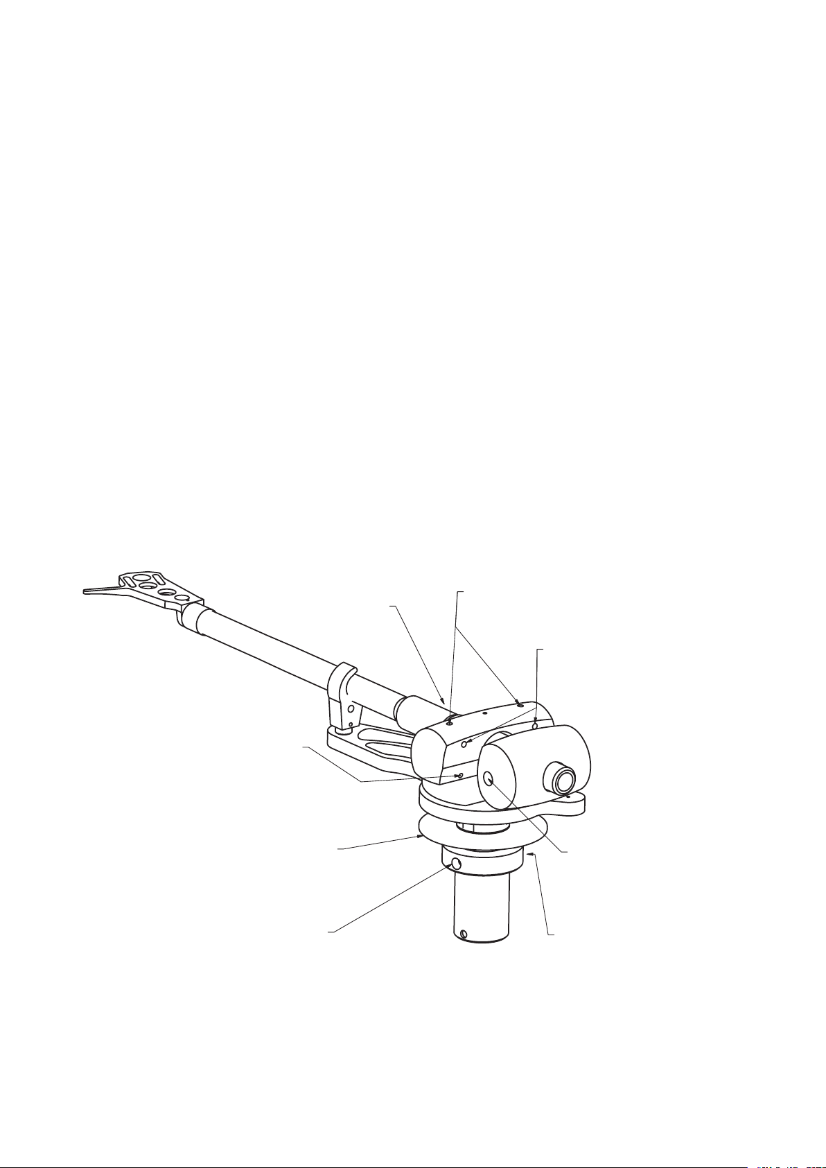
VTA CLAMPING SCREW
Tighten according to suit your deck
(Advise light clamping or none at all)
AZIMUTH PIVOT ADJUSTER SCREW
(Do
NOT adjust without reading instructions- in
worst case you could damage pivots if you do)
COUNTERWEIGHT
CLAMPING SCREW
line up with groove along stub
DO NOT TOUCH THESE SCREWS
they clamp in the retaining rings which
prevent the arm coming apart
- loosing can result in breaking arm wires.
ENTEPRISE ADJUSTMENTS
VTA HEIGHT ADJUSTER WHEEL
Half turn clockwise raises arm 0.5mm
Must slacken VTA clamping screw before turning
Reclamp after adjusting to your preferred tension
AZIMUTH CLAMPING SCREWS
Best to slacken off approx 1 turn
for optimum performance
Tighten for transit
Do NOT adjust this grub screw
opposite the VTA clamp screw
Remove cork packing
strips and keep them
for transit purposes
Page 3

e 2 pivot points are factory set so that they are exactly
words the points are clear of the jewelled cups in transit.
To lower the points into the cups so that the arm can
Turn the 2 azimuth pivot adjuster screws exactly 4 turns
yoke). To ensure 4 exact turns simply insert the allen key
wind the 4 turns till the handle ends up in the same
WARNING - do not wind further than 4 turns or to a
e bearing operation and well being should be checked
Setting up from new
Azimuth clamping screws
Azimuth clamping screws
Turn the 2 azimuth pivot adjuster screws exactly 4
Page 4

to ensure the
Next wind in each adjuster screw (clockwise)
just
just
starts to lift the
yoke off the turrret plate. is is what will be
yoke.
ere are two methods of achieving this
will be relatively free but when it meets the
jewelled cup and starts lifting the yoke against
where resistance
is the ground datum.
Azimuth clamping screws
Azimuth clamping screws
photo of “gap”
YOKE
YOKE & TURRENT
TURRET PLATE
AND TURRET PLATE
SUMMARY OF PROCEEDURE
e headshell is
yoke in terms of rotation (azimuth). We therefore use the
yoke is level then we know the headshell azimuth is correct
e aim of the adjustment described below is to end up
with the
directly
A summary of the proceedure described below is fi rstly to
Page 5

yoke lift off the turret plate.
e second way of adjusting to ground datum AND
Adjust the screw anticlockwise very slightly so that when
just
just
clear of the turret plate by
A fi nal check is to confi rm that you can just insert the
yoke - the cork strip should be between the protrusion
WARNING - do not wind to a point where you meet
To check consistency, measure the stylus down force over a succession of 10 or so movements
ank you for purchasing an Origin Live arm. Enjoy getting closer to the original sound and
Page 6

e dual pivot bearing is a very precise and in
Tighten the azimuth clamping screws lightly onto
Tightly tape the arm tube to the arm rest plate
www.originlive.com originlive@originlive.com
 Loading...