

Page 1
Assembly of deck sub-chassis to plinth
Read carefully or damage can occur
Please fit the Subchassis to the plinth following the instructions on these sheets. This part
is not pre-assembled to prevent potential distortion that can occur in transit if it is rigidly
attached to the plinth.
Preliminary notes The subchassis is carefully built such that the platter is parallel to the
armboard. Do not tamper with any of the bolts on the sub-chassis even if they may not
appear to be seriously tight.
On the Resolution and Sovereign decks - When you finally level the deck, note that the
acrylic part of the armboard is not a reference surface – only the chrome inner disc is true
to the platter level.
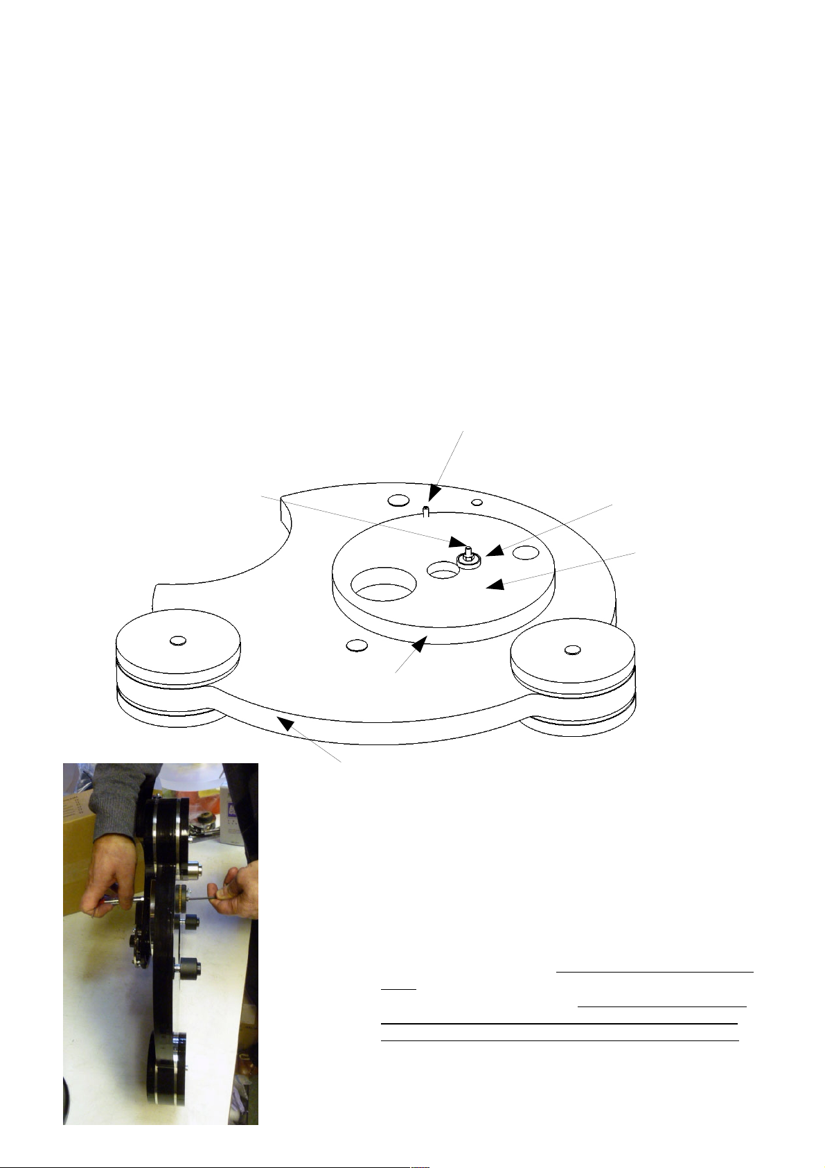
Anti-rotate stud - do not
Turntable as packed / on arrival
Adjust or remove
Pivot bolt – cap head
On TOP
Pivot Spacer
Pivot nut hidden
From view UNDER
plinth
Inertia disc
Plinth
The deck arrives as shown above. First, undo the
Pivot nut using the spanner provided whilst holding
the bolt head on top with the Allen key. It is easiest to
rest the deck on it's side (see photo alongside) whilst
you carry out this operation.
Once the nut is removed, do not allow everything to fall
apart. Hold the pivot bolt in, and keep the inertia disc
pressed onto the plinth. Also check that the anti-rotate
stud in the underside of the inertia disc remains in its
restraining hole in the plinth (see illustration overleaf)
Page 2
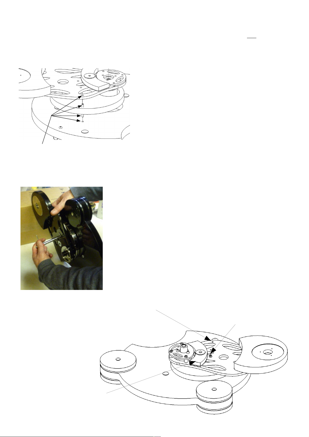
EXPLODED VIEW OF ASSEMBLY
Still holding the deck on it's side, ensure that the pivot
spacer (see Fig 1 illustration) is in position and and then
place the sub-chassis over the pivot bolt and ant-rotate
stud. The sub-chassis has 2 small holes that locate
precisely over the aforementioned bolt and stud so
ensure these are both penetrated.
Only the pivot bolt needs to be tightened, by fitting the
pivot nut on top of the sub-chassis. Tighten the pivot nut
firmly. If you only have a pair of pliers this is best carried
out using a 3mm Allen key applied to the bolt head.
Ensure the anti-rotate stud stays located in the subchassis while you tighten the nut and once tightened
ensure that you can see the anti-rotate stud is located in
the subchassis hole. This is CRITICAL or the sub-chassis
will not be level with the inertia disc and performance will
be severely affected. If all is finished correctly then the
sub-chassis should be free to rotate almost imperceptibly
in the horizontal plane.
Top & bottom anti-rotate
bolts must locate in hole
in plinth AND hole in subchassis as shown
NOTES If the assembly comes apart before you get to
tighten the nut then the exploded diagram below shows
how to re-assemble everything. It is best not to allow this
to happen in the first place.
If you need to send the deck by carrier then remove the
sub-chassis and pack according to packing instructions –
remember to tighten the inertial disc onto the plinth using
the pivot nut.
You are now ready to move on to the owner manual for
final set up.
Placing spanner over pivot nut
for final tightening
Anti rotate Stud located in Sub-chassis hole
Note: On the Calypso the curved damper
is on the underside of the sub-chassis &
The armboard is not as shown here.
Pivot bolt tightened firmly
Page 3

Anti-rotate stud
Pivot nut
Pivot spacer
Inertia disc
Cork washer glued to top of pivot lower disc
Pivot lower disc
Pivot bolt
 Loading...