

Origin live AURORA GOLD Owner's Manual
Page 1
O R I G I N L I V E
A U R O R A G O L D T U R N T A B L E
O W N E R S M A N U A L
Read carefully and do not tighten bolts you may think are loose
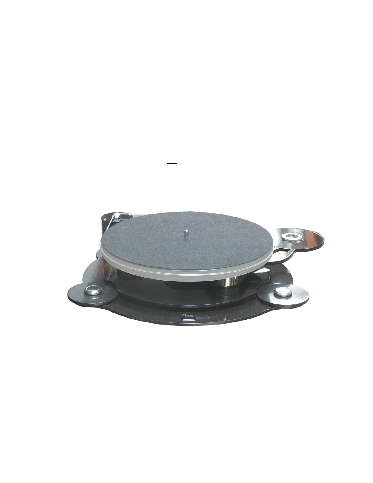
Latest version of Aurora Gold turntable - shown with Origin Live upgrade mat which can be ordered
as an optional extra to upgrade the deck
Use belt on lower groove of pulley

Page 2
Contents
I N T R O D U C T I O N ( R E A D
C A R E F U L L Y )
Congratulations on choosing your Origin Live turntable. You
now have one of the finest sounding turntables available – not
only will it provide an extraordinary level of performance but
also reliability and low maintenance.
This manual covers variations of the Aurora Gold produced
over the years and so some photos are only representative.
The portions of the instructions printed in light grey are
optional reading for more in depth knowledge if necessary. It
is critical that the remainder of the instructions are read fully
to achieve the full performance from your turntable. There are
aspects of the deck that run contrary to what you may expect,
so before altering anything it is important to have fully read
the manual or degradation will result.
The Aurora Gold turntable is simple to set up. If you have
a problem please refer to the instructions. If your problem
persists you should speak to your dealer or have a look at the
Origin Live web site www.originlive.com under “general
information” then “technical support” from the drop down list.
The instructions are written for owners with no previous
experience of turntables. Some sections may therefore appear
lengthy, as they need to cater for all potential questions. When
reading the instructions refer to the various diagrams for part
names and clarity.
The deck can take approximately 15 minutes to set up
depending on your expertise. The dc regulator electronics may
initially encounter speed drift when first started (if they have
not been run in) and may need at least 4 hours to run in before
the speed can finally be set with accuracy.
We wish you an increased musical experience with your Aurora
Gold turntable.
Parts list
Plinth
Turntable bag
o Belt
o 1 large & 1 small cable clip and attachment
nylock nut and M4 x 16 bolt (usually on
deck)
o Oil Bottle
o 3mm Allen key & 2.5 mm Allen key
o 3 cork discs for levelling if necessary
o Cork ring for arm
o Threaded VAT adjuster
o 4mm spacer for 3 point mounting
Platter
Sub-chassis
Motor pod
Control box
Transformer for 230 volt or 110 volt mains supply
Arm (optional), alignment gauge, but no arm instruction
sheets as included in deck instructions
P A P E R W O R K
Turntable instructions & Strobe card
Page 3
Turntable set up
When you unpack the deck, check that you have all the items listed in the
parts list.
S E T T I N G U P T H E P L I N T H
Place the motor pod in position at the rear of the plinth. The motor pod
should be located approx 2mm away from the edge of the plinth outer ring.
Place the sub-chassis on the plinth as shown in the photo. The small
locating pins on the underside of the two black pods locate in the small holes
on the plinth. DO NOT TIGHTEN THE BOLTS IN THE PODS - they
are set to be loose deliberately - if they are tightened sound degradation will
result.
You will find that the sub-chassis can rotate very slightly on the plinth – rotate
it so that the bearing moves towards the motor pod.
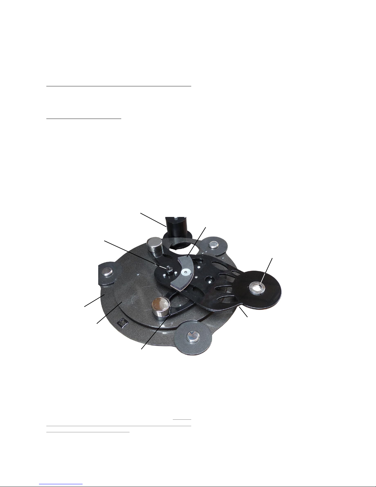
Photo showing sub-chassis & part names
VTA threaded height adjuster use on arms with threaded base
- turn clockwise to raise the arm
SUB-CHASSIS placed on plinth such that pod pins
locate in plinth holes
MOTOR POD placed approx so
that a gap of approx 2mm exists
between pod tube and edge of
plinth outer ring
CURVED DAMPER
SUB-CHASSIS PLATE
BOTTOM SUB-CHASSIS PLATE
BEARING HOUSE
PLINTH OUTER RING
PLINTH INNER PLATE
NOTES:
Trouble shooting notes on the sub-chassis (optional reading)
1. The sub-chassis is attached to the “bottom sub-chassis platee” by one “pivot
bolt” – the two plates should be free to swivel and are loosely restrained by an
“anti-rotate bolt” – this locating bolt on the side of the sub-chassis should be
left alone. The pivot bolt is tightened at factory and should not be tightened
or the performance will degrade significantly.
2. If this setting is lost for any reason then the correct tension is such that
the bottom sub-chassis plate can rotate minutely but freely in relation to the
subchassis plate but has minimal “rocking” motion in the vertical plane.
3. The “anti rotate” bolt is bolted tightly to the bottom sub-chassis plate but
has minimal contact with the sub-chassis.
4. If for any reason, tension is lost on any of the other bolts then they should
be just “nipped” tight by 1/8 of a turn from the point where you can just turn
the bolt & nut freely in it’s hole – any tighter than this and performance is
degraded.
Page 4
F I T T H E T O N E A R M
Mounting Origin Live arms
Thread the threaded vta adjuster onto your arm if it is an Origin Live
Encounter or above. If your deck is a Sovereign and you have an Encounter
arm or above - do not fit the threaded vta adjuster ( the exception to this
rule is when the Sovereign uses the heavyweight platter which should use
the threaded vta adjuster). The adjuster must be oriented such that the
largest diameter is uppermost. Insert your tonearm into the armboard hole
such that the vta adjuster locates centrally. Next fit the cork washer as shown
in the diagram below before threading on the large clamping nut. You can
set the arm to the correct height later but for now just clamp the arm in
position using the large nut. To adjust the height of the arm, screw the vta
adjuster up or down and reclamp the arm using the large base clamping
nut.
NOTE - For Origin Live arms with integral vta adjuster i.e Encounter
and above you should raise the arm height to just below the right level
using the threaded vta adjuster and then use the arm vta wheel for fine
adjustment.
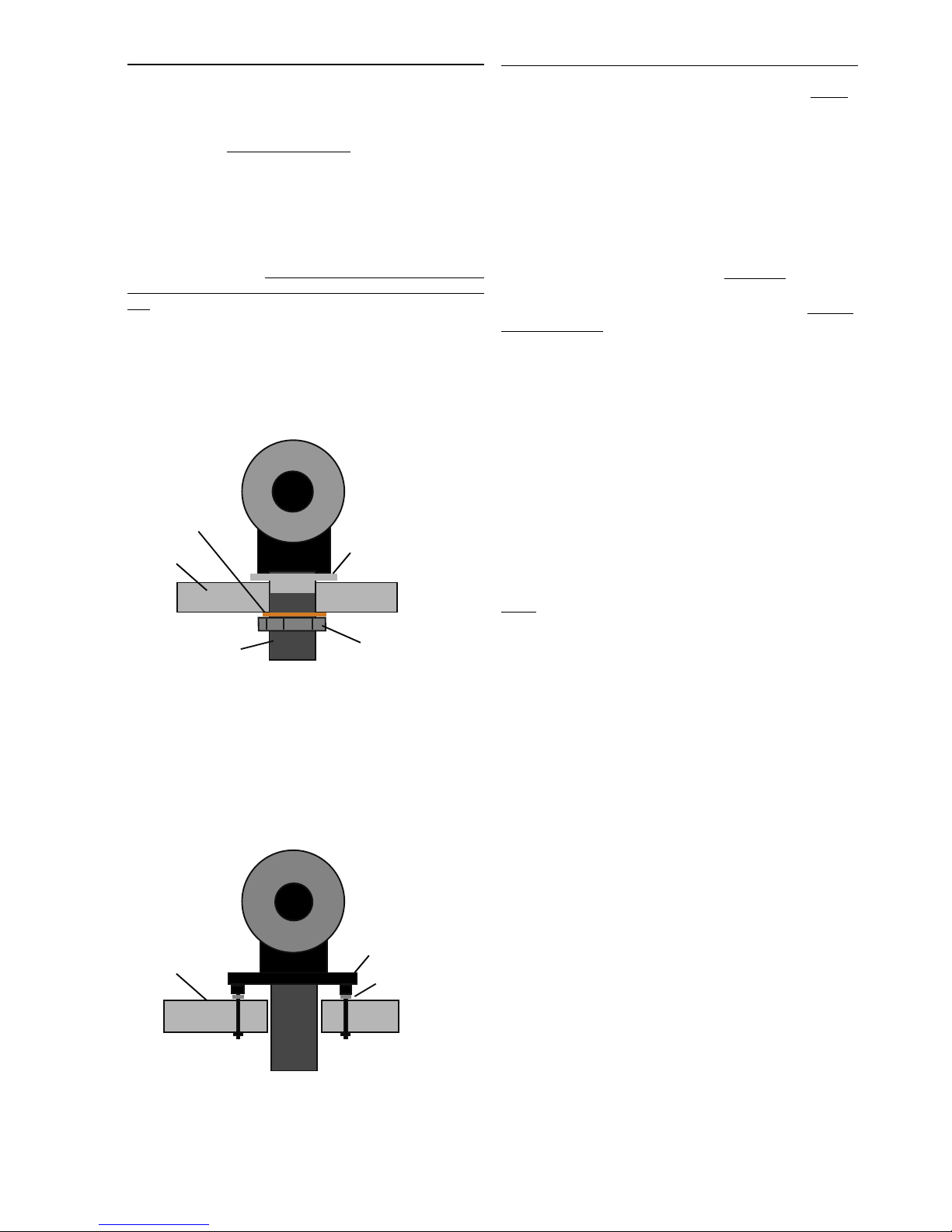
A R M
REAR VIEW OF ARM ON ORIGIN LIVE DECK WITH
THREADED VTA AND CORK WASHER
ARM MOUNT
SURFACE
CORK WASHER
LARGE CLAMPING NUT
THREADED ARM BASE
THREADED
VTA ADJUSTER
If you have the OL1 or Rega arm with 3 hole
mounting
The arm is bolted or screwed to the deck using the 3 mounting holes in the
base of the arm. To raise the arm for VTA adjustment you will need to fit
3 or more spacing washers under the arm base holes. One peice spacers are
available from Rega if you want a neater looking solution.
3 POINT ARM MOUNTING
Sub-chassis or
armboard
3 off bolts or
wood screws
Spacers
For other makes of tonearm
Origin Live can provide the correct cut out in the sub-chassis or armboard
for other makes of arm and after this refer to your arm installation
instructions.
F I T T H E P L A T T E R
NOTE - On newer decks (April 2009 onwards) the platter is a “loose” fit
over a metal bush on the spindle. This means the platter can be removed
from the spindle. TIP - Once the platter is fitted over the bush it pays to
spin it slowly by hand while holding the top of the spindle stationary with
your other hand - this helps the platter to “bed down” onto the bush and
become more level.
Oil the bearing - with the small oil bottle supplied, run approx 10 drops of
oil into the top of the bearing house.
Insert the spindle - Wipe the platter spindle surface first
to ensure that it is absolutely clean and very gently insert it
into the bearing house (If the oil does not overflow when the
spindle touches the bottom then try 2 drops at a time till you
achieve overflow - wipe away excess oil without withdrawing
the spindle. Ideally you should spin the spindle slowly as it
settles into the bearing to ensure distribution of oil.
When you oil the bearing you can get a false impression of
overflow if the spindle has oil on it - the oil simply scrapes off
as the bearing goes in and ends up on the top of the bearing
house. You can “feel” overflow when inserting the spindle, it
meets resistance at the bottom which is not a “thud” of the
spindle hitting the bottom but rather a build up of pressure
of the bearing landing on a bed of oil. By further pressing,
you can then see the oil being squeezed out at the top. Lastly,
if applicable, carefully lower the platter over the spindle till it
rests on the lower flange of the platter bush (ensure mating
surfaces are clean).
gently insert the platter spindle into the bearing house (If the
oil does not overflow when the spindle touches the bottom
then try 2 drops at a time till you just achieve overflow - wipe
away
N O T E :
The bearing needs a few minutes to “run in” and should run
silent when truly vertical and full of oil - if it doesn’t do so,
there has probably been contamination with dust and you
will need to clean it out with a lint free paper towel or similar
wrapped around a thin rod. If you do this, be sure to also wipe
the oil off the spindle as this also may contain microscopic
contamination that is not visible.
Fit the belt over the motor pulley and platter.
Set the belt tension by positioning the motor housing relative to the
turntable. Ideally the centre of the pulley should be approximately 225mm
from the centre of the bearing house.
Note: It is very common for people to set the belt tension too
tight, which can slightly degrade performance. The optimum
setting is where there is enough tension to turn the platter
without audible wow and flutter but no more. This may take
some experimentation.
It also aids performance to clean all the running surfaces with
mentholated or surgical spirit.
Ensure that the motor pod is not touching any other plates on
the deck.
 Loading...