

Page 1
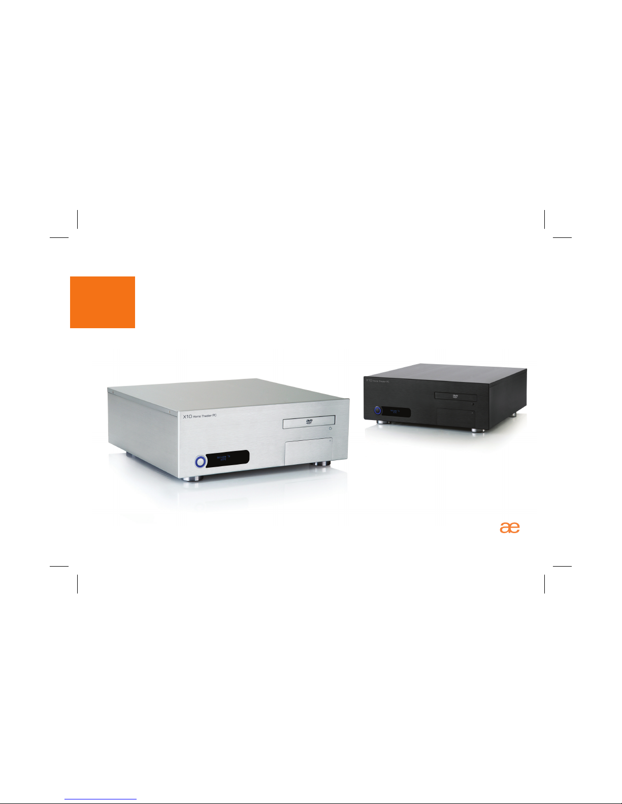
Origen
X10
user guide
Page 2

Page 3

X10
user guide
Thank you for purchasing this OrigenAE HTPC enclosure.
Please read thoroughly before installation.
OrigenAE is not responsible for any damages
due to external causes, including but not limited
to, improper use, problems with electrical
power, accident, neglect, alteration, repair,
improper installation or improper testing.
Revision X10.V2.11/06
Copyright © 2007 OrigenAE Technology.
All rights reserved
Page 4

index
X10 overview
Opening the case
PSU and drive installation
VFD/IR cable diagram
VFD/IR module installation
oftware installation
Installing VFD/IR driver
Installing VFD/IR software
Removing drive cage
Removing PSU bracket
Optical drive bezel installation
Front ports cable diagram
S
-5
6
7
8
9
10
11
12
13
14
-
-6
-6
-
-
-
-
-
-
-
-
Page 5
2
3
4
7
9
10
11
12
5
6
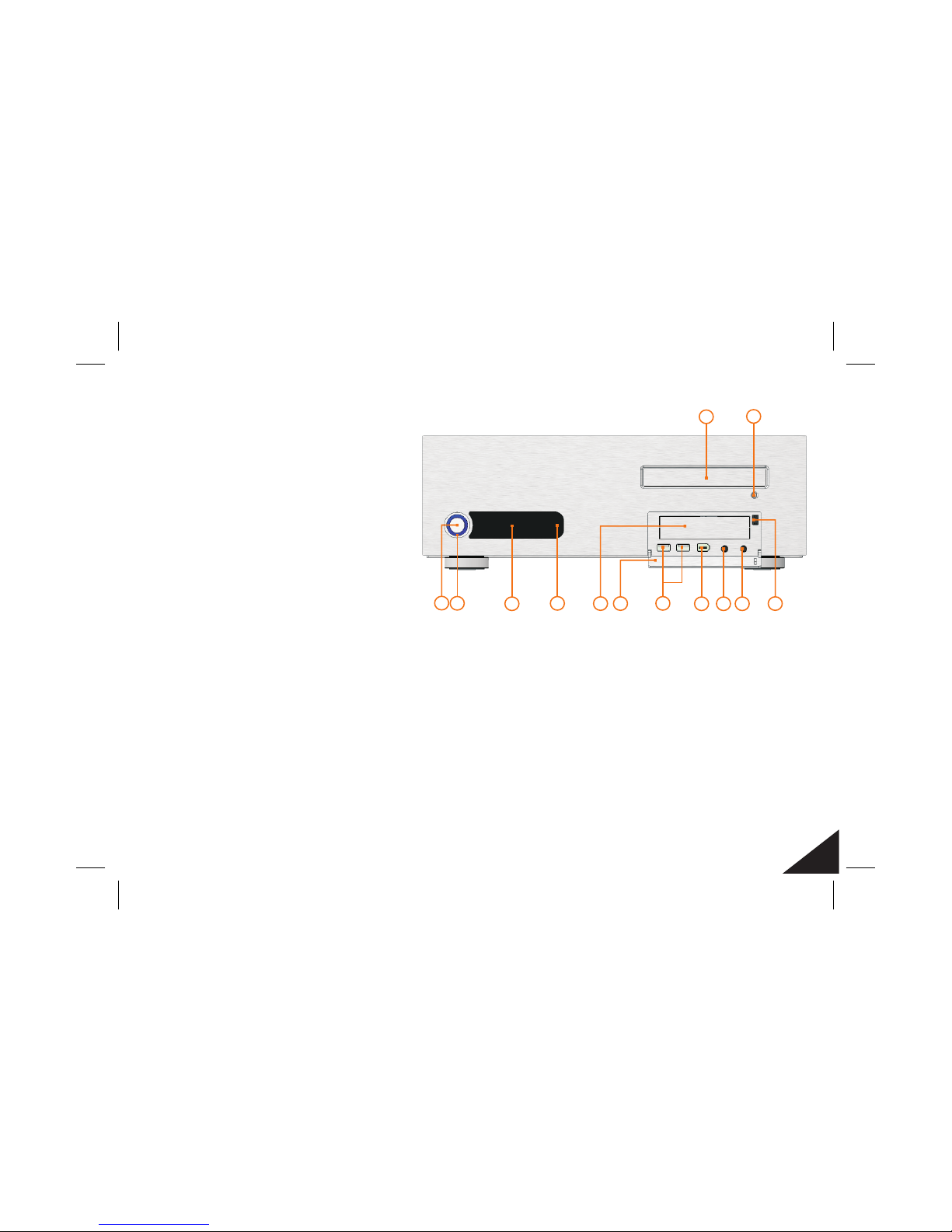
HTPC power button
HTPC power LED
IR receiver (behind acryl)
[bezel]
”
VFD display
Optical disk drive
Optical disk drive eject button
3.5 bay
I/O port bay cover
USB ports
1394 port
Microphone socket
Headphone socket
Bay cover latch
12345678-
910 11 12 13 -
X10 overview.
Front view highlighting
features and controls.
5
External dimensions (WxHxD)
Motherboard support
Drive bays
PSU support
PCI / AGP card support
Front I/O ports
Net weight
VFD specification
435x150x460mm
ATX
1 x 3.5” internal,
1x3.5”+1x5.25” external
ATX
Full size
2 x usb ports, 1 x 1394 port
1 x microphone, 1 x headphone
4.5kg (approx)
169x39x32mm
2 [lines] x 16 characters
blue colour
1
8 13
X10 overview
Page 6

Removing drive cage & PSU bracket.
This will need to be done before the
drives and PSU can be installed and
is achieved by removing the screws
as indicated in the diagram.
Opening the case.
To remove the lid of the case,
undo the 4 screws indicated.
Opening the case / Removing drive cage & PSU bracket
6
Page 7

3.5 media drive (optional)”
Drive installation procedure.
The X10 supports 1 x hard drive,
1 x optical drive and 1 x 3.5” drive.
The 3.5” bay can be used for a
media drive or any other size device.
Be sure to use the correct screws
for each type of drive installed.
Ensure the hard drive screws
are secured as far back on the drive
brackets as possible, for correct
chassis alignment (see inset).
Power supply & drive installation
1
3
2
7
Optical disk drive
Hard drive
Power supply installation procedure.
After removing the PSU bracket, as shown on the previous page,
you will need to screw it to the power supply unit as shown (1).
Then, connect the internal power cable (2) and ensure the PSU
power switch is ‘ON’. Finally the PSU can be secured by hooking
the bottom of the bracket as shown (3) and screwing in place.
Page 8

Optical disk drive bezel installation.
The X10 is supplied with an aluminum optical drive bezel to match the finish of the case.
The installation procedure requires that the plastic drive bezel that comes fitted on your
drive be removed and replaced with the aluminum X10 drive bezel.
Remove the existing plastic drive bezel from
your optical disk drive. This is normally done
by uncliping it and sliding it upwards. The
drive door should be ejected when doing
this to gain access to the bezel. It will also
assist to have it ejected when fitting the
replacement aluminum bezel.
Once the original bezel is
removed, peel the protective
layer away from the double
sided foam on the reverse of
the aluminum bezel. Carefully
align and stick the new bezel
onto the optical drive tray.
Optical drive bezel installation
8
Page 9
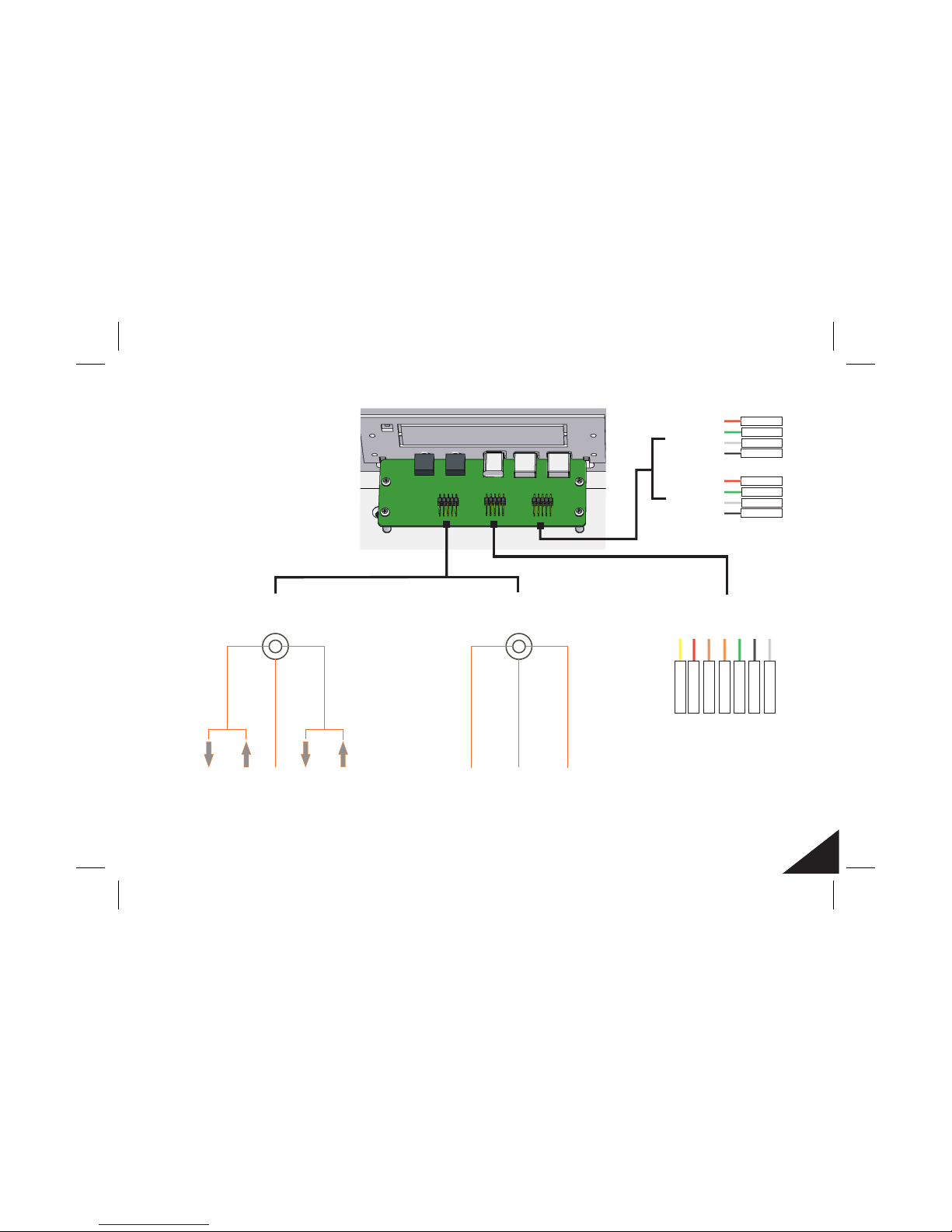
Front ports cable diagram.
The X10 provides front audio,
USB, and 1394 for
motherboards that support
these . There
are 3 cables that can be
connected to the internal
headers of your motherboard.
ports
connections
LEFT
RIGHT
GROUND
R-OUT
NEXT-R / RET-R
L-OUT
NEXT-L / RET-L
GROUND
LEFT
RIGHT
GROUND
MIC-VCC / PWR
MIC-IN
GROUND
Headphone
Microphone
IEEE1394
TPB+
VCC
TPA-
GND
SH-GND
TPA+
TPB-
USB1
USB2
GROUND 1
DATA- 1
VCC 1
DATA+ 1
GROUND 2
DATA- 2
VCC 2
DATA+ 2
Front ports cable diagram
9
Page 10
1
2
3
4 65 7
108
11
12 1413
9
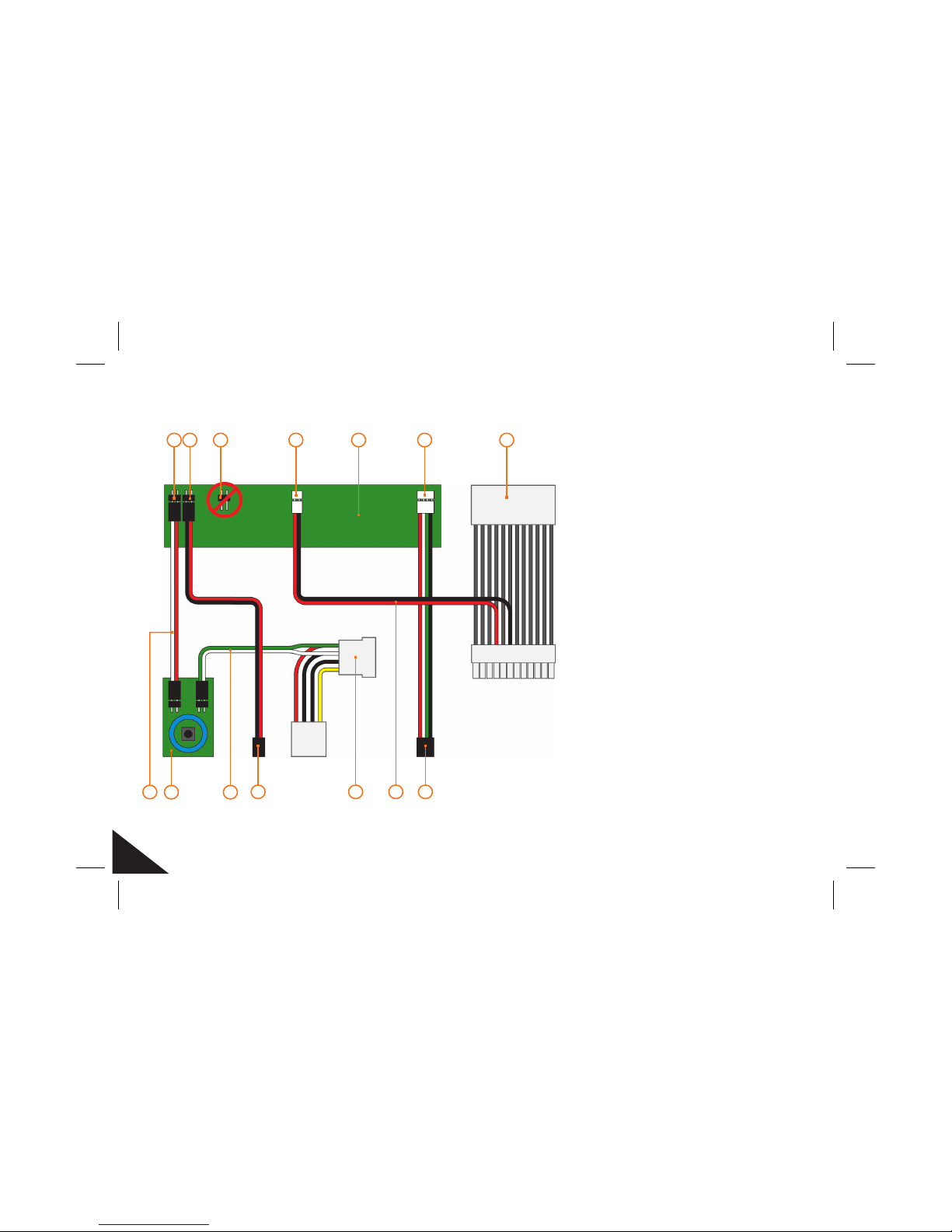
Power switch IN
Power switch OUT
Programming pin (do not use)
+5V standby
VFD PCB
USB connector
Standby ATX power cable
Power switch cable
Power switch/LED PCB
LED power cable
Switch cable (to )
Molex power connecter
VFD standby power cable
USB cable (to )
motherboard
motherboard
12345678-
910 11 12 13 14 -
VFD/IR cable diagram.
This is a general overview of
the cable layout connecting
the VFD/IR module, power
switch (power button) and
the . Please refer
to your manual
for the location of the correct
ports and header pins.
motherboard
motherboard
VFD/IR cable diagram
10
Page 11
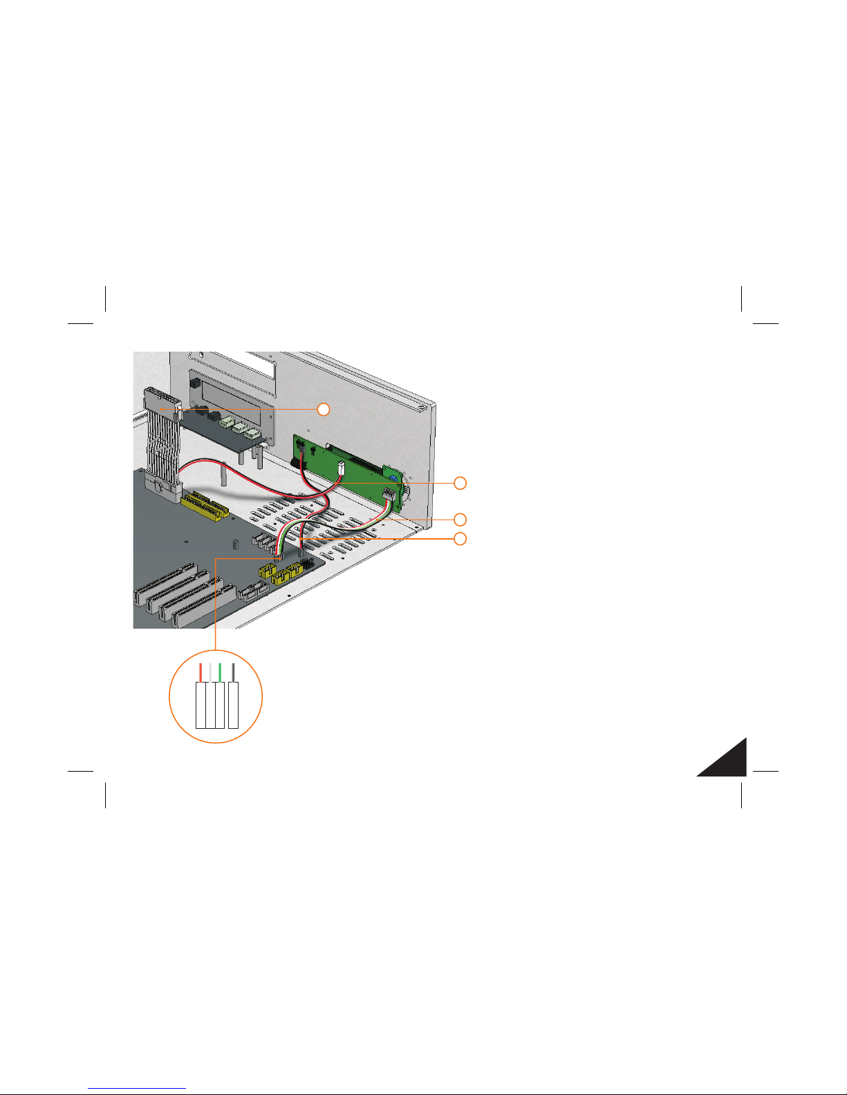
VFD/IR module
installation procedure.
This should be done
once the motherboard
has been fitted, and
before the power supply
has been installed.
Standby ATX power cable.
VFD/IR standby power cable.
VFD/IR module USB connector.
Switch cable motherboard connector.
This cable is required to draw a standby
current from the PSU when the PC is off. This allows the IR module
to function when the power is off, and turn the PC on remotely.
This is the internal USB header cable
that connects the IR module to a free internal USB header. It allows
the IR Trans software to communicate with the IR module.
This cable connects the
motherboard power on header to the IR module for manual
and remote power on functions.
1-
2-
3-
4-
3
1
4
2
D+
VCC+
D-
GND
VFD/IR module installation
11
Page 12
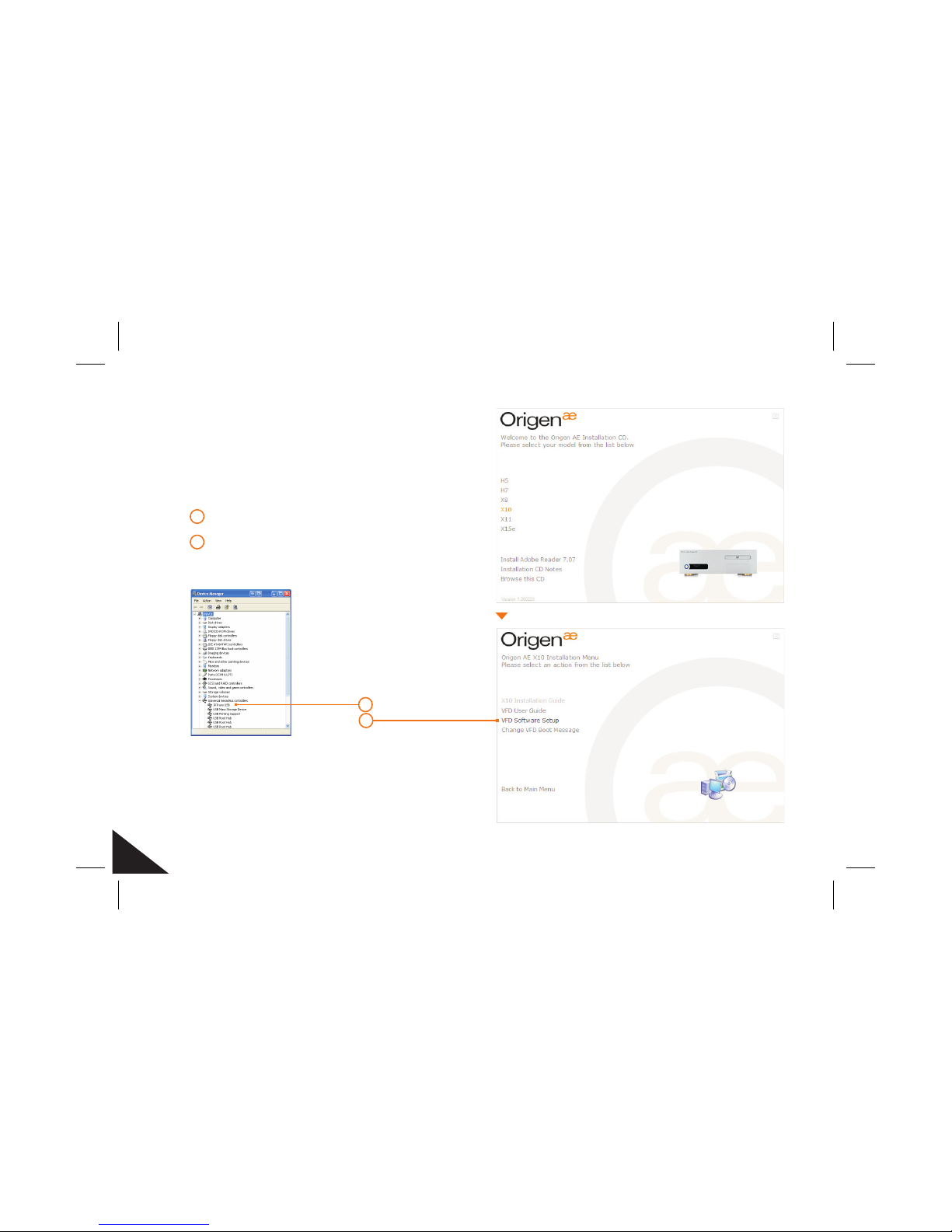
2
VFD/IR Software Installation.
There are 2 steps required to install the
necessary software to operate the VFD/IR:
1 VFD/IR module driver installation
2 VFD/IR module software installation
You will require the CD provided to begin
the installation of the VFD/IR software,
and you should select the X10 option
from the main menu to begin.
1
oftware installationS
12
Page 13
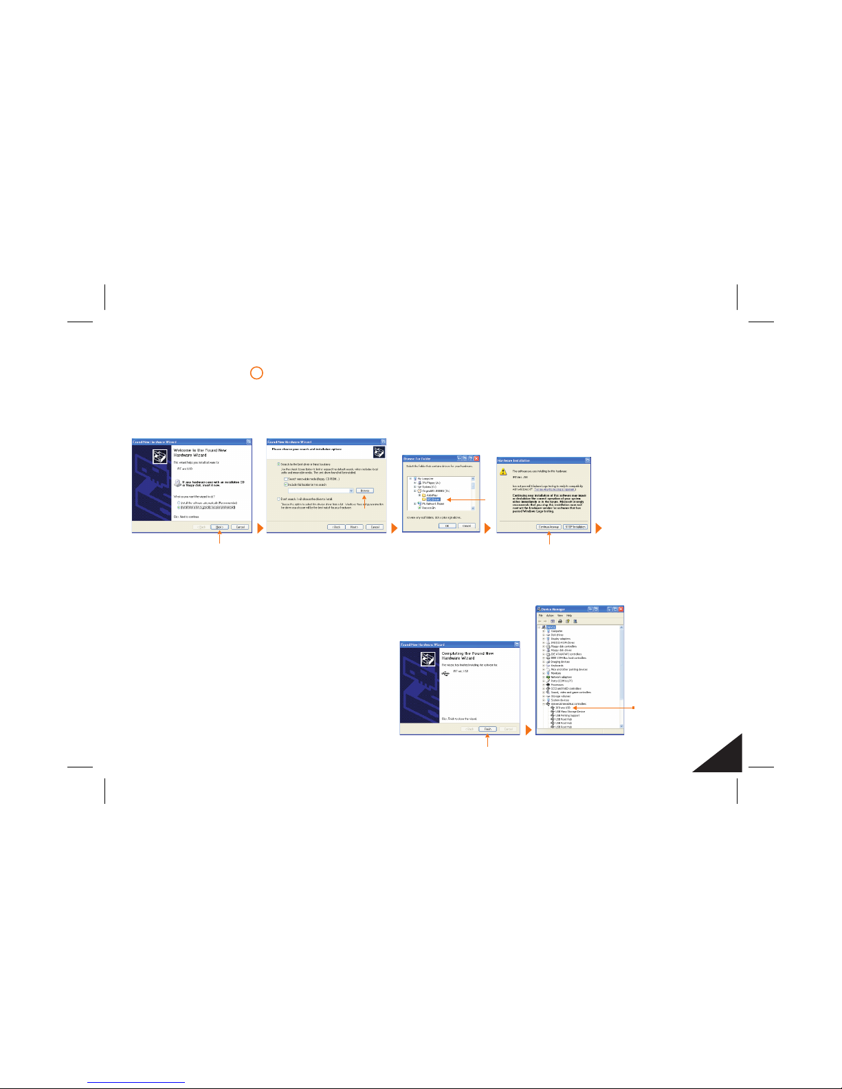
Installing VFD/IR driver.
Prior to running the VFD/IR software, the driver must be installed.
This is done by following the procedure below.
1
Browse to your ROM DRIVE and select the folder ‘VFD
Driver’, then Click ‘OK’. When returned to the previous
dialogue box click ‘Next’. Check the cable connection.
When the VFD/IR
module is connected
for the first time, the
’Found New Hardware
Wizard’ will start.
Alternatively, goto the
device manager, select
IRTrans USB and
reinstall the driver.
Make sure ‘Search for
the best driver in these
locations’ and ‘Include
this location in the
search’ are selected.
Click ‘Browse’.
You can verify
that the VFD/IR
driver has
been installed
correctly by
checking in the
device manager.
Installing VFD/IR driver
13
Page 14
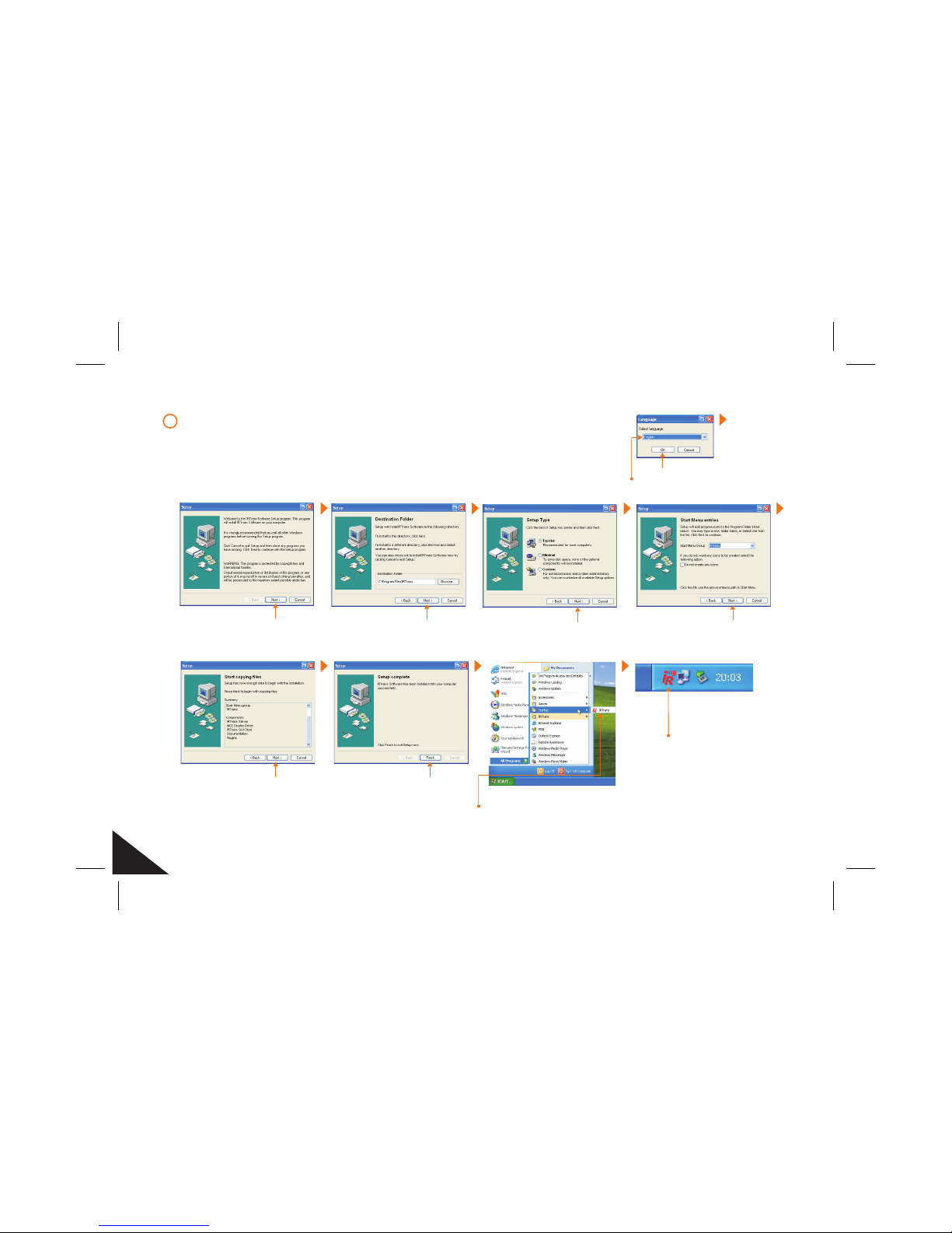
Installing VFD/IR Software.
The software installation is started by clicking the link shown on the
Installation CD. Follow the steps below to complete the installation.
2
Installing Software
Select language.
Software will create an
entry in the startup directory
and will automatically start
on new reboot.
When the IR software
is running, this icon
will be displayed
in the taskbar.
Installing VFD/IR software
14
Page 15

notes
Page 16

#209 Baeksan B/D
763-2 Hengsin-Dong
Dukyang-Gu
Goyang City
Gyounggi-Do
412-220 South Korea
e-mail:[email protected]
Contact Details
Global Product Support
Website
www.origenae.com
Origen
 Loading...