

Page 1

M10 user guide
Origen
Page 2

M10 user guide
ae
Thank you for purchasing this Origen htpc enclosure. We recommend
that you read this user guide thoroughly before installation.
ae
Origen has rapidly grown to be one of the worlds leading HTPC enclosure
manufacturers since its inception in 2000. We were one of the first companies
with the vision to produce high end htpc enclosures that harmonise with
mainstream audio visual equipment, allowing the pc to leave the office
and fit effortlessly into the living room environment.
We are driven by the passion to produce exceptional products
that push technical and aesthetic boundaries to new levels.
For more information on all of our products,
visit www.origenae.com
ae
Origen is not responsible for any damages due
to external causes, including but not limited to,
improper use, problems with electrical power,
accident, neglect, alteration, repair, improper
installation or improper testing.
ae
Copyright © 2009 Technology
Origen
All rights reserved
Page 3

index
M10
M10 overview / Accessories
Opening the case
Optical disk drive installation
Hard drive installation
Mainboard installation
Max height CPU cooler
VF310 cable reference diagram
Installing VFD/IR Software
Adapter connecting / Specification
4
5
5
6
6
6
7
8
9
Page 4
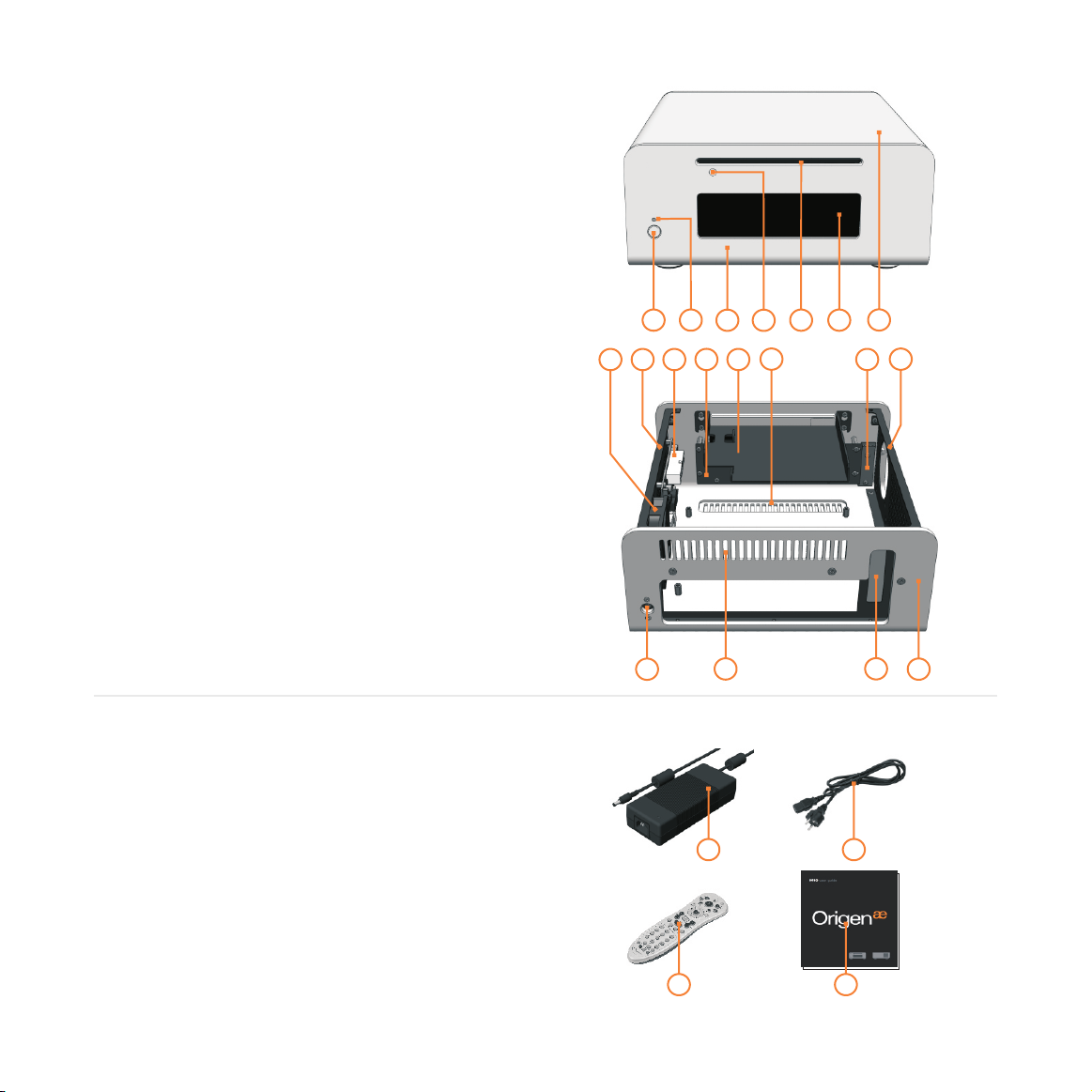
M10 overview
These are the main features and
controls of the M10 htpc enclosure.
Power button
1
Power LED
2
One piece aluminum chassis
3
ODD eject button
4
Slot for optical disk drive (ODD)
5
VFD/IR acryl window
6
Top panel
7
Right mount panel(DC to DC, 60mm fan)
8
60mm low dB intake fan
9
DC to DC
10
VF310 VFD/IR module
11
ODD Bracket
12
Bottom intake vent
13
Power button PCB (M-PWRB-P1)
14
Left mount panel(HDD, 60mm fan)
15
DC input
16
Back intake vent
17
LP bracket slot
18
1
2
3
8
9
10
11
12
5
4
13
7
6
15
14
4
Accessories
1
FPS150-AHAN1 (external adapter)
2
AC cord
3
RC153 philips remote control
4
User guide
5
Mounting screws
16
17
1
3
18
3
2
4
Page 5
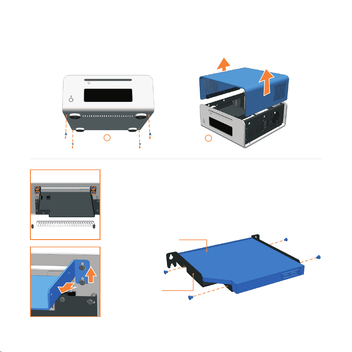
Opening the case
Remove the 4 fixing screws as indicated1. Carefully raise the panel as shown 2.
1
2
Optical disc drive installation
Loosen(no need to remove) the 4 fixing screws. Keyhole shaped holes
allow the ODD bracket to slide up and be lifted out over the screw
heads. install the ODD as shown.
12.7mm slot
load ODD
ODD
bracket
5
Page 6
Hard Drive installation
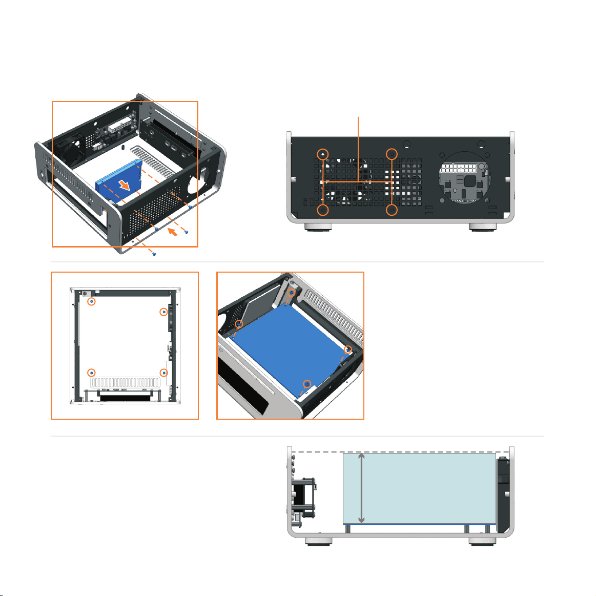
The M10 supports a 2.5 inch HDD or SSD. A HDD or SSD requires the 4 fixing screws on the
left panel of the chassis as shown.
Mounting holes
Left side view
Mainboard installation
If a Mini-itx board is to be
installed in the M10, the 4
spacer bolts supplied must
be used. Screw the bolts
Mounting
holes
into the bottom of chassis as
indicated.
Max height CPU cooler
The maximum size of CPU cooler is
80mm, the standard cooler of Intel or
AMD and third part CPU cooler of
below 80mm will be fitted in M10.
6
Max CPU cooler height
80mm
Right side view
Page 7
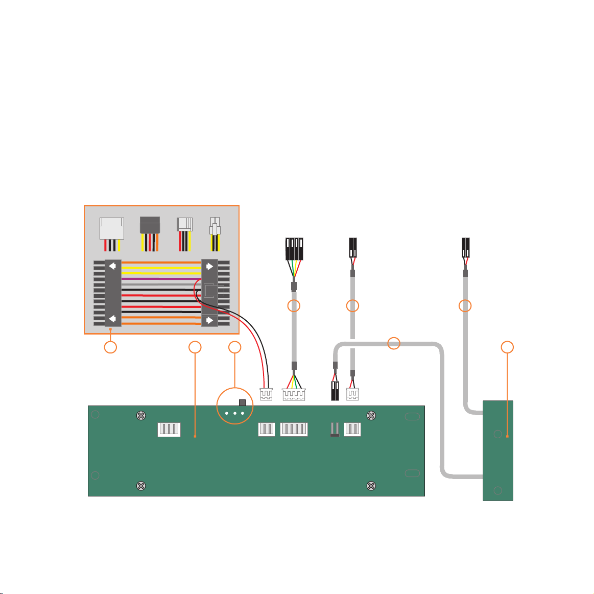
VF310 cable reference diagram
This is a general overview illustrating how the
internal PCBs interconnect. The VFD should be
switched to ‘S-GRAPH’ by default, which uses
the built in IR controller. Please refer to your
motherboard manual for the location of the
correct ports and header pins.
1 - VFD/IR module (VF310)
2 - IR selector switch ( )
S-GRAPH is default
3 - Main power button PCB (M-PWBT-P1)
4 - Standby ATX power cable (M-ATXS-C1)
5 - Internal USB cable (M-IUSB-C1)
6 - Power on/off cable (M-IPSW-C1)
7 - System LED cable (M-SLED-C1)
DC to DC
454
VF310
PHILLIPS
To USB
Header
24Pin on M/B
1 3
2
STBY
POWER
GND
5V STBY
USB
D-
VCC
S-GRAPH
PHILLIPS
GND
D+
To Motherboard
On/Off Header
6
IN OUT
PWR
SWITCH
To Motherboard
SYSTEM LED Header
7
6
M-PWBT-P1
7
Page 8
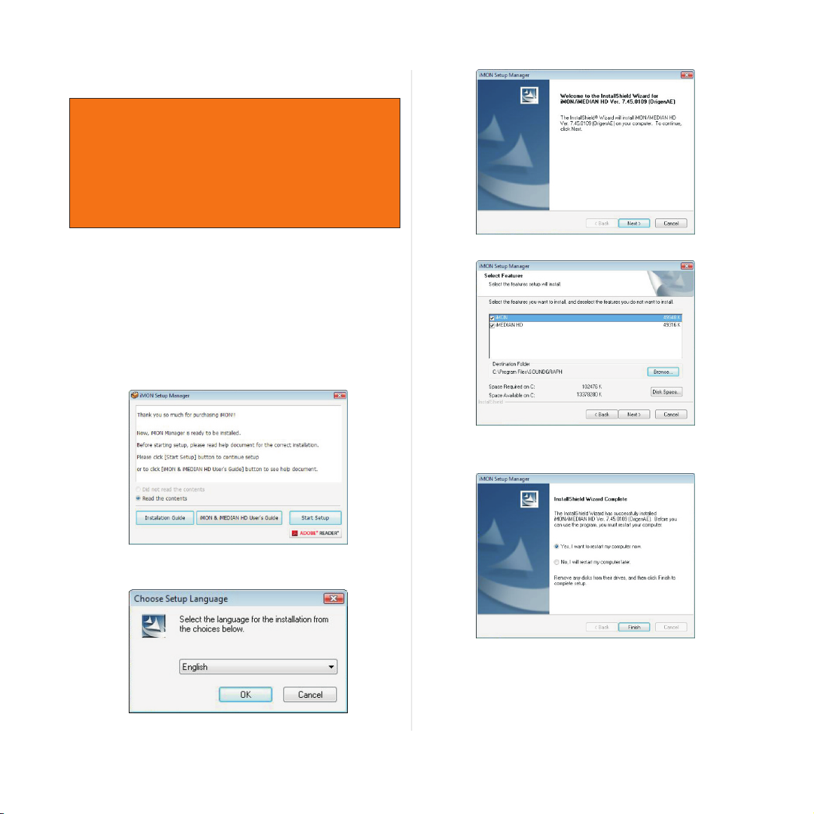
Installing VFD/IR Software
Read this notice before installation,
● The select switch must be a S-Graph in
VF310 back sides S-Graph and Philips.
● The USB(M-IUSB-C1) cable must be
connected to USB header pins.
● The 5V standby cable must be connected
● The display of VF310 cannot be shown
before installation.
1. Download the VF310 installation software from
our web-site or as attached following link.
http://www.origenae.co.kr/data/iMON_7_45_0109_OrigenAE.zip
2. Release the downloaded file in the location
which is suitable.
3. Installation the iMONsetup in folder.
6. Click ‘Next’.
7. Select the programs. (iMON is essential and
iMEDIAN HD is unessential)
4. After opening a read the concern, Click
‘Start Setup’ to continue.
5. Select the language.
8
8. Click finish to next setup now.
9. Reboot computer to activate VF310.
10. Please select the MCE remote from the
option page.
Installation is now completed.
Thank you.
Page 9
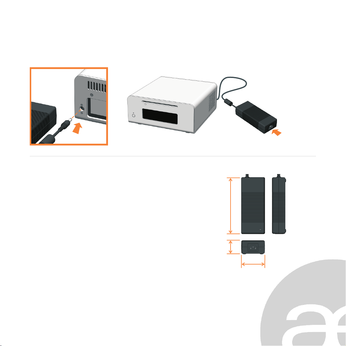
Connecting adapter
Connect external adapter(FSP150-AHAN1) to DC jack and AC cord to external adapter as shown.
AC c o r d in
Adapter specification (FSP150 - AHAN1)
in p u t
ra t e d i n p u t voltage
in p u t v o l t age range
in p u t f r e q uency range
in p u t c u r r ent
in p u t c u r r ent harmonic
ou t p u t
ou t p u t r a t ed voltage
ou t p u t c u r rent
ex t e rnal dimensio n s - 72 ( w ) x 1 7 1 ( h) x 40(d)
- 10 0 v a c / 2 4 0 v ac
- 90 v a c t o 2 6 4 v ac
- 47 H z t o 6 3 H z
- ≤2 . 0 A
- IE C 6 1 0 0 0 -3-2
- 12 v
- 0A t o 1 2 . 5 A
h
d
w
9
Page 10

Origen
Global HQ
#209 Baeksan B/D
763-2 Hengsin-Dong
Dukyang-Gu
Goyang City
Gyounggi-Do
412-220 South Korea
Website
www.origen .comae
 Loading...