

Page 1

Origen
S8 user guide
Page 2

Thank you for purchasing this Origen htpc enclosure. We recommend
that you read this user guide thoroughly before installation.
ae
Origen is not responsible for any damages due
to external causes, including but not limited to,
improper use, problems with electrical power,
accident, neglect, alteration, repair, improper
installation or improper testing.
SVUG.V1/05.27
Copyright © 2013 Technology
All rights reserved
ae
ae
Origen
Origen has rapidly grown to be one of the worlds leading HTPC enclosure
manufacturers since its inception in 2000. We were one of the first companies
with the vision to produce high end htpc enclosures that harmonise with
mainstream audio visual equipment, allowing the pc to leave the office
and fit effortlessly into the living room environment.
We are driven by the passion to produce exceptional products
that push technical and aesthetic boundaries to new levels.
For more information on all of our products,
visit www.origenae.com
ae
S8 user guide
Page 3

S8 overview
Opening the case
ODD cage removal
Hard drive installation
USB 3.0 ports connection
Optical disk drive installation
Metal sticker fitting instructions
Optical drive bezel installation
HDD cage removal
Max height CPU cooler
IR310 cable reference diagram
Installing IR Software
4
5
5
5
6
6
7
7
7
7
8
8
S8
index
Page 4

Power button
Power LED ring
IR receiver window
Top panel
Optical disk drive vezel
USB 3.0 ports
ODD eject button
Optical disk drive brackets
IR310 IR controller fixing point
Hard disk drive brackets
Top panel fixing screw
1 x 60mm low dB intake fan
1
2
3
4
5
6
7
8
9
10
11
12
S8 overview
These are the main features and
controls of the S8 htpc enclosure.
4
2
1
65
3
4
7
8
9
11
12
11
8 10
Page 5
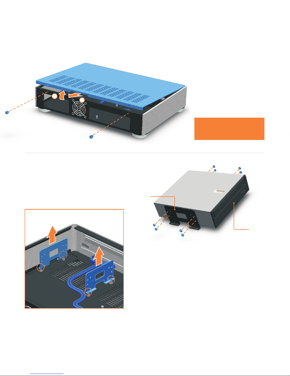
ODD cage removal
Remove left / right 4 fixing screws
completely from the chassis.
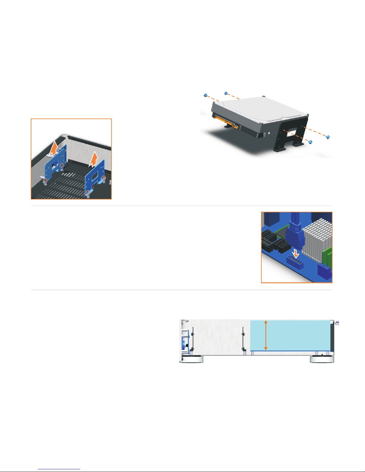
Optical disc drive installation
Separate the existing plastic drive bezel from
your ODD. The disc tray should be ejected and
requires some upward force to the bezel.
Put your ODD in left / right ODD bracket and fix
screws like picture. After fixing screws, assemble
ODD bracket to chassis. Secure all fixing screws
and check the eject button function.
1
2
5
Opening the case
Remove the thumb screws
as indicated. Carefully raise
the p
and
anel as shown (about
30mm is enough) pull
out to remove. Reverse the
procedure to replace.
DO NOT force upwards
as this could cause
damage to the top panel.
ODD
bracket
Optical
disk drive
Page 6

Optical disk drive bezel installation
The aluminum ODD bezel matches the finish of the case. The installation procedure requires
that the plastic drive bezel that comes fitted to your drive, be removed prior to installation.
Metal sticker fitting instructions
The drive format icon should also be fitted to the bezel before installation. The metal sticker sheet
supplied has Blu-ray, HD-DVD or DVD icons, depending on the format being used.
C
Ensure the bezel
is free from dirt of grease. Peel and fold back the yellow backing sheet, revealing only the part you
wish to use. arefully position the icon as central as possible, then apply even pressure over the
entire area. Peel off the plastic film (and unused icons) to reveal you handy work!
Check that the drive has been aligned correctly and that the can eject and close freely.tray
Peel the back off the adhesive foam strip on the rear of the aluminium bezel. Fold a cardboard
spacer around each end of the bezel, holding your thumb against the flaps as shown. With the
tray closed, position inside the drive opening and press firmly against the front of the tray to
ensure good adhesion. Eject the tray to remove the spacers.
TOP
TOP
foam
tape
6
Page 7
HDD cage removal
Remove left / right 4 fixing screws completely from
the chassis.
Hard drive installation
Put your HDD in Left / right HDD bracket and fix screws as
shown.
* The specification of ODD bracket and HDD bracket is same.
USB 3.0 connection
The S8 is allowed to use two USB 3.0 port by connecting to
mainboard as shown.
Refer to your mainboard user guide if the mainboard supports USB
3.0 socket.
7
Max height CPU cooler
The maximum size of CPU
cooler is 57mm as shown
picture.
Max height CPU cooler
57mm
Page 8
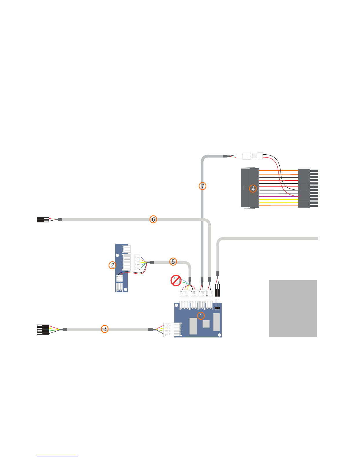
IR3 1 0 c a ble referen c e d i agram
Thi s is I R 310 module and cable connecti o n . En s u re al l ca b les connection as d i a gram.
Con t a c t sales@ori g e n ae.com for s p e c ial purchas e o f I r 310.
*Re mind tha t wrong ca b l e connec t i o n might be damage d to your P C compon e n t s.
Che c k / ensure cabl e c o n nection co r r e ctly as below.
Part list
1. IR310 module
2. S-FRIO-P3
3. S-IUSB-C2
4. S-ATXS-C1
5. S-IRIO-C1
6. S-IPSW-C1
7. S-ATXI-C1
8
From Chassis Power Switch
To Motherboard Power on/off Header
To USB Header
Page 9

Installing ir software
Download the IR310 installation software from
our web-site. www.origenae.com
Read this notice before installation.
- The USB (S-IUSB-C2) cable must be connected to USB
header pins. (See page 8)
- The 5V standby cable (S-ATXS-C1) cable must be
connected. (See page 8)
6. Click ‘Next’.
7. Select the programs. (iMON is essential and
iMEDIAN HD is unessential)
8. Click finish to next setup now.
9. Reboot computer.
10. Please select the MCE or iMON pad remote
from the option page.
Installation is now completed.
Thank you.
1. Download the VF310 installation software from
our web-site or as attached following link.
2. Release the downloaded file in the location
which is suitable.
3. Installation the iMONsetup in folder.
http://www.origenae.co.kr/data/data/iMON_8_12_1202.zip
4. After opening a read the concern, Click
‘Start Setup’ to continue.
5. Select the language.
9
Page 10

Global HQ
Website
#209 Baeksan B/D
763-2 Hengsin-Dong
Dukyang-Gu
Goyang City
Gyounggi-Do
412-220 South Korea
www.origen .comae
Origen
 Loading...