


Origen
S16T user guide

Thank you for purchasing this Origen htpc enclosure. We recommend
that you read this user guide thoroughly before installation.
ae
Origen has rapidly grown to be one of the worlds leading HTPC enclosure manufacturers since
its inception in 2000. We were one of the first companies with the vision to produce high end
htpc enclosures that harmonise with mainstream audio visual equipment, allowing the pc to
leave the office and fit effortlessly into the living room environment.
We are driven by the passion to produce exceptional products that push technical and aesthetic
boundaries to new levels. For more information on all of our products, visit www.origenae.com
ae
S16T overview
Opening the case
ODD cage removal
Optical disk drive installation
Metal sticker fitting instructions
Optical drive bezel installation
Hard drive installation
TFT controls / menu operation
Multi-format card reader & I/O ports
PCB/cable reference diagram
Touch panel software installation
VGA loop cable
Micro ATX standoffs
3
4
4
4
5
5
6
7
8
9
10
11
11
Origen is not responsible for any damages due
to external causes, including but not limited to,
improper use, problems with electrical power,
accident, neglect, alteration, repair, improper
installation or improper testing.
S16TUG.V1/09.07
Copyright © 2007 Technology.
ae
ae
Origen
S16T user guide

14
1
5
98
4
6
11
16 17 18 19
25
26
27 27
28
Power button
Blue LED ring
External TFT on/off (under chassis)
One piece aluminum chassis
7” TFT touch panel
Top panel
TFT menu controls
Optical disk drive (ODD) bezel
Soft-eject access panel
I/O ports/multi-format card reader
ODD eject button
IR receiver window
Door latch
Fixing point for HM100* (see 28)
IR receiver PCB
Intake vent
I/O ports/card reader PCB
ODD cage
TFT button PCB
4th HD mount bracket
Philips IR controller PCB
TFT module
Primary hard drive cage
Side intake vent
92mm low dB fan
Top panel fixing screw
80mm low dB fan
HM100* hard drive mount
(allows a 5th HD to be installed)
*optional accessory
1
2
3
4
5
6
7
8
9
10
11
12
13
14
15
16
17
18
19
20
21
22
23
24
25
26
27
28
S16T overview
These are the main features and
controls of the S16T htpc enclosure.
10
273
12 13
15
20 21 22 23 24
26
3

Opening the case
Remove the thumb screws
as indicated. Carefully raise
the p
and
anel as shown (about
30mm is enough) pull
out to remove. Reverse the
procedure to replace.
1
2
ODD cage removal
Remove the top fixing screw completely.
4 fixing
screws circled.
it to slide
back and be lifted out over the screw
heads, ready for ODD installation.
Loosen (no need to remove) the
Keyhole shaped holes
on the base of the cage allow
front I/O plate
DO NOT force upwards
as this could cause
damage to the top panel.
Optical disc drive installation
Unclip the existing plastic drive bezel from your
ODD. The disc tray should be ejected for this and
usually requires some upward force to the bezel.
Slide the optical disk drive through the front of
the cage. Before securing the drive screws,
check/adjust the ODD’s position in the chassis it should sit as close to the front I/O plate as
possible without the drive eject button becoming
depressed. Secure all fixing screws and double
check the eject button functions correctly.
ODD
cage
Optical
disk drive
Hard drive
mount
4

Optical disk drive (ODD) bezel installation
The aluminum ODD bezel matches the finish of the case. The installation procedure requires
that the plastic drive bezel that comes fitted to your drive, be removed prior to installation.
Metal sticker fitting instructions
Ensure the bezel
is free from dirt of grease. Peel and fold back the yellow backing sheet, revealing only the part you
wish to use. arefully position the icon as central as possible, then apply even pressure over the
entire area. Peel off the plastic film (and unused icons) to reveal you handy work!
The drive format icon should also be fitted to the bezel before installation. The metal sticker sheet
supplied has Blu-ray, HD-DVD or DVD icons, depending on the format being used.
C
TOP
TOP
foam
tape
Check that the drive has been aligned correctly and that the can eject and close freely.tray
Peel the back off the adhesive foam strip on the rear of the aluminium bezel. Fold a cardboard
spacer around each end of the bezel, holding your thumb against the flaps as shown. With the
tray closed, position inside the drive opening and press firmly against the front of the tray to
ensure good adhesion. Eject the tray to remove the spacers (a gentle tug may be required).
5

Hard Drive installation
The S16T supports 4 hard drives
as standard ; three in the primary
HD cage and one above the ODD.
. The mount
bracket is only needed for the drive
above the ODD and should be fitted
on the one side prior to installation.
*
Each HD requires four anti-vibration
mount screws, secured as shown,
which will isolate the drive from the
chassis once installed
mount
screw
mount
bracket
To install drives 1,2 and 3, begin by removing the two thumb screws...
To install the 4th drive above the optical drive...
*A fifth drive can be installed to the S16T using the HM100 hard drive mount (optional).
6

TFT controls / menu operation
OSD
[in orange]
The TFT controls are located behind
the chassis door. A second TFT on/off
button is discreetly located near the
power button on the underside of the
chassis. To configure the TFT, press
the button to bring up
the on screen display (OSD). Use the
buttons to navigate through
the 10 menu categories. Press the
button then where
appropriate use the and to increase
or decrease the value as desired.
Press the button again to confirm
the setting then repeat the process
until you have made all the required
adjustments. To
menu/set ( )
and
to select a category
exit the OSD, simply
locate the EXIT category and press the
button (after 10 seconds of inactivity
the OSD will exit automatically).
The screen shot guide below shows
the quickest route and the
adjustment sequence for
each of the OSD menu categories
(all assume you are not currently in the
menu, with the exception of EXIT).
[in grey]
TFT power on/off Value up
Menu/set Value down
1
Contrast.
Brightness.
Language
4
2
Phase.
5
V position.
4
H position.
Clock.
3
Exit.
Auto-adjust.
3
Factory reset.
2
1 BRIGHTNESS - adjusts the picture brightness.
2 CONTRAST - adjusts the picture contrast.
3 PHASE - adjusts the noise of the image.
4 CLOCK - adjusts video sampling clock.
5 H POSITION - adjusts the image horizontally.
6 V POSITION - adjusts the image vertically.
7 LANGUAGE - language selection.
8 AUTO - auto image adjust wizard.
9 RESET - resets to factory setting.
10 EXIT - exits the TFT menu.
7

1
4 7 8
6
53
2
1
1 Compact Flash Card TYPE I 20 Secure Digital Ultra II Plus Card 39 Memory Stick (Magic Gate / High
2 Compact Flash Card TYPE II 21 Secure Digital Card 45X Speed data transfer compatible)
3 Compact Flash Ultra Card TYPE I 45 X 22 Secure Digital PRO Card 66X 40 Memory Stick
4 Compact Flash Ultra Card TYPE I 80 X 23 Secure Digital Card 80X (Magic Gate / High Speed data transfer
5 Compact Flash Ultra Card TYPE I 120 X 24 Secure Digital Card 133X compatible with memory select function)
6 Compact Flash Ultra II Card TYPE I 25 Secure Digital Card 150X 41 Memory Stick Pro
7 Compact Flash Extreme Card 26 Mini Secure Digital Card 42 Magic Gate Memory Stick
8 Compact Flash Extreme III Card 27 Mini Secure Digital Ultra II Card 43 Magic Gate Memory Stick
9 Compact Flash ELITE PRO Card 28 Mini Secure Digital Card 80X 44 Memory Stick Pro HS
10 Compact Flash Ultimate Card 100X 29 Mini Secure Digital PRO Card 45 Memory Stick Pro Ultra II
11 Compact Flash Ultra-X Card 140X 30 Micro Secure Digital Card 46 Memory Stick Pro Extreme
12 IBM Micro Drive Card 31 Micro Secure Digital Ultra II Card 47 Memory Stick Pro Extreme III
13 Sony Micro Drive Card 48 Memory Stick Pro
32 Multi Media Card 49 Memory Stick Pro Duo
14 Smart Media Card 33 Multi Media PRO Card 50 Memory Stick Pro Duo HS
34 Multi Media Plus Card 51 Memory Stick Pro Duo
15 XD-Picture Card 35 Reduced Sized Multi Media Card 52 Memory Stick Duo (Magic Gate / High
36 Reduced Sized Multi Media Mobile Card Speed data transfer compatible)
16 Secure Digital Card 53 Memory Stick Pro Duo
17 Secure Digital Ultra II Card 37 Memory Stick 54 Magic Gate Memory Stick Duo
18 Secure Digital Extreme Card 38 Memory Stick 55 Magic Gate Memory Stick Duo
19 Secure Digital Extreme III Card (With memory select function) 56 Memory Stick ROM
1 - USB port
2 - 1394 port
3 - Multi format reader
4 - Compact flash reader
5 - Card reader power LED
6 - Activity indicator LED
7 - Audio in socket
8 - Audio out socket
Multi-format card reader & I/O ports
All the S range cases come fitted with a multi-format
card reader and front I/O port PCB which consist of
audio in and out, 1394 and two ports. A builtin USB hub powers the front USB ports as well as
2 internal connectors, which are used for the IR
controller, VFD or [TFT] touch panel, depending on
the model. The audio ports support both AC97 and
HD audio standards, while the card reader supports
all the card formats listed at the bottom of the page.
USB
NOTE: Card adapter required for some formats
8

PCB/cable reference diagram
This is a general overview illustrating
how the internal PCBs in the S16T
interconnect. Please refer to your
motherboard manual for the location
of the correct ports and header pins.
1 - TFT control button PCB
2 - TFT control (AD) board
3 - TFT [external] power on/off
4 - Main power button PCB
5 - IR receiver PBC
6 - Philips IR blaster output
7 - Philips IR control PCB
8 - Card reader/USB hub PCB
9 - Standby ATX power cable
MOLEX
[to PSU]
M/B
[1394]
M/B
[audio]
M/B [2xUSB]
M/B
SWITCH
1
8
9
76
2 3 4
VGA
5
M/B [ACPI]
(optional)
12V
VGA
USB
9
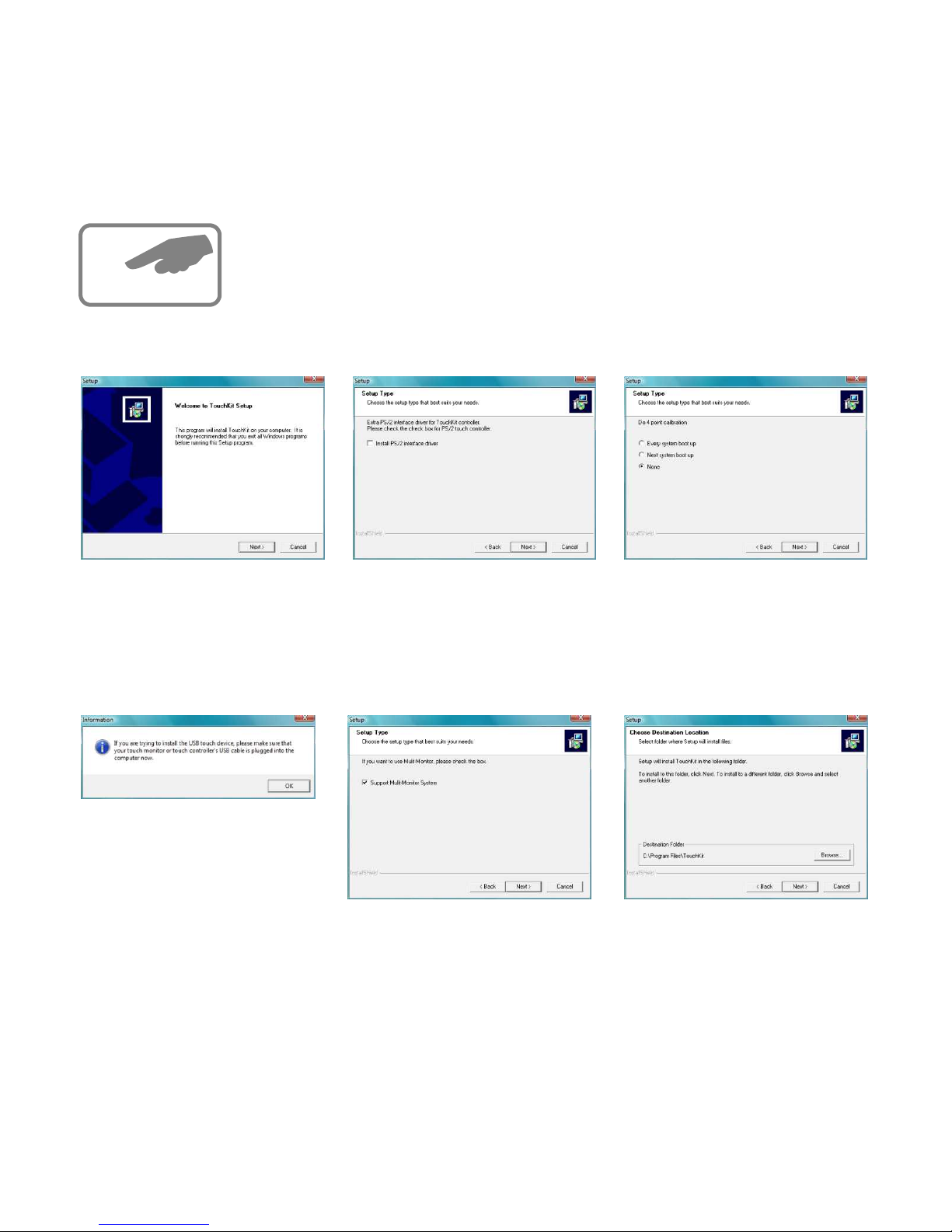
Touch panel software installation
> >
In order to use the touch panel, you must first install the software
from either an install CD or downloaded from our website (www.origenae.com
and navigate to support downloads s-series). To begin installation, double
click on the setup.exe file located in the folder.
touch panel
touch panel
1 After opening the setup.exe
file, the install will begin with
the above prompt. Click ‘Next’
to continue.
2 Ensure that ‘Install PS/2
interface driver’ is not
selected and click .‘Next’
3 Select ‘None’ and click .
After completing the install, the
software will perform
a 4 point calibration.
‘Next’
TouchKit
4 The touchscreen controller
should already be connected
if you have correctly
connected all cables inside
your chassis. Click ‘OK’.
5 If you intend to use spaning
mode with multiple monitors,
please select ‘Support MultiMonitor Systems’. Click
to continue.
‘Next’
6 Change the
software install folder if
required and click
to continue.
TouchKit
‘Next’
x
10

7 Change the Program
Folder name if required and
click to continue.‘Next’
8 Click ‘Yes’ to perform a
4 point calibration. This is
required for proper
operation.
touch
screen
9 The software will now scan
and install the touch screen
device. The calibration
procedure will follow.
TouchKit
10
X
X
To perform the calibration, press and hold down
the that blinks in the corner of the screen, until it
disappears. Repeat this procedure with each of the
4 ’s that appear. On completion of this, the touch
screen will be calibrated and ready for use.
x
x
VGA loop cable
This provides the VGA signal from your
graphics card to the 7” TFT via the VGA/
blaster expansion bracket & internal
cable. Fit the connectors as shown, then
secure by turning the finger screws.
Micro ATX stanoffs
spacer bolts supplied must be used.
Screw the bolts into the two standoffs as indicated.
If a micro ATX motherboard is to be installed in
the S16T, the
Spacer bolts MUST NOT BE INSTALLED with
a full ATX motherboard, as damage could occur.
VGA/blaster expansion bracket
11

Global HQ
Website
#209 Baeksan B/D
763-2 Hengsin-Dong
Dukyang-Gu
Goyang City
Gyounggi-Do
412-220 South Korea
www.origen .comae
Origen
 Loading...