


S14V / S16V user guideS10V /
Origen

S14V / S16V user guideS10V /
ae
Thank you for purchasing this Origen htpc enclosure. We recommend
that you read this user guide thoroughly before installation.
ae
Origen has rapidly grown to be one of the worlds leading HTPC enclosure
manufacturers since its inception in 2000. We were one of the first companies
with the vision to produce high end htpc enclosures that harmonise with
mainstream audio visual equipment, allowing the pc to leave the office
and fit effortlessly into the living room environment.
We are driven by the passion to produce exceptional products
that push technical and aesthetic boundaries to new levels.
For more information on all of our products,
visit www.origenae.com
ae
Origen is not responsible for any damages due
to external causes, including but not limited to,
improper use, problems with electrical power,
accident, neglect, alteration, repair, improper
installation or improper testing.
SVUG.V1/11.07
ae
Copyright © 2007 Technology
Origen
All rights reserved

index
S10V
S10V overview
Opening the case
Optical disk drive installation
Hard drive installation
Auxiliary access slot
IR Blaster installation
Multi-format card reader & I/O ports
PCB/cable reference diagram
Installing VFD/IR Software
S14V /
S14V overview
S16V overview
Opening the case
ODD cage removal
Optical disk drive installation
Metal sticker fitting instructions
Optical drive bezel installation
Hard drive installation
Auxiliary access slot [S14V]
IR Blaster installation [S14V]
Micro ATX standoffs [S16V only]
Multi-format card reader & I/O ports
PCB/cable reference diagram
Installing VFD/IR Software
S16V
4
7
9
9
11
11
12
13
14
5
6
7
7
7
8
8
10
11
11
11
12
13
14

S10V overview
These are the main features and
controls of the S10V htpc enclosure.
Power button
1
Power LED ring
2
One piece aluminum chassis
3
VFD/IR acryl window
4
Top panel
5
Slot for optical disk drive (ODD)
6
ODD eject button
7
Soft-eject access panel
8
I/O ports/multi-format card reader
9
Door latch
10
2 x 60mm low dB exhaust fans
11
I/O ports/card reader PCB
12
ODD bracket
13
Philips IR controller* fixing point
14
Hard drive mount brackets
15
VF210 VFD/IR module
16
HD chassis mount
17
2 x 60mm low dB intake fans
18
Auxiliary access slot
19
Top panel fixing screw
20
Philips IR blaster* fixing point
21
PSU intake vent (when isolated)
22
*part of an optional IR kit (IR221)
1
11 12 13 414 15 16 17
3
4
2
5
12
7
9
86
10
18
19
20
21
20
22
4
S14V overview
These are the main features and
controls of the S14V htpc enclosure.
Power button
1
Power LED ring
2
One piece aluminum chassis
3
VFD/IR acryl window
4
Top panel
5
Optical disk drive (ODD) bezel
6
Soft-eject access panel
7
I/O ports/multi-format card reader
8
ODD eject button
9
Door latch
10
Intake vent
11
I/O ports/card reader PCB
12
ODD cage
13
4th HD mount bracket
14
Philips IR controller* fixing point
15
VF210 VFD/IR module
16
Primary hard drive cage
17
Side intake vent
18
92mm low dB fan
19
Auxiliary access slot
20
Top panel fixing screw
21
Philips IR blaster* fixing point
22
60mm low dB fan
23
1
2
11 12 13 14 4 15 16 17 18
3
4
5
76
8 9
10
19
*part of an optional IR kit (IR221)
2320 21 23 2122
5

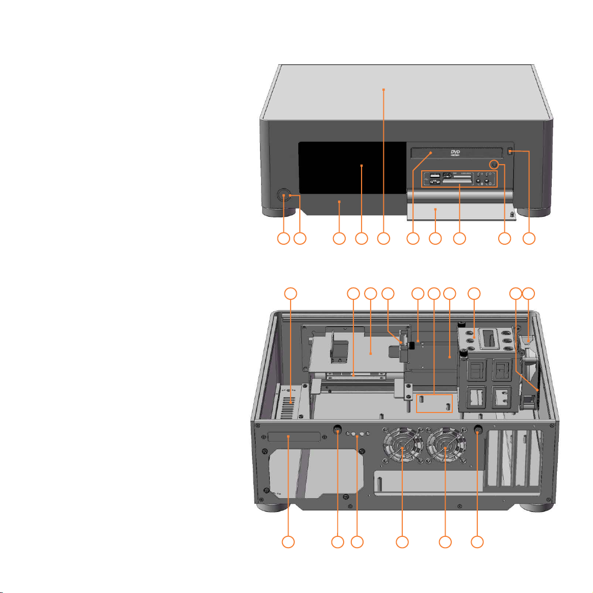
S16V overview
These are the main features and
controls of the S16V htpc enclosure.
Power button
1
Power LED ring
2
One piece aluminum chassis
3
VFD/IR acryl window
4
Top panel
5
Optical disk drive (ODD) bezel
6
Soft-eject access panel
7
I/O ports/multi-format card reader
8
ODD eject button
9
Door latch
10
Fixing point for HM100 (see 23)
11
Intake vent
12
I/O ports/card reader PCB
13
ODD cage
14
4th HD mount bracket
15
Philips IR controller* fixing point
16
VF210 VFD/IR module
17
Primary hard drive cage
18
Side intake vent
19
92mm low dB fan
20
Top panel fixing screw
21
80mm low dB fan
22
HM100 hard drive mount
23
+
+
(allows a 5th HD to be installed)
+
optional accessory
*part of an optional IR kit (IR221)
1
2
11
3
4
5
12 13 14 15 4 16 17 18
76
8 9
19
10
20
23
21
22
22
21
6

Opening the case
Remove the thumb screws
as indicated. Carefully raise
the p
1
2
anel as shown (about
30mm is enough) pull
and
out to remove. Reverse the
procedure to replace.
DO NOT force upwards
as this could cause
damage to the top panel.
ODD cage removal [S14V/S16V]
Remove the top fixing screw completely.
Loosen (no need to remove) the
screws circled.
Keyhole shaped holes
on the base of the cage allow
4 fixing
it to slide
back and be lifted out over the screw
heads, ready for ODD installation.
front I/O plate
Hard drive
mount
ODD
cage
Optical
disk drive
Optical disc drive installation [S14V/S16V]
Unclip the existing plastic drive bezel from your
ODD. The disc tray should be ejected for this and
usually requires some upward force to the bezel.
Slide the optical disk drive through the front of
the cage. Before securing the drive screws,
check/adjust the ODD’s position in the chassis it should sit as close to the front I/O plate as
possible without the drive eject button becoming
depressed. Secure all fixing screws and double
check the eject button functions correctly.
7

Metal sticker fitting instructions [S14V/S16V]
The drive format icon should also be fitted to the bezel before installation. The metal sticker sheet
supplied has Blu-ray, HD-DVD or DVD icons, depending on the format being used.
Ensure the bezel
is free from dirt of grease. Peel and fold back the yellow backing sheet, revealing only the part you
wish to use. arefully position the icon as central as possible, then apply even pressure over the
C
entire area. Peel off the plastic film (and unused icons) to reveal you handy work!
TOP
Optical disk drive (ODD) bezel installation [S14V/S16V]
The aluminum ODD bezel matches the finish of the case. The installation procedure requires
that the plastic drive bezel that comes fitted to your drive, be removed prior to installation.
TOP
foam
tape
Check that the drive has been aligned correctly and that the can eject and close freely.tray
Peel the back off the adhesive foam strip on the rear of the aluminium bezel. Fold a cardboard
spacer around each end of the bezel, holding your thumb against the flaps as shown. With the
tray closed, position inside the drive opening and press firmly against the front of the tray to
ensure good adhesion. Eject the tray to remove the spacers (a gentle tug may be required).
8

front I/O plate
Optical disc drive installation [S10V]
Loosen (no need to remove) the 4 fixing screws
allow to slide up and be lifted out over the screw
heads. Install the ODD as shown.
standard 40 pin connecter. Before securing the drive screws, check
the ODD’s position in the chassis - it should sit as close to the front I/O
plate as possible without the drive eject button becoming depressed.
Secure all fixing screws and check the eject button functions correctly.
the ODD bracket
The IDE adapter will allow for the
. Keyhole shaped holes
12.7mm slot
load ODD
ODD
bracket
Hard Drive installation [S10V]
The S10V supports 2 hard drives. Each HD requires four anti-vibration screws,
as shown, which will isolate the drive from the chassis once installed
is push fitted over the mount screws on the one side only. The drive may then be positioned
between the chassis mounts as shown, and gently pushed into place, taking care not to
damage the rubber on the mount screws. One thumb screw will secure the hard drive in place.
. A single mount bracket
secured
IDE
adapter
mount
bracket
mount
screw
9

Hard Drive installation [S14V/S16V]
The S14V and S16V support up to
4 hard drives*, three in the primary
HD cage and one above the ODD.
Each HD requires four anti-vibration
mount screws, secured as shown,
which will isolate the drive from the
chassis once installed
. The mount
bracket is only needed for the drive
above the ODD and should be fitted
on the one side prior to installation.
To install drives 1,2 and 3, begin by removing the two thumb screws...
mount
screw
mount
bracket
10
To install the 4th HD above the optical drive...
*A fifth drive can be installed to the S16V, using the HM100 hard drive mount (optional).

Auxiliary access slot [S10V/S14V]
The S14V & S10V an auxiliary access slot
features
on the back of the chassis, which is designed to fit
all expansion brackets that are supplied with other
OrigenAE products. To install, the bracket must first be
unscrewed from the PCB & re-attached ‘back-to-front’
before fixing to the auxiliary slot. This access point
could also aid any custom expansion, where external
connectivity with a component or the M/B is required.
180
o
Separate the PCB
from the OrigenAE
expansion bracket.
Flip the bracket 180
degrees and re-fit
it ‘back-to-front’.
IR Blaster installation [S10V/S14V]
Both the S10V & S14V have an
IR blaster fixing point on the
rear of the chassis, for when the
optional Philips IR solution is used.
This allows for more flexibility
when spare expansion slots are
not available. Unscrew the blaster
PCB from the expansion bracket
and re-install as shown.
Micro ATX standoffs [S16V]
If a micro ATX motherboard
is to be installed in the S16V,
the
spacer bolts supplied
must be used. Screw the
bolts into the two shorter
standoffs as indicated.
Spacer bolts MUST NOT
BE INSTALLED when a full
ATX motherboard is used
as damage could occur.
11

Multi-format card reader & I/O ports
All the S range cases come fitted with a multi-format
card reader and front I/O port PCB which consist of
audio in and out, 1394 and two ports. A built-
USB
in USB hub powers the front USB ports as well as
2 internal connectors, which are used for the IR
controller, VFD or [TFT] touch panel, depending on
the model. The audio ports support both AC97 and
HD audio standards, while the card reader supports
all the card formats listed at the bottom of the page.
1
2
53
6
1 - USB port
2 - 1394 port
3 - Multi format reader
4 - Compact flash reader
5 - Card reader power LED
6 - Activity indicator LED
7 - Audio in socket
8 - Audio out socket
1 Compact Flash Card TYPE I 20 Secure Digital Ultra II Plus Card 39 Memory Stick (Magic Gate / High
2 Compact Flash Card TYPE II 21 Secure Digital Card 45X Speed data transfer compatible)
3 Compact Flash Ultra Card TYPE I 45 X 22 Secure Digital PRO Card 66X 40 Memory Stick
4 Compact Flash Ultra Card TYPE I 80 X 23 Secure Digital Card 80X (Magic Gate / High Speed data transfer
5 Compact Flash Ultra Card TYPE I 120 X 24 Secure Digital Card 133X compatible with memory select function)
6 Compact Flash Ultra II Card TYPE I 25 Secure Digital Card 150X 41 Memory Stick Pro
7 Compact Flash Extreme Card 26 Mini Secure Digital Card 42 Magic Gate Memory Stick
8 Compact Flash Extreme III Card 27 Mini Secure Digital Ultra II Card 43 Magic Gate Memory Stick
9 Compact Flash ELITE PRO Card 28 Mini Secure Digital Card 80X 44 Memory Stick Pro HS
10 Compact Flash Ultimate Card 100X 29 Mini Secure Digital PRO Card 45 Memory Stick Pro Ultra II
11 Compact Flash Ultra-X Card 140X 30 Micro Secure Digital Card 46 Memory Stick Pro Extreme
12 IBM Micro Drive Card 31 Micro Secure Digital Ultra II Card 47 Memory Stick Pro Extreme III
13 Sony Micro Drive Card 48 Memory Stick Pro
32 Multi Media Card 49 Memory Stick Pro Duo
14 Smart Media Card 33 Multi Media PRO Card 50 Memory Stick Pro Duo HS
34 Multi Media Plus Card 51 Memory Stick Pro Duo
15 XD-Picture Card 35 Reduced Sized Multi Media Card 52 Memory Stick Duo (Magic Gate / High
36 Reduced Sized Multi Media Mobile Card Speed data transfer compatible)
16 Secure Digital Card 53 Memory Stick Pro Duo
17 Secure Digital Ultra II Card 37 Memory Stick 54 Magic Gate Memory Stick Duo
18 Secure Digital Extreme Card 38 Memory Stick 55 Magic Gate Memory Stick Duo
19 Secure Digital Extreme III Card (With memory select function) 56 Memory Stick ROM
1
4 7 8
12
NOTE: Card adapter required for some formats

PCB/cable reference diagram
This is a general overview illustrating
how the internal PCBs interconnect.
Grey
PCBs/cables indicate they come as part
of an optional IR kit
. The VFD should be
switched to ‘IR Trans’ by default, which
uses The LED
the built in IR controller.
switch toggles this feedback feature ON
(2) and OFF (1). Please refer to your
motherboard manual for the location of
the correct ports and header pins.
1 - VFD/IR Module (VF210)
2 - [VFD] IR selector switch (IR Trans is default)
3 - [VFD] LED switch (IR Trans: 2=ON 1=OFF)
4 - Main power button PCB
5 - Standby power ‘Y’ cable
6 - Philips IR blaster output (optional)
7 - Philips IR control PCB (optional)
8 - Card reader/USB hub PCB
9 - Standby ATX power cable
1
M/B [ACPI]
(optional)
MOLEX
[to PSU]
5
4
2
M/B
IR TRANS
PHILLIPS
3
2 1
M/B [2xUSB]
M/B
[1394]
M/B
[audio]
6
7
8
9
13

Installing VFD/IR Software
Download the latest IR Trans software from our website, extract the files then follow these steps...
1 Begin the
installer by double
clicking the IR
Trans setup file
3 The main IR Trans installer page
will load, click next to continue
2 Installer will
unpack and verify
its contents
4 Please read installation notes then click next
14
5 Ensure that you’ve selected the MCE Display
Driver from the options page then click next
6 Select the destination folder. We recommend
using the default location, then click next

7 You can change the default menu group
setting then click next to continue
8 You are not ready to start the file installation,
click next to begin
9 Files and setting will now be copied and
applied, please wait for this to finish
10 Installation is now complete
and a reboot is required
15

Origen
Global HQ
#209 Baeksan B/D
763-2 Hengsin-Dong
Dukyang-Gu
Goyang City
Gyounggi-Do
412-220 South Korea
Website
www.origen .comae
 Loading...