

Page 1

Network converter EtherCAT compatible
NETC01-ECT
USER MANUAL
HM-60301
Thank you for purchasing an Oriental Motor product.
This manual describes product handling procedures and safety precautions.
•Please read it thoroughly to ensure safe operation.
•Always keep the manual where it is readily available.
Page 2

1 Safety precautions ................................................. 3
2 Overview of the product ...................................... 5
2-1 System conguration ...................................................5
2-2 What is EtherCAT? .........................................................5
3 Introduction ............................................................ 7
4 Preparation ............................................................. 8
4-1 Checking the product ..................................................8
4-2 Names and functions of parts ...................................8
5 Installation ............................................................10
5-1 Location for installation ............................................ 10
5-2 Installation method .................................................... 10
5-3 Installing and wiring in compliance with
EMC Directive ............................................................... 11
6 Connection ............................................................ 13
6-1 Connection example ................................................. 13
6-2 Connecting the power supply and
grounding the
6-3 Connecting the RS-485 communication
cable ................................................................................ 14
6-4 Connecting the EtherCAT communication
cable ................................................................................ 15
6-5 Connecting the data setter ..................................... 15
NETC01-ECT
............................... 13
7 Guidance................................................................16
8 Setting ....................................................................21
8-1 Transmission rate of RS-485 communication ... 21
8-2 Node address of EtherCAT ....................................... 21
9 Basic function .......................................................22
9-1 Remote I/O list.............................................................. 22
9-2 Remote register list ....................................................23
9-3 Remote monitor list ...................................................27
9-4 Objects of the
9-5 Read, write, save of parameters ............................. 33
9-6 Basic operating procedures ....................................34
NETC01-ECT
................................ 30
10 Specications of RS-485 communication ........37
10-1 Operation mode .......................................................... 37
10-2 RS-485 communication conguration ................ 37
10-3 RS-485 communication process and
scan time ........................................................................ 37
10-4 RS-485 communication status ...............................39
11 Troubleshooting................................................... 40
11-1 Alarms .............................................................................40
11-2 EtherCAT communication error ............................. 41
11-3 Warning .......................................................................... 41
11-4 Relationship with the RS-485 communication
compatible product ................................................... 42
12 Inspection ..............................................................43
13 General specications .........................................44
14 Operation using the
14-1 Overview of the
14-2 Names and functions of parts ................................ 46
14-3 How to read the display ............................................46
14-4
OPX-2A
14-5 Screen transitions .......................................................48
14-6 Monitor mode .............................................................. 50
14-7 Parameter mode ..........................................................51
14-8 Copy mode .................................................................... 52
error display ............................................... 47
OPX-2A
OPX-2A
............................ 45
........................................45
15 CoE communication area ...................................53
15-1 CoE communication area ......................................... 53
16 Accessories ............................................................ 61
2
▌
Page 3
1 Safety precautions
The precautions described below are intended to prevent danger or injury to the user and other personnel through safe, correct use
of the product. Use the product only after carefully reading and fully understanding these instructions.
Handling the product without observing the instructions that accompany a "Warning" symbol may
result in serious injury or death.
Handling the product without observing the instructions that accompany a “Caution” symbol may result
in injury or property damage.
General
•Do not use the product in explosive or corrosive environments, in the presence of ammable gases, locations subjected to
splashing water, or near combustibles. This may cause re or injury.
•Assign qualied personnel the task of installing, wiring, operating/controlling, inspecting and troubleshooting the product.
Failure to do so my result in re, injury or damage to equipment.
Connection
•Keep the input power voltage of the
•For the power supply use a DC power supply with reinforced insulation on its primary and secondary sides. Failure to do so may
result in electric shock.
•Connect the cables securely according to the wiring diagram. Failure to do so may result in re.
•Do not forcibly bend, pull or pinch the cable. This may cause re. Applying stress to the connection area of the connectors may
cause damage to the product.
NETC01-ECT
within the specied range. Failure to do so may result in re.
Safety precautions
Operation
•Turn o the
and may cause injury or damage to equipment.
•When an alarm of the
equipment.
NETC01-ECT
power in the event of a power failure. Or the motor may suddenly start when the power is restored
NETC01-ECT
is generated, stop the motor. Failure to do so may result in re, injury or damage to
Repair, disassembly and modication
•Do not disassemble or modify the
branch or sales oce from which you purchased the product.
NETC01-ECT
. Doing so may cause injury. Refer all such internal inspections and repairs to the
General
•Do not use the
•Keep your ngers and objects out of the openings in the
NETC01-ECT
beyond its specications. This may cause injury or damage to equipment.
NETC01-ECT
. Failure to do so may result in re or injury.
Installation
•Install the
•Keep the area around the
•Leave nothing around the
NETC01-ECT
in an enclosure. Failure to do so may result in injury.
NETC01-ECT
NETC01-ECT
free of combustible materials. Failure to do so may result in re or a skin burn(s).
that would obstruct ventilation. Failure to do so may result in damage to equipment.
Connection
•The power supply connector (CN1), EtherCAT communication input port (ECAT IN), EtherCAT communication output port (ECAT
OUT), data edit connector (CN2) and RS-485 communication connector (CN6) of the
When grounding the positive terminal of the power supply, do not connect any equipment (PC, etc.) whose negative terminal is
grounded. Doing so may cause the
NETC01-ECT
and the equipment to short, damaging both.
NETC01-ECT
are not electrically insulated.
Operation
•Use the
•When operating the product, do so after making preparations that an emergency stop can be performed at any time. Failure to
•Set a suitable operation speed and acceleration/deceleration rate. Improper setting may cause loss of the motor synchronism
•Immediately when trouble has occurred, stop running and turn o the
NETC01-ECT
do may result in injury.
and moving the load to an unexpected direction, which may result in injury or damage to equipment.
injury.
in combination with the designated applicable product. Failure to do so may result in re.
NETC01-ECT
power. Failure to do so may result in re or
3
▐
Page 4

Safety precautions
•Static electricity may cause the
is input. Always use an insulated screwdriver to adjust the switches of the
NETC01-ECT
to malfunction or suer damage. Do not touch the
NETC01-ECT
.
Disposal
•To dispose of the
components as industrial waste. Contact your nearest Oriental Motor oce if you have any questions.
NETC01-ECT
, disassemble it into parts and components as much as possible and dispose of individual parts/
NETC01-ECT
while the power
4
▌
Page 5
2 Overview of the product
Overview of the product
The
NETC01-ECT
By converting the EtherCAT communication protocol of the upper level to the RS-485 communication protocol of the lower
level, Oriental Motor RS-485 communication compatible products can be operated via EtherCAT communication. The RS-485
communication protocol of the lower level is Oriental Motor's own RS-485 communication protocol.
Also, using a
When the
and
NETC01-ECT
is a communication converter between EtherCAT and RS-485 communication.
MEXE02
MEXE02
or accessory
is used, a communication cable for data setting software
. Be sure to purchase it.
OPX-2A
The NETC01-ECT
•For details about terms and explanations of EtherCAT communication, refer to the operating manual of the EtherCAT master
device.
•The
NETC01-ECT
perform synchronization control via EtherCAT communication.
is not compatible with the Distributed Clocks of the EtherCAT communication specications, so it cannot
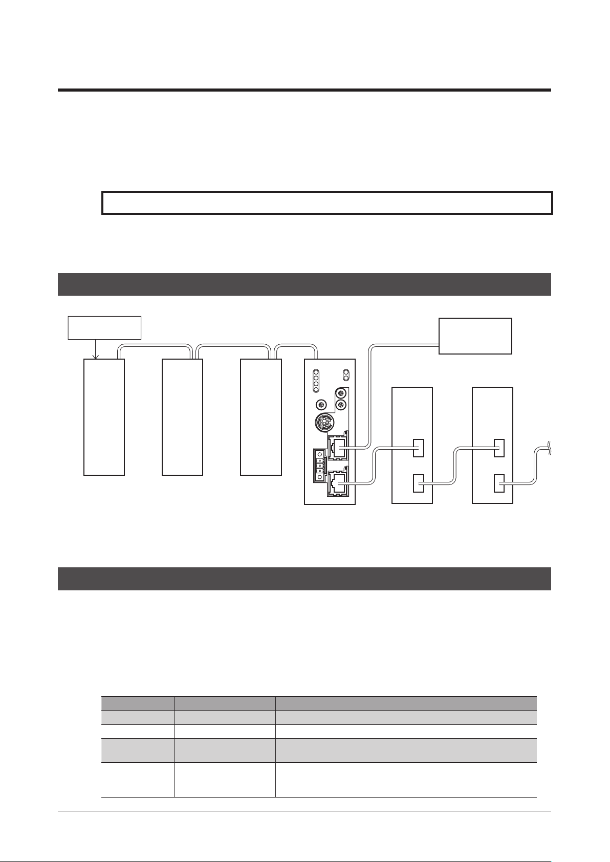
2-1 System conguration
Termination resistor
ON *
RS-485 communication
, the communication time can be monitored.
CC05IF-USB
(accessory) is needed to connect a PC
is operated as an I/O device on EtherCAT communication.
EtherCAT
communication
Master device
RS-485
communication
compatible product
RS-485
communication
compatible product
2-2 What is EtherCAT?
EtherCAT is an open and high-speed industrial network system that conforms to Ethernet (IEEE 802.3).
Since each node transmits Ethernet frames at high speed, it can achieve a short communication cycle time.
Object dictionary
The object dictionary consists of the data type objects, CoE communication objects, prole objects, and manufacturer-specic
objects.
The objects are assigned indexes of four-digit hexadecimal numbers and consisted of four areas described in the table below.
CoE Index Object dictionary area Description
0000h to 0FFFh Data type area Denition objects of data type.
1000h to 1FFFh CoE communications area Common area for devices to use CoE protocol.
2000h to 5FFFh Manufacturer-specic area
6000h to FFFFh Prole area
RS-485
communication
compatible product
Specic objects for devices that can be assigned freely by manufacturer.
The
Objects dened by each prole.
Example: CiA402 drive protocol, etc.
The
NETC01-ECT
* The termination resistor for RS-485 communication is built into the product.
NETC01-ECT
NETC01-ECT
uses this area.
does not use this area.
EtherCAT
communication
compatible product
EtherCAT
communication
compatible product
5
▐
Page 6

Overview of the product
zAbout description of the type
The type represents the data type of objects. Abbreviations described in the table below are used in this manual.
Data type Abbreviation Description Range of value
Integer8 INT8 8-bit signed data
Integer16 INT16 16-bit signed data
Integer32 INT32 32-bit signed data
Unsigned8 U8 8-bit unsigned data 0 to 255
Unsigned16 U16 16-bit unsigned data 0 to 65,535
Unsigned32 U32 32-bit unsigned data 0 to 4,294,967,295
VisibleString STRING Character string
Manufacturer-specic area list
128 to 127
−
32,768 to 32,767
−
2,147,483,648 to 2,147,483,647
−
−
Objects used in the
CoE Index
Start End
2000h 21FFh
2200h 23FFh
2400h 25FFh
2600h 27FFh
2800h 29FFh
2A00h 2BFFh
2C00h 2FFFh
3000h 3BFFh
3C00h 3FFFh
4000h 4FFFh
5000h 5FFFh
NETC01-ECT
Sub-
index
PDO possible/
not possible
− −
− −
−
−
−
−
−
− −
−
− −
− −
are composed as follows.
Area name Description
Reserve This is a reserved area.
Reserve This is a reserved area.
Possible Remote I/O (IN)
Possible Remote I/O (OUT)
Possible Remote register *
Possible Remote monitor *
Possible
Possible
NETC01-ECT
(RW) *
Reserve This is a reserved area.
NETC01-ECT
maintenance (W) *
Reserve This is a reserved area.
Reserve This is a reserved area.
parameter
monitor (R),
This is an input area (
remote I/O. This area is used by NET-OUT of the RS-485
communication compatible product.
This is an output area (Master ->
remote I/O. This area is used by NET-IN of the RS-485
communication compatible product.
This is an area for mapping the remote register area to
the PDO to access the register. There are objects for each
address number.
This is an area for mapping the remote monitor
area to the PDO to monitor the status of the RS-485
communication compatible product. Multiple monitors
can be performed to the same address number.
This is an area (Read/Write) for accessing to parameters
of the
NETC01-ECT
This is an access area for performing monitor and
maintenance of the
command is executed by Read, and the maintenance
command is executed by Write.
NETC01-ECT
.
NETC01-ECT
-> Master) of
NETC01-ECT
. The monitor
) of
* You can access by the SDO when not mapping to the PDO.
Providing the ESI File
The ESI le (EtherCAT Slave Information le) is the one that describes the specic information of the EtherCAT slave products in XML
format. By importing the ESI le to the EtherCAT Congration Tool of the PLC (programmable controller), the settings of EtherCAT
communication can be performed before you receive the
The ESI le can be downloaded from Oriental Motor Website Download Page.
6
▌
NETC01-ECT
.
Page 7

3 Introduction
Before use
Only qualied personnel should work with the product.
Use the product correctly after thoroughly reading the section "1 Safety precautions" on p.8.
The product described in this manual has been designed and manufactured to be incorporated in general industrial equipment.
Do not use for any other purpose. For the power supply of the
its primary and secondary sides. Oriental Motor Co., Ltd. is not responsible for any damage caused through failure to observe this
warning.
NETC01-ECT
Introduction
, use a DC power supply with reinforced insulation on
Operating Manuals for the
Operating manuals for the
After reading the following manuals, keep them in a convenient place so that you can reference them at any time.
zNetwork converter EtherCAT compatible
This manual explains the function, installation and connection of the
For the command code or remote I/O of the RS-485 communication compatible product that can be connected to the
, refer to the USER MANUAL or Function Edition of the corresponding RS-485 communication compatible product.
ECT
The OPERATING MANUAL and Function Edition does not come with the product. For details, contact your nearest Oriental Motor
sales oce or download from Oriental Motor Website Download Page.
zNetwork converter EtherCAT compatible
NETC01-ECT
NETC01-ECT
are listed below.
NETC01-ECT
NETC01-ECT
USER MANUAL (this document)
NETC01-ECT
as well as operating method.
OPERATING MANUAL
NETC01-
(Supplied with the product)
This manual explains safety precautions, connector pin assignments and others.
zData setting software
This manual explains the parameter setting method and monitor function using the
MEXE02
OPERATING MANUAL
MEXE02
.
Notation on operating manual
The items under this heading contain important handling instructions that the user should observe to ensure
safe use of the product.
The items under this heading contain related information and contents to gain a further understanding of the
text in this manual.
CE Marking
Although this product is exempt from the Low Voltage Directive since the input power supply voltage is 24 VDC, perform the
installation and connection as follows.
•This product is designed and manufactured to be incorporated in equipment. Install the product in an enclosure.
•For the power supply of the
•Overvoltage category: I
•Pollution degree: 2
•Degree of protection: IP20
NETC01-ECT
, use a DC power supply with reinforced insulation on its primary and secondary sides.
zEMC Directive
This product has received EMC compliance under the conditions specied in "Example of installation and wiring for the NETC01-ECT"
on p.12.
Since the conformity to the EMC Directive of the customer's equipment will vary depending on such factors as other control-system
devices used together with the
the customer must verify through EMC measurements of the nished equipment after installing all parts including the
.
ECT
NETC01-ECT
, as well as conguration of electrical components, wiring, and installation condition,
NETC01-
Applicable standards
EMI: EN 61000-6-4, EN 55011 group 1 class A
EMS: EN 61000-6-2
Hazardous substances
The products do not contain the substances exceeding the restriction values of RoHS Directive (2011/65/EU).
7
▐
Page 8
Preparation
4 Preparation
This chapter explains the items you should check, as well as the name and function of each part.
4-1 Checking the product
Verify that the items listed below are included. Report any missing or damaged items to the branch or sales oce from which you
purchased the product.
Verify the model number of the purchased product against the number shown on the package label.
NETC01-ECT
•
•CN1 connector (3 pins) .......................1 pc.
•RS-485 communication cable ..........2 pcs. [0.1 m (3.94 in.), 0.25 m (9.84 in.) each 1 pc.]
•OPERATING MANUAL........................... 1 copy
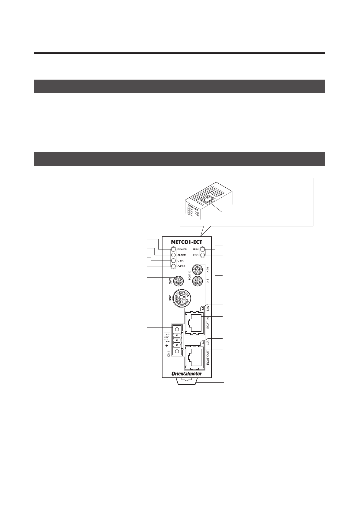
4-2 Names and functions of parts
....................................... 1 unit
RS-485
communication
Connect the RS-485
POWER LED (Green)
ALARM LED (Red)
C-DAT LED (Green)
C-ERR LED (Red)
RS-485 communication transmission
rate setting switch (SW1)
Data edit connector
(CN2)
Power supply input connector
(CN1)
RUN LED (Green)
ERR LED (Red)
Node address setting switches
(ECAT ID ×1, ×10)
L/A LED (Green)
EtherCAT communication input port
(ECAT IN)
L/A LED (Green)
EtherCAT communication output port
(ECAT OUT)
DIN lever
connector (CN6)
communication cable.
8
▌
Page 9

Preparation
Name Description Page
POWER LED (Green) This LED is lit while the power is input.
ALARM LED (Red)
C-DAT LED (Green)
C-ERR LED (Red) This LED is lit when an error was occurred via RS-485 communication.
RUN LED (Green)
ERR LED (Red)
L/A LED (Green)
Power supply connector (CN1) Connects a 24 VDC power supply. p.13
Data edit connector (CN2)
EtherCAT communication input port
(ECAT IN)
EtherCAT communication output port
(ECAT OUT)
RS-485 communication transmission
rate setting switch (SW1)
Node address setting switched
(ECAT ID ×1, ×10)
This LED blinks when an alarm generates. It is possible to check the
generated alarm by counting the number of times the LED blinks.
This LED is lit while transmitting and receiving data via RS-485
communication.
These LEDs indicate the status of EtherCAT communication. p.41
Connects a PC in which the
.
OPX-2A
This is a connector to perform EtherCAT communication. Connect to the
master device.
This is a connector to perform EtherCAT communication. Connect to the
following slave.
Sets the transmission rate of RS-485 communication.
Factory setting: 7
Sets the node address of the EtherCAT communication in the 0 to 255 (00h
to FFh) range.
10: Set the upper
×
1: Set the lower
×
Factory setting: 1 (×10: 0, ×1: 1)
MEXE02
has been installed, or an accessory
−
p.40
−
−
p.15
p.15
p.15
p.14
p.21
9
▐
Page 10

Installation
5 Installation
This chapter explains the installation location and installation method of the
The installation and wiring methods in compliance with the EMC Directive are also explained.
5-1 Location for installation
The
NETC01-ECT
that provides easy access for inspection. The location must also satisfy the following conditions:
•Inside an enclosure that is installed indoors (provide vent holes)
•Operating ambient temperature 0 to +40 °C (+32 to +104 °F) (non-freezing)
•Operating ambient humidity 85% or less (non-condensing)
•Area that is free of explosive atmosphere or toxic gas (such as sulfuric gas) or liquid
•Area not exposed to direct sun
•Area free of excessive amount of dust, iron particles or the like
•Area not subject to splashing water (rain, water droplets), oil (oil droplets) or other liquids
•Area free of excessive salt
•Area not subject to continuous vibration or excessive shocks
•Area free of excessive electromagnetic noise (from welders, power machinery, etc.)
•Area free of radioactive materials, magnetic elds or vacuum
•1000 m (3300 ft.) or lower above sea level
has been designed and manufactured to be incorporated in equipment. Install it in a well-ventilated location
5-2 Installation method
Install the
There must be a clearance of at least 50 mm (1.97 in.) in the horizontal and
vertical directions, between the
equipment within the enclosure.
When installing two or more units of the
to install them closely in the horizontal direction. Provide a minimum clearance
of 50 mm (1.97 in.) in the vertical direction.
NETC01-ECT
Be sure to install the
the
NETC01-ECT
position, its heat radiation eect will deteriorate.
to a 35 mm (1.38 in.) width DIN rail.
NETC01-ECT
NETC01-ECT
NETC01-ECT
is installed in the direction other than vertical
and enclosure or other
in parallel, it is possible
vertically (vertical position). If
NETC01-ECT
.
50 mm (1.97 in.)
or more
zMounting to DIN rail
1. Pull down the DIN lever of the
2. Hold the
3. Secure both sides of the
DIN rail
NETC01-ECT
Hook
to the DIN rail, and push up the DIN lever to secure.
NETC01-ECT
DIN lever
NETC01-ECT
using end plates.
and lock it. Hang the hook at the rear to the DIN rail.
DIN rail
DIN lever
50 mm (1.97 in.)
or more
End plate
10
▌
Page 11

zRemoving from DIN rail
Pull the DIN lever down until it locks using a at tip screwdriver, and lift
the bottom of the
Use force of about 10 to 20 N (2.2 to 4.5 lb.) to pull the DIN lever to lock
it. Excessive force may damage the DIN lever.
NETC01-ECT
to remove it from the rail.
5-3 Installing and wiring in compliance with EMC Directive
Installation
Eective measures must be taken against the EMI that the
the EMS of the
installation and wiring methods will enable the
for the applicable standards.
Oriental Motor conducts EMC measurements on the
NETC01-ECT" on p.12. The user is responsible for ensuring the machine’s compliance with the EMC Directive, based on the installation
and wiring explained below.
NETC01-ECT
itself, in order to prevent a serious functional impediment in the machinery. The use of the following
NETC01-ECT
NETC01-ECT
to be compliant with the EMC directive. Refer to "CE Marking" on p.7
NETC01-ECT
may give to adjacent control-system equipment, as well as
in accordance with "Example of installation and wiring for the
Power supply
This network converter is a product of DC power supply input.
Use a DC power supply (switching power supply etc.) that conforms to the EMC Directive.
Noise lter
•Connect a noise lter to the input side of the DC power supply in order to prevent the noise generated in the
propagating externally through the power supply line.
•When using a power supply transformer, be sure to connect a noise lter to the AC input side of the power supply transformer.
•For a noise lter, use HF2010A-UPF (SOSHIN ELECTRIC CO.,LTD), FN2070-10-06 (Schaner EMC) or equivalent product.
•Install the noise lter as close to the AC input terminal of DC power supply as possible. Use cable clamps and other means to
secure the AC input cables (AWG18: 0.75 mm2 or more) and output cables (AWG18: 0.75 mm2 or more) rmly to the surface of the
enclosure.
•Connect the ground terminal of the noise lter to the grounding point, using as thick and short a wire as possible.
•Do not place the AC input cable parallel with the noise lter output cable. Parallel placement will reduce noise lter eectiveness
if the enclosure's internal noise is directly coupled to the power supply cable by means of stray capacitance.
NETC01-ECT
from
How to ground
The cable used to ground the
generated. Choose a large, thick and uniformly conductive surface for the grounding point.
NETC01-ECT
and noise lter must be as thick and short as possible so that no potential dierence is
Wiring the power supply cable and I/O signal cable
•Use a shielded cable of AWG22 (0.3 mm2) or more for the power supply cable of the
possible.
•To ground the power supply cable, use a metal cable clamp or similar device
that will maintain contact with the entire circumference of the cable. Attach
a cable clamp as close to the end of the cable as possible, and connect it as
shown in the gure.
Shielded cable
NETC01-ECT
, and keep it as short as
Cable clamp
Notes about installation and wiring
•Connect the
dierence from developing between grounds.
•When relays or electromagnetic switches are used together with the system, use noise lters and CR circuits to suppress surges
generated by them.
•Keep cables as short as possible without coiling and bundling extra lengths.
•Place the power cables such as the power supply cables as far apart [100 to 200 mm (3.94 to 7.87 in.)] as possible from the signal
cables. If the power cables and signal cables have to cross, cross them at a right angle. Place the AC input cable and output cable
of a noise lter separately from each other.
NETC01-ECT
and other peripheral control equipment directly to the grounding point so as to prevent a potential
11
▐
Page 12
Installation
OPX-2A
Example of installation and wiring for the
RS-485 communication cable
RS-485 communication
compatible product
Noise
DC power
AC
lter
supply
PEPE
Power supply cable
(Shielded cable)
Ground panel
FG
NETC01-ECT
FG
FG
NETC01-ECT
Shielded cable
EtherCAT communication
cable (Shielded cable)
FG
Master device
Precautions about static electricity
Static electricity may cause the
the
NETC01-ECT
Always use an insulated screwdriver to change the switches of the
with care and do not come near or touch the
The NETC01-ECT uses parts that are sensitive to electrostatic charge. Before touching the NETC01ECT, turn off the power to prevent electrostatic charge from generating. If an electrostatic charge is
impressed on the NETC01-ECT, the NETC01-ECT may be damaged.
NETC01-ECT
to malfunction or suer damage. While the
NETC01-ECT
NETC01-ECT
.
.
NETC01-ECT
is receiving power, handle
12
▌
Page 13
6 Connection
RS-485 communication
Connection
This chapter explains the connection method of the
grounding method.
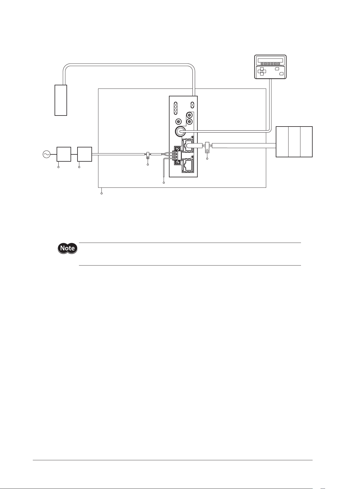
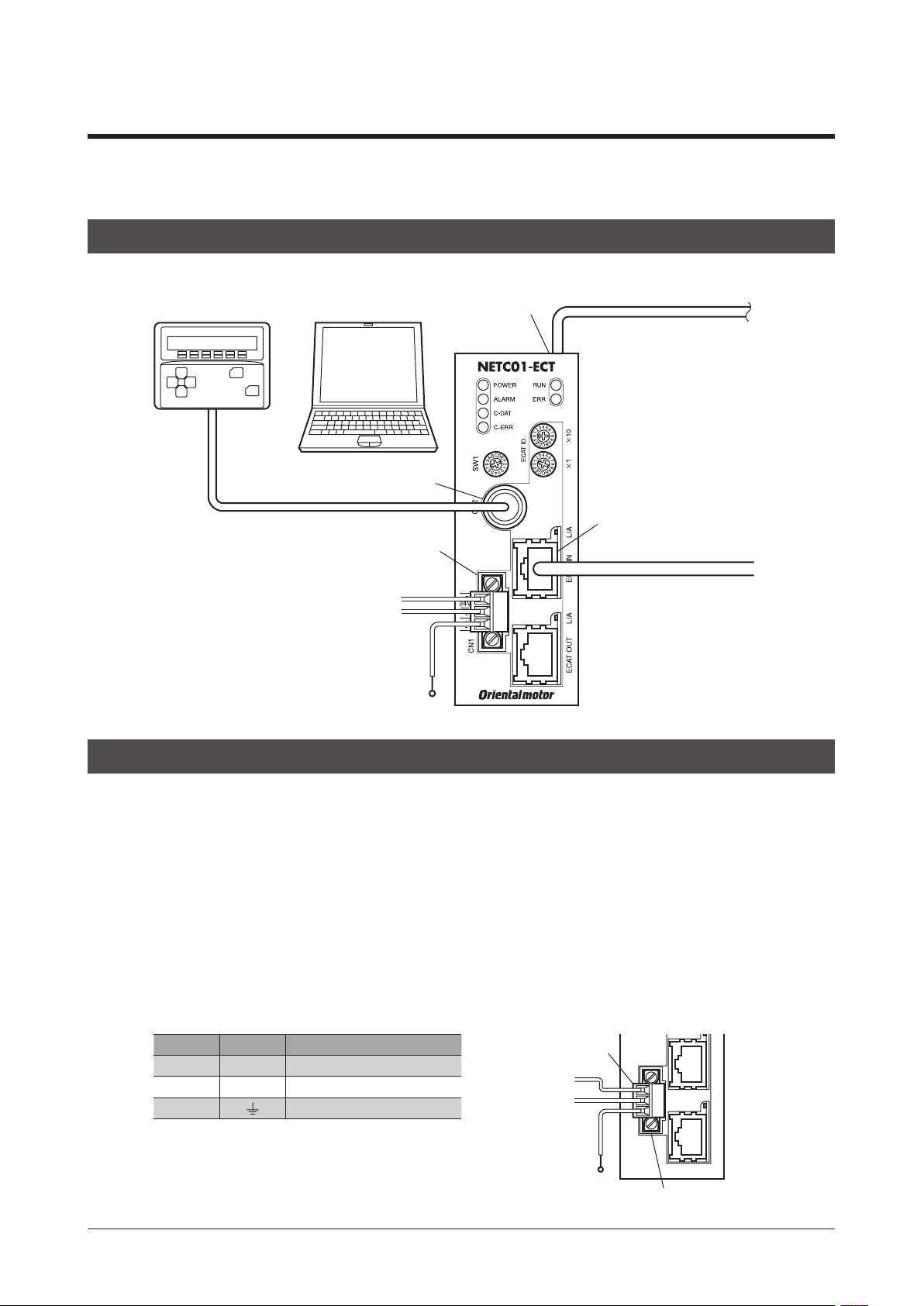
6-1 Connection example
OPX-2A MEXE02
Or
Data edit connector (CN2)
Power supply connector (CN1)
24 VDC
GND
NETC01-ECT
connector (CN6)
and power supply/communication cable, as well as the
RS-485 communication cable
ECAT IN
EtherCAT communication cable
FG
6-2 Connecting the power supply and grounding the
Connecting the power supply
Connect the power supply cable (AWG22: 0.3 mm2) to the power supply connector (CN1) of the
CN1 connector (3 pins).
Grounding the
Ground the Frame Ground terminal (FG) of the
Ground using a wire of AWG24 to 16 (0.2 to 1.25 mm2), and do not share the protective earth terminal with a welder or any other
power equipment.
CN1 connector pin assignments
Pin No. Name Description
1 + +24 VDC±10% 0.2 A or more
2
3
NETC01-ECT
Power supply GND
−
Frame Ground
NETC01-ECT
as necessary.
CN1 connector (supplied)
24 VDC
GND
NETC01-ECT
NETC01-ECT
using the supplied
FG
Power supply connector (CN1)
13
▐
Page 14
Connection
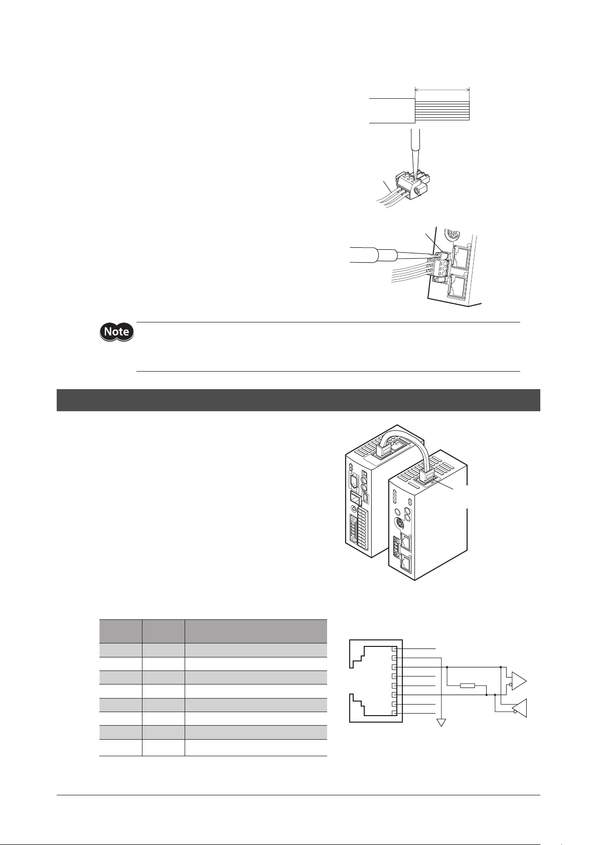
7 mm (0.28 in.)
Power supply input
Connecting method
1. Strip the insulation cover of the lead wire by 7 mm (0.28 in.)
2. Insert each lead wire into the CN1 connector and tighten the screw
using a screwdriver (connector screw size: M2).
Tightening torque: 0.22 to 0.25 N·m (31 to 35 oz-in)
Flap tip screwdriver
Lead wire
CN1 connector
3. Insert the CN1 connector into power supply connector (CN1) and
tighten the screws using a screwdriver (connector screw size: M2.5).
Tightening torque: 0.4 N·m (56 oz-in)
•When connecting, pay attention to the polarity of the power supply. Reverse-polarity connection may cause
damage to the
•Do not wire the power supply cable of the
so may cause malfunction due to noise.
NETC01-ECT
.
NETC01-ECT
in the same cable duct with other power lines. Doing
connector (CN1)
6-3 Connecting the RS-485 communication cable
Connect the
compatible product using the supplied RS-485
communication cable.
Connect the RS-485 communication cable to RS485 communication connector (CN6). Since RS-485
communication cables of two lengths are supplied, use
either one of the two.
You can also use a commercial LAN cable (shielded straight
cable) to link drivers.
NETC01-ECT
and RS-485 communication
RS-485 communication
connector (CN6)
14
▌
CN6 connector pin assignments
Pin No.
1 N.C. Not used (Do not connect anything.)
2 GND GND
3 TR+ RS-485 communication signal (+)
4 N.C. Not used
5 N.C. Not used
6 TR− RS-485 communication signal (−)
7 N.C. Not used
8 N.C. Not used
Signal
name
Description
RS-485 communication
compatible product
NETC01-ECT
•
* The GND line is used in common with CN1 (not insulated)
NETC01-ECT
internal circuit and termination resistor
1 N.C.
2 GND
3 TR+
4 N.C.
5 N.C.
6 TR
7 N.C.
8 N.C.
-
120 Ω
0 V *
Page 15

6-4 Connecting the EtherCAT communication cable
NETC01-ECT NETC01-ECT
Connection
Connect the master device and the ECAT IN on the
ECAT IN
EtherCAT
communication
cable *
ECAT OUT
Communication cannot be performed in a wrong connection. When connecting among the
be sure to connect from the ECAT OUT to the ECAT IN.
6-5 Connecting the data setter
Connect the
setting software to the data edit connector (CN2) on the
.
ECT
cable or communication cable for the data
OPX-2A
NETC01-ECT
* Keep the length of the EtherCAT communication cable to 100 m (330 ft.) or less.
NETC01-
using the EtherCAT communication cable.
Master device
ECAT IN
EtherCAT
communication
cable *
ECAT OUT
Data edit connector (CN2)
NETC01-ECT
units,
Cable for OPX-2A or communication
cable for the data setting software
The power supply connector (CN1), EtherCAT communication input port (ECAT IN), EtherCAT communication
output port (ECAT OUT), data edit connector (CN2) and RS-485 communication connector (CN6) of the
NETC01-ECT
do not connect any equipment (PC, etc.) whose negative terminal is grounded. Doing so may cause the
NETC01-ECT
are not electrically insulated. When grounding the positive terminal of the power supply,
and the equipment to short, damaging both.
15
▐
Page 16

Guidance
7 Guidance
If you are new to the
This chapter explains how to perform test operation via EtherCAT communication using the
Series built-in controller type as an example.
AZ
NETC01-ECT
, read this section to understand the operating methods along with the operation ow.
STEP1 Installation and connection
STEP2 Setting of
NETC01-ECT
Parameters are enabled after the power is cycled.
STEP3 Setting of driver
STEP4 Power cycle and check of LED
Parameters are enabled after the power is cycled.
STEP5 Operation of motor
zOperation condition
Here, the motor is supposed to be operated under the
following conditions.
NETC01-ECT
•
•Number of divers connected: One
•Driver address number: 0
•Driver termination resistor: Enabled
node address: 1
NETC01-ECT
in combination with the
•Before operating the motor, check the condition of the surrounding area to ensure safety.
•Before starting guidance, import the ESI le to the EtherCAT Conguration Tool of the PLC and register the PLC
conguration in advance. The ESI le can be downloaded from Oriental Motor Website Download Page.
The termination resistor for the
the termination resistor.
NETC01-ECT
is built into the product. This product can be used without setting
16
▌
Page 17
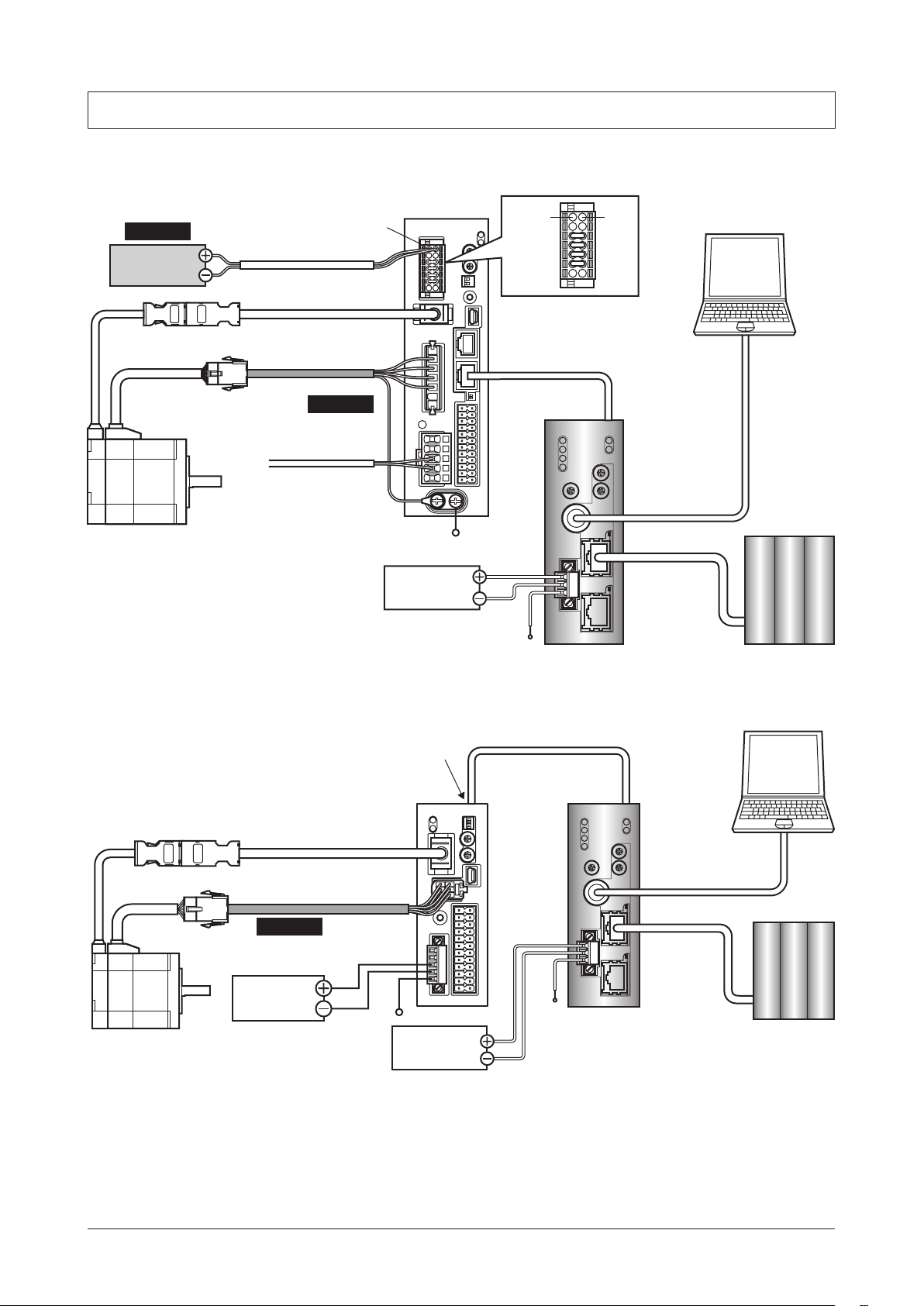
STEP 1 Check the installation and connection
AC power input driver
Guidance
*Necessary
24 VDC
power supply
CN1 connector
Connect to +24 V and 0 V
Connect to ENCODER
Cable for encoder
Connect to MOTOR
Cable for motor
*Necessary
Main power supply
Driver
PE
24 VDC
power supply
+24 V 0 V
Connect to CN6 or CN7
RS-485
communication
cable
FG
NETC01-ECT
Communication
cable for the data
setting software
Connect to CN2
EtherCAT
communication
cable
MEXE02 (PC)
Master device
DC power input driver
Cable for encoder
*Necessary
24 VDC
power supply
Connect to CN6 or CN7
Connect to CN3
Connect to CN2
Cable for motor
PE
24 VDC
power supply
RS-485 communication cable
Driver
FG
NETC01-ECT
Communication
cable for the data
setting software
Connect to CN2
EtherCAT
communication
cable
MEXE02 (PC)
Master device
17
▐
Page 18

Guidance
STEP 2 Set the parameters and switches of the
Set the parameters and switches of the
1. Turn on the power to the
At this time, since parameters and switches are not set, the ALARM LED will be lit.
Move on the next procedure, and set parameters and switches.
2. Start the
Select the
MEXE02
NETC01-ECT
NETC01-ECT
and set the parameters.
.
NETC01-ECT
.
.
NETC01-ECT
3. Set the "Connection (axis #)" parameter of the driver connected to the
The initial value in the "Connection (axis #0)" parameter is set to "Enable." When the connected driver is 1 unit and the address
number of the driver is "0," it is not required to set the "Connection (axis #)" parameter.
MEXE02
tree view Parameter name Description Initial value
Connection (axis #0) Enables the address number of the driver
connected to the
Setting range
Disable
Enable
System
Connection (axis #1)
to
Connection (axis #15)
NETC01-ECT
The initial value is "Enable."
NETC01-ECT
to "Enable" using the
.
Enable
Disable
MEXE02
.
18
▌
Page 19
Guidance
AC input driver
DC input driver
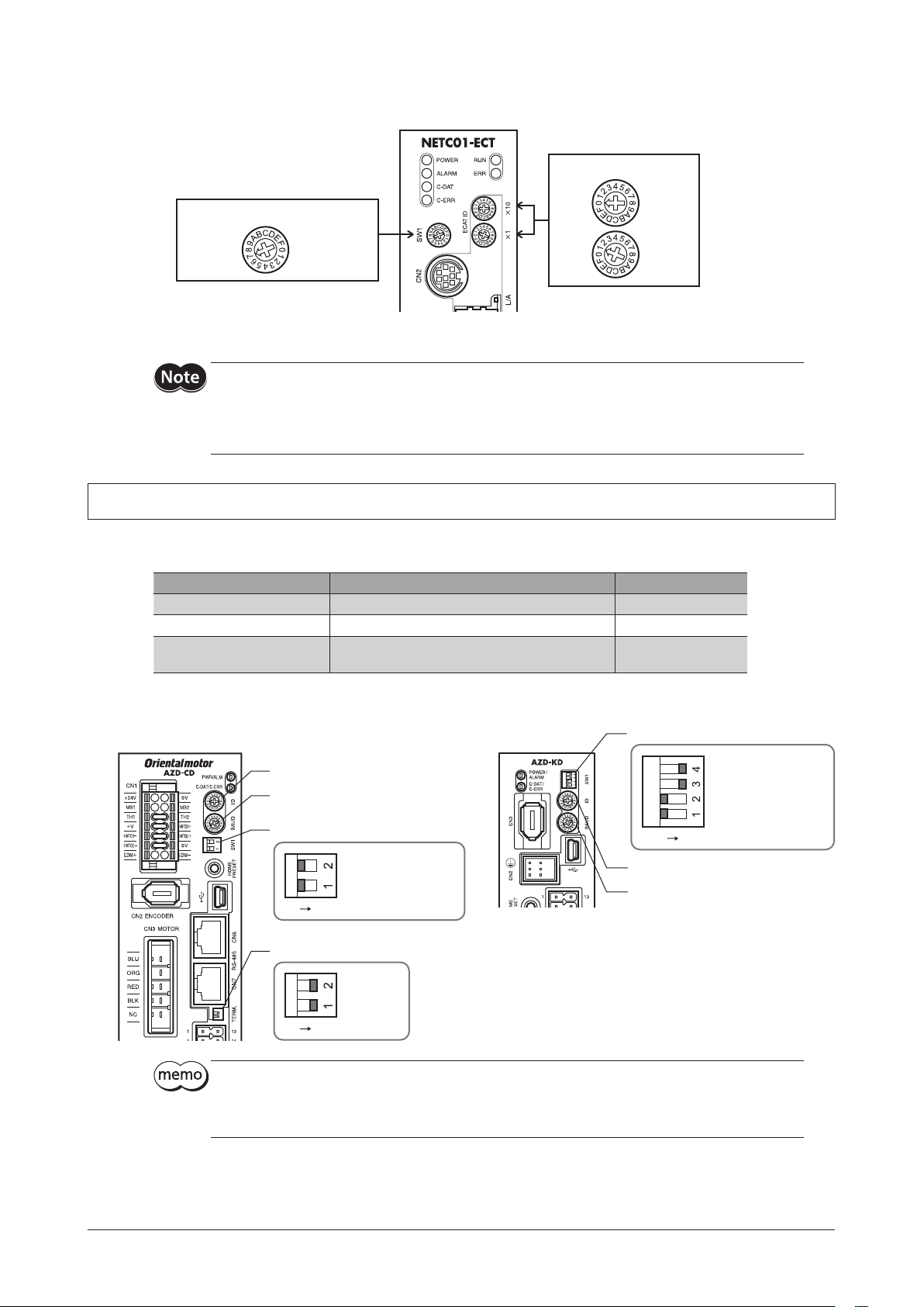
4. Set the switches of the
Set as the illustration below.
RS-485 transmission rate: 625 kbps
5. Turn o the
NETC01-ECT
•When multiple drivers are connected, set connection parameters as many as the drivers.
•To activate the changed "Connection (address number)" parameter, cycling the power supply is required.
•For the SW1, always set to "7." If the switch is set to the dial of "8" or higher, the communication switch setting
error alarm will be generated when turning on the power. And do not set the switch to the dial of "0" to "6"
because they cannot be used. (An alarm will not be generated.)
NETC01-ECT.
SW1: 7
power.
STEP 3 Set the switches of the driver
Set the following with the switches of the driver. For the protocol, select "OFF" (network converter).
The status becomes as shown in the following gures after setting.
EtherCAT node address: 1
×10: 0
×1: 1
Setting contents Switch Factory setting
Protocol: Network converter Turn No.2 of SW1 OFF OFF
Address number: 0 Turn No.1 of SW1 OFF, set ID to 0 No.1: OFF, ID: 0
Termination resistor: ON
AC power input driver: Turn Nos.1 and 2 of TERM ON
DC power input driver: Turn Nos.3 and 4 of SW1 ON
OFF
Function setting switch (SW1)
Address number setting switch (ID)
Transmission rate setting switch
(BAUD)
Function setting switch (SW1)
No.2: Protocol
No.1: Address number
ON
Termination resistor setting switch
(TERM.)
Address number setting switch (ID)
Transmission rate setting switch
(BAUD)
ON
No.2: ON
No.1: ON
ON
No.3, No.4: Termination
resistor
No.2: Protocol
No.1: Address number
•For the address number, set the one with the "Connection (address number)" parameter of the
set to "Enable."
•For the AZ Series, the transmission rate does not require to set. It is xed to 625,000 bps in the
"Baudrate(GWv2)" parameter. The BAUD switch can point anywhere.
NETC01-ECT
19
▐
Page 20

Guidance
NETC01-ECT
AC input driver
DC input driver
STEP 4 Cycle the power and check the LED
Check that the LED of the driver and
NETC01-ECT
are as shown in the gure.
Green lit
Green lit
•When the C-DAT/C-ERR LED (red) of the driver or the C-ERR LED (red) of the
Check the transmission rate of RS-485 communication or the address number.
•When the ERR LED (red) of the
content.
NETC01-ECT
is blink: An EtherCAT communication error has been occurred. Check the error
Perform continuous operation via remote I/O of EtherCAT
STEP 5
communication
OFF
Green lit
OFF
NETC01-ECT
Green litGreen lit
OFF
Green blinking
is lit:
CoE Index
2600h
Turn FW-POS of the address number 0 ON with the remote I/O of EtherCAT communication. Continuous operation for the operation
data No.0 is started at the 1000 Hz of starting speed.
Initial values of the remote I/O are as follows.
zMaster to
Sub-
index
0
1
2
NETC01-ECT
Name Type Access Description
−
I/O
Command
(lower)
I/O
Command
(upper)
U8 R Number of Sub-index: 2
bit[7] bit[6] bit[5] bit[4] bit[3] bit[2] bit[1] bit[0]
U8 RW
U8 RW
NET-IN7 NET-IN6 NET-IN5 NET-IN4 NET-IN3 NET-IN2 NET-IN1 NET-IN0
ALM-RST FREE STOP ZHOME START M2 M1 M0
bit[7] bit[6] bit[5] bit[4] bit[3] bit[2] bit[1] bit[0]
NET-IN15 NET-IN14 NET-IN13 NET-IN12 NET-IN11 NET-IN10 NET-IN9 NET-IN8
RV-POS FW-POS RV-JOG-P FW-JOG-P SSTART D-SEL2 D-SEL1 D-SEL0
STEP 6 Were you able to operate the motor properly?
How did it go? Were you able to operate the motor properly? If the motor does not function, check the following points:
•Is an alarm generated in the driver or
•Are the power supply, motor, and RS-485 communication cable connected securely?
•Are the protocol, address number, transmission rate and termination resistor set correctly?
•Is the "connection (address number)" parameter of the
•Is the C-DAT LED of
•Is the ERR LED of
•Is the L/A LED of
Is the motor excited, or is the setting of the excitation method correct?
•Are the parameters of the driver set correctly?
•Is the operation stop signal input to the driver?
NETC01-ECT
NETC01-ECT
NETC01-ECT
NETC01-ECT
turned o? Or is the C-ERR LED lit in red? (A RS-485 communication error has been occurred.)
blinks in red? (An EtherCAT communication error has been occurred. _p.41)
turnde o? Or is it blinks in green? (An EtherCAT communication error has been occurred. _p.41)
?
NETC01-ECT
set correctly?
20
▌
Page 21

8 Setting
Setting
This chapter explains how to set the functions of the
Be sure to turn o the
still on, the new switch settings will not become eective until the
RS-485 communication
transmission rate
setting switch (SW1)
NETC01-ECT
NETC01-ECT
power before setting the switches. If the switches are set while the power is
.
NETC01-ECT
Node address setting switch
(ECAT ID ×1, ×10)
8-1 Transmission rate of RS-485 communication
Set the transmission rate using the RS-485 communication transmission rate setting switch (SW1).
Factory setting 7 (625 kbps)
For the SW1, always set to "7." If the switch is set to the dial of "8" or higher, the communication switch setting
error alarm will be generated when turning on the power. And do not set the switch to the dial of "0" to "6"
because they cannot be used. (An alarm will not be generated.)
power is cycled.
8-2 Node address of EtherCAT
Set the node address of the
When connecting two or more EtherCAT compatible products, do not set duplicate node address.
Set the upper using the "ECAT ID ×10" and the lower using the "ECAT ID ×1."
NETC01-ECT
Setting range 0 to 255 (00h to FFh)
Factory setting 1 (×10: 0, ×1: 1)
using the two node address setting switches (ECAT ID ×1 and ×10).
21
▐
Page 22

Basic function
9 Basic function
This chapter explains the basic function and signals of the
9-1 Remote I/O list
The PDO mapping is possible for remote I/O. 16 axes of connectable units are assigned.
•Remote I/O status ................................. Mapping to TxPDO is possible.
•Remote I/O command......................... Mapping to RxPDO is possible.
CoE Index Name CoE Index Name
Axis No.
Axis 0 2400h Remote I/O Status (Axis 0) 2600h Remote I/O Command (Axis 0)
Axis 1 2401h Remote I/O Status (Axis 1) 2601h Remote I/O Command (Axis 1)
Axis 2 2402h Remote I/O Status (Axis 2) 2602h Remote I/O Command (Axis 2)
Axis 3 2403h Remote I/O Status (Axis 3) 2603h Remote I/O Command (Axis 3)
Axis 4 2404h Remote I/O Status (Axis 4) 2604h Remote I/O Command (Axis 4)
Axis 5 2405h Remote I/O Status (Axis 5) 2605h Remote I/O Command (Axis 5)
Axis 6 2406h Remote I/O Status (Axis 6) 2606h Remote I/O Command (Axis 6)
Axis 7 2407h Remote I/O Status (Axis 7) 2607h Remote I/O Command (Axis 7)
Axis 8 2408h Remote I/O Status (Axis 8) 2608h Remote I/O Command (Axis 8)
Axis 9 2409h Remote I/O Status (Axis 9) 2609h Remote I/O Command (Axis 9)
Axis 10 240Ah Remote I/O Status (Axis 10) 260Ah Remote I/O Command (Axis 10)
Axis 11 240Bh Remote I/O Status (Axis 11) 260Bh Remote I/O Command (Axis 11)
Axis 12 240Ch Remote I/O Status (Axis 12) 260Ch Remote I/O Command (Axis 12)
Axis 13 240Dh Remote I/O Status (Axis 13) 260Dh Remote I/O Command (Axis 13)
Axis 14 240Eh Remote I/O Status (Axis 14) 260Eh Remote I/O Command (Axis 14)
Axis 15 240Fh Remote I/O Status (Axis 15) 260Fh Remote I/O Command (Axis 15)
Response
(
NETC01-ECT
to master)
Remote I/O status
NETC01-ECT
.
Command
(Master to
NETC01-ECT
Remote I/O command
)
Remote I/O status
zStatus [
CoE Index
2400h
(2400h
to
240Fh)
NETC01-ECT
Sub-
index
0
I/O Status
1
I/O Status
2
to master]
Name Type Access Description
−
(lower)
(upper)
U8 R Number of Sub-index: 2
bit[7] bit[6] bit[5] bit[4] bit[3] bit[2] bit[1] bit[0]
U8 R
U8 R
NET-
OUT7
bit[7] bit[6] bit[5] bit[4] bit[3] bit[2] bit[1] bit[0]
NET-
OUT15
NET-
OUT6
NET-
OUT14
NET-
OUT5
NET-
OUT13
NET-
OUT4
NET-
OUT12
NET-
OUT3
NET-
OUT11
NET-
OUT2
NET-
OUT10
NET-
OUT1
NET-
OUT9
NET-
OUT0
NET-
OUT8
22
▌
Page 23

Remote I/O command
Basic function
zCommand [master to
CoE Index
2600h
(2600h
to
260Fh)
Sub-
index
0
1
2
NETC01-ECT
Name Type Access Description
−
I/O Command
(lower)
I/O Command
(upper)
U8 R Number of Sub-index: 2
U8 RW
U8 RW
]
bit[7] bit[6] bit[5] bit[4] bit[3] bit[2] bit[1] bit[0]
NET-IN7 NET-IN6 NET-IN5 NET-IN4 NET-IN3 NET-IN2 NET-IN1 NET-IN0
bit[7] bit[6] bit[5] bit[4] bit[3] bit[2] bit[1] bit[0]
NET-IN15 NET-IN14 NET-IN13 NET-IN12 NET-IN11 NET-IN10 NET-IN9 NET-IN8
For remote I/O assignment of the RS-485 communication compatible product, check the USER MANUAL or
OPERATING MANUAL Function Edition of each product.
9-2 Remote register list
Remote register is for PDO mapping.
•Remote register command ........................Mapping to RxPDO is possible.
•Remote register response ...........................Mapping to TxPDO is possible.
With remote register, read/write for parameters of the RS-485 communication compatible product that is connected to the
NETC01-ECT
Axis No.
Axis 0 2800h Remote Register Command (Axis 0) 2900h Remote Register Response (Axis 0)
Axis 1 2801h Remote Register Command (Axis 1) 2901h Remote Register Response (Axis 1)
Axis 2 2802h Remote Register Command (Axis 2) 2902h Remote Register Response (Axis 2)
Axis 3 2803h Remote Register Command (Axis 3) 2903h Remote Register Response (Axis 3)
Axis 4 2804h Remote Register Command (Axis 4) 2904h Remote Register Response (Axis 4)
Axis 5 2805h Remote Register Command (Axis 5) 2905h Remote Register Response (Axis 5)
Axis 6 2806h Remote Register Command (Axis 6) 2906h Remote Register Response (Axis 6)
Axis 7 2807h Remote Register Command (Axis 7) 2907h Remote Register Response (Axis 7)
Axis 8 2808h Remote Register Command (Axis 8) 2908h Remote Register Response (Axis 8)
Axis 9 2809h Remote Register Command (Axis 9) 2909h Remote Register Response (Axis 9)
Axis 10 280Ah Remote Register Command (Axis 10) 290Ah Remote Register Response (Axis 10)
Axis 11 280Bh Remote Register Command (Axis 11) 290Bh Remote Register Response (Axis 11)
Axis 12 280Ch Remote Register Command (Axis 12) 290Ch Remote Register Response (Axis 12)
Axis 13 280Dh Remote Register Command (Axis 13) 290Dh Remote Register Response (Axis 13)
Axis 14 280Eh Remote Register Command (Axis 14) 290Eh Remote Register Response (Axis 14)
Axis 15 280Fh Remote Register Command (Axis 15) 290Fh Remote Register Response (Axis 15)
, maintenance command, and monitor can be performed.
CoE Index Name CoE Index Name
Command
(Master to
NETC01-ECT
Remote register command
)
Response
(
NETC01-ECT
to master)
Remote register response
23
▐
Page 24

Basic function
Remote register command
zCommand [master to
CoE Index
2800h
(2800h
to
280Fh)
zDescription of TRIG
Name Description Setting range
TRIG
Remote register response
zResponse [
CoE Index
2900h
(2900h
to
290Fh)
Sub-
index
0
1 Axis U8 R Reserved (not used)
2 Command U16 R Command code response
3 Data INT32 R Data response
4 Status U8 R
NETC01-ECT
Sub-
index
0
1 Axis U8 RW Reserved (not used)
2 Command U16 RW Command code
3 Data INT32 RW Data
4 TRIG U8 RW
This is a trigger to execute a command code.
When TRIG is changed from 0 to 1, the command code is executed.
NETC01-ECT
Name Type Access Description
−
Name Type Access Description
−
to master]
U8 R Number of Sub-index: 4
]
U8 R Number of Sub-index: 4
bit[7] bit[6] bit[5] bit[4] bit[3] bit[2] bit[1] bit[0]
− − − −
0: No action
1: Execute
bit[7] bit[6] bit[5] bit[4] bit[3] bit[2] bit[1] bit[0]
− −
− −
Command Error Axis Error STATUS TRIG_R
− − −
TRIG
zDescription of Status
Name Description Setting range
TRIG_R Indicates a response to the TRIG of the remote register command.
STATUS Detects an error when writing.
Axis Error Indicates an error of the address number.
Command Error Indicates an error of the command code. Reserved (0 xed)
0: TRIG undetected
1: TRIG detected
0: Normal
1: Error
0: Normal
1: Error
24
▌
Page 25

Basic function
Timing chart
zRead (normal time)
This explains how to read the position (travel amount) of the operation data No.0 using the AR Series.
1. Check the TRIG response (TRIG_R) is OFF.
2. Set the command code "0200h" of the position (travel amount) of the operation data No.0 to the command code (Command).
3. Turn the transmission request (TRIG) ON.
4. The TRIG response (TRIG_R) is turned ON, and the position (travel amount) of the operation data No.0 is returned to the data
response (Data).
If the command code is read properly, the transmission error (STATUS) remains OFF.
5. Check the TRIG response (TRIG_R) has been turned ON and turn the transmission request (TRIG) OFF.
6. The TRIG response (TRIG_R) is turned OFF.
Continuously, the following command code can be read. The command code "0240h" of the speed of the operation data No.0 is
read in the timing chart below.
Remote
register
CoE
Index
2800h
Command
(address
number 0)
Sub-
index
2
4
4 (bit0)
Description
Command code (Command)
Transmission request (TRIG)
TRIG response (TRIG_R)
ON
OFF
ON
OFF
Timing chart
2
0200h 0240h
3
5
641
2900h
Response
(address
Data response (Data)
3
1000 3000
number 0)
4 (bit1)
Transmission error (STATUS)
ON
OFF
zRead (error)
This explains the case that the undened command code was read using the AR Series.
1. Check the TRIG response (TRIG_R) is OFF.
2. Set the undened command code "0001h" to the command code (Command).
3. Turn the transmission request (TRIG) ON.
4. The TRIG response (TRIG_R) is turned ON.
At this time, since the undened command code has been set, the transmission error (STATUS) is turned ON.
The data in error is read because the transmission error was generated.
5. Turn the transmission request (TRIG) OFF in order to release the transmission error (STATUS).
The TRIG response (TRIG_R) and transmission error (STATUS) are turned OFF.
Remote
register
Command
CoE
Index
2800h
(address
number 0)
Sub-
index
2
4
4 (bit0)
Description
Command code (Command)
Transmission request (TRIG)
TRIG response (TRIG_R)
ON
OFF
ON
OFF
Timing chart
2
0001h
3 5
1 4
2900h
Response
(address
Data response (Data)
3
xxxxxxx
number 0)
4 (bit1)
Transmission error (STATUS)
ON
OFF
25
▐
Page 26

Basic function
zWrite (normal time)
This explains how to write the position (travel amount) to the operation data No.0 using the AR Series.
1. Check the TRIG response (TRIG_R) is OFF.
2. Set the command code "1200h" of the position (travel amount) of the operation data No.0 to the command code (Command).
3. Set the position (travel amount) "1000 pulses" to the data (Data).
4. Turn the transmission request (TRIG) ON.
5. The TRIG response (TRIG_R) is turned ON.
If the command code is written properly, the transmission error (STATUS) remains OFF.
6. Check the TRIG response (TRIG_R) has been turned ON and turn the transmission request (TRIG) OFF.
7. The TRIG response (TRIG_R) is turned OFF.
Continuously, the following command code can be written. The command code "1240h" of the speed of the operation data No.0
is written in the timing chart below.
Remote
register
Command
Response
CoE
Index
2800h
(address
number 0)
2900h
(address
number 0)
Sub-
index
2
3
4
4 (bit0)
4 (bit1)
Description
Command code (Command)
Data
Transmission request (TRIG)
TRIG response (TRIG_R)
Transmission error (STATUS)
ON
OFF
ON
OFF
ON
OFF
2
3
4
1 5
Timing chart
1200h 1240h
1000 3000
6
7
zWrite (error)
This explains the case that the position (travel amount) that is out of the setting range was written using the AR Series.
The range of the position (travel amount) of the operation data for the AR Series is −8,388,608 to +8,388,607.
1. Check the TRIG response (TRIG_R) is OFF.
2. Set the command code "1200h" of the position (travel amount) of the operation data No.0 to the command code (Command).
3. Set the position (travel amount) "9,999,999 pulses" that is out of the setting range to the data (Data).
4. Turn the transmission request (TRIG) ON.
5. The TRIG response (TRIG_R) is turned ON.
At this time, since the position (travel amount) that is out of the setting range has been set, the transmission error (STATUS) is
turned ON.
The position (travel amount) is not written because the transmission error was generated.
6. Turn the transmission request (TRIG) OFF in order to release the transmission error (STATUS).
The TRIG response (TRIG_R) and transmission error (STATUS) are turned OFF.
Remote
register
Command
Response
26
▌
CoE
Index
2800h
(address
number 0)
2900h
(address
number 0)
Sub-
index
2
3
4
4 (bit0)
4 (bit1)
Description
Command code (Command)
Data
Transmission request (TRIG)
TRIG response (TRIG_R)
Transmission error (STATUS)
ON
OFF
ON
OFF
ON
OFF
Timing chart
2
1200h
3
9,999,999
4 6
1 5
Page 27

9-3 Remote monitor list
Remote monitor is an area for PDO mapping.
•Remote monitor command .......................Mapping to RxPDO is possible.
•Remote monitor response ..........................Mapping to TxPDO is possible.
Since 16 dedicated objects for monitor are provided, multiple monitors to one axis can be performed simultaneously.
Refer to the following table for the CoE Index of the object area.
CoE Index Name CoE Index Name
Area
Monitor 0 2A00h Remote Monitor 0 Command 2B00h Remote Monitor 0 Response
Monitor 1 2A01h Remote Monitor 1 Command 2B01h Remote Monitor 1 Response
Monitor 2 2A02h Remote Monitor 2 Command 2B02h Remote Monitor 2 Response
Monitor 3 2A03h Remote Monitor 3 Command 2B03h Remote Monitor 3 Response
Monitor 4 2A04h Remote Monitor 4 Command 2B04h Remote Monitor 4 Response
Monitor 5 2A05h Remote Monitor 5 Command 2B05h Remote Monitor 5 Response
Monitor 6 2A06h Remote Monitor 6 Command 2B06h Remote Monitor 6 Response
Monitor 7 2A07h Remote Monitor 7 Command 2B07h Remote Monitor 7 Response
Monitor 8 2A08h Remote Monitor 8 Command 2B08h Remote Monitor 8 Response
Monitor 9 2A09h Remote Monitor 9 Command 2B09h Remote Monitor 9 Response
Monitor 10 2A0Ah Remote Monitor 10 Command 2B0Ah Remote Monitor 10 Response
Monitor 11 2A0Bh Remote Monitor 11 Command 2B0Bh Remote Monitor 11 Response
Monitor 12 2A0Ch Remote Monitor 12 Command 2B0Ch Remote Monitor 12 Response
Monitor 13 2A0Dh Remote Monitor 13 Command 2B0Dh Remote Monitor 13 Response
Monitor 14 2A0Eh Remote Monitor 14 Command 2B0Eh Remote Monitor 14 Response
Monitor 15 2A0Fh Remote Monitor 15 Command 2B0Fh Remote Monitor 15 Response
Command
(master to
NETC01-ECT
Remote monitor command
)
Response
(
NETC01-ECT
to master)
Remote monitor response
Basic function
Remote monitor command
zCommand [master to
CoE Index
2A00h
(2A00h
to
2A0Fh)
Sub-
index
0
1 Axis U8 RW Address number
2 Command U16 RW Command code
3 Data INT32 RW Reserved (not used)
4 TRIG U8 RW
NETC01-ECT
Name Type Access Description
−
zDescription of TRIG
Name Description Setting range
TRIG
This is a trigger to execute the command code of monitor.
When TRIG is changed from 0 to 1, the command code is executed.
]
U8 R Number of Sub-index: 4
bit[7] bit[6] bit[5] bit[4] bit[3] bit[2] bit[1] bit[0]
− − − − − − −
0: No action
1: Execute
TRIG
27
▐
Page 28

Basic function
Remote monitor response
CoE Index
2B00h
(2B00h
to
2B0Fh)
zResponse [
Sub-
index
0
1 Axis U8 R Address number response
2 Command U16 R Command code response
3 Data INT32 R Monitor data
4 Status U8 R
NETC01-ECT
Name Type Access Description
−
to master]
U8 R Number of Sub-index: 4
bit[7] bit[6] bit[5] bit[4] bit[3] bit[2] bit[1] bit[0]
− − − −
Command Error Axis Error STATUS TRIG_R
zDescription of Status
Name Description Setting range
TRIG_R Indicates a response to the TRIG of the remote monitor command.
STATUS Detects an error when writing.
Axis Error Indicates an error of the address number.
Command Error
Indicates an error of the command code of monitor.
Evaluates as an error if the command code other than monitor was input.
Timing chart
0: TRIG undetected
1: TRIG detected
0: Normal
1: Error
0: Normal
1: Error
0: Normal
1: Error
zMonitor (normal time)
This explains how to monitor the command position of the driver for the address number 2 using the AR Series.
The monitor 0 is used for the monitor number.
1. Check the TRIG response (TRIG_R) is OFF.
2. Set the address number "2" of the driver to the address number (Axis).
3. Set the command code "2063h" of the command position to the command code (Command).
4. Turn the monitor request (TRIG) ON.
The monitor is continued while the monitor request (TRIG) is being ON.
5. The TRIG response (TRIG_R) is turned ON, and the monitor value is returned to the monitor value (Data).
At this time, if the command code has been read properly, the transmission error (STATUS) remains OFF.
6. Turn the monitor request (TRIG) OFF.
The TRIG response (TRIG_R) is turned OFF, and the monitor is stopped.
Remote
monitor
Command
CoE
Index
2A00h
(monitor 0)
Sub-
index
1
2
4 (bit0)
4 (bit0)
Description
Address number (Axis)
Command code (Command)
Monitor request (TRIG)
TRIG response (TRIG_R)
ON
OFF
ON
OFF
2
3
4
1 5
Timing chart
2 (dec)
2063h
6
Monitor value (Data)
Response
28
▌
2B00h
(monitor 0)
4 (bit1) Transmission error (STATUS)
4 (bit2)
Address number error
(Axis Error)
ON
OFF
ON
OFF
3
100 101 102 103 104
Page 29

zMonitor (error)
This explains the case that the command code was set to the driver that is not connected using the AR Series.
The monitor 0 is used for the monitor number.
1. Check the TRIG response (TRIG_R) is OFF.
2. Set the address number "5" of the driver that is not connected to the address number (Axis).
3. Set the command code "2063h" of the command position to the command code (Command).
4. Turn the monitor request (TRIG) ON.
5. The TRIG response (TRIG_R) is turned ON.
At this time, since the address number of the driver that is not connected has been set, the transmission error (STATUS) and
address number error (Axis Error) are turned ON.
Since the monitor error is generated, the monitor is not performed properly.
6. Turn the monitor request (TRIG) OFF in order to release the transmission error (STATUS).
TRIG response (TRIG_R), transmission error (STATUS), and address number error (Axis Error) are turned OFF.
Basic function
Remote
monitor
Command
Response
CoE
Index
2A00h
(monitor 0)
2B00h
(monitor 0)
Sub-
index
1
2
4 (bit0)
4 (bit0)
3
Description
Address number (Axis)
Command code (Command)
Monitor request (TRIG)
TRIG response (TRIG_R)
Monitor value (Data)
4 (bit1) Transmission error (STATUS)
4 (bit2)
Address number error
(Axis Error)
ON
OFF
ON
1 5
OFF
ON
OFF
ON
OFF
Timing chart
2
5 (dec)
3
2063h
4
6
xxxxxxx
29
▐
Page 30

Basic function
9-4 Objects of the
Object lists of parameters, monitor, and maintenance for the
NETC01-ECT
Parameter
CoE Index Sub-index Type Access
2CC4h 0
2D80h 0
2D81h 0
2D82h 0
2D83h 0
2D84h 0
2D85h 0
2D86h 0
2D87h 0
2D88h 0
2D89h 0
2D8Ah 0
2D8Bh 0
2D8Ch 0
2D8Dh 0
2D8Eh 0
2D8Fh 0
U8 RW Possible
PDO possible/
not possible
NETC01-ECT
Parameter name Setting range
Data setter edit
(address number 0)
(address number 1)
(address number 2)
(address number 3)
(address number 4)
(address number 5)
(address number 6)
(address number 7)
(address number 8)
(address number 9)
(address number 10)
(address number 11)
(address number 12)
(address number 13)
(address number 14)
(address number 15)
are as follows.
Connection
Connection
Connection
Connection
Connection
Connection
Connection
Connection
Connection
Connection
Connection
Connection
Connection
Connection
Connection
Connection
0: Disable
1: Enable
Initial
value
1 A
1 B
0 B
0 B
0 B
0 B
0 B
0 B
0 B
0 B
0 B
0 B
0 B
0 B
0 B
0 B
0 B
Eective *
* A: Eective immediately, B: Eective after turning the power ON again
If the parameters that enters "B (Eective after turning the power ON again)" in the column of eective are
changed, cycle the power of the
maintenance command.
30
▌
NETC01-ECT
after executing "Batch non-volatile memory write (3E85h)" of the
Page 31

Monitor command
Basic function
CoE Index Sub-index Type Access
3E00h 0 U8 R Tx possible Present alarm
3E01h 0 U8 R Tx possible Alarm record 1
3E02h 0 U8 R Tx possible Alarm record 2
3E03h 0 U8 R Tx possible Alarm record 3
3E04h 0 U8 R Tx possible Alarm record 4
3E05h 0 U8 R Tx possible Alarm record 5
3E06h 0 U8 R Tx possible Alarm record 6
3E07h 0 U8 R Tx possible Alarm record 7
3E08h 0 U8 R Tx possible Alarm record 8
3E09h 0 U8 R Tx possible Alarm record 9
3E0Ah 0 U8 R Tx possible Alarm record 10
3E0Bh 0 U8 R Tx possible Present warning
3E0Ch 0 U8 R Tx possible Warning record 1
3E0Dh 0 U8 R Tx possible Warning record 2
3E0Eh 0 U8 R Tx possible Warning record 3
3E0Fh 0 U8 R Tx possible Warning record 4
3E10h 0 U8 R Tx possible Warning record 5
3E11h 0 U8 R Tx possible Warning record 6
3E12h 0 U8 R Tx possible Warning record 7
3E13h 0 U8 R Tx possible Warning record 8
3E14h 0 U8 R Tx possible Warning record 9
3E15h 0 U8 R Tx possible Warning record 10
3E30h *1 0 U8 R Tx possible Converter status
3E3Bh 0 U16 R Tx possible RS-485 communication scantime
3E3Ch *2 0 U16 R Tx possible RS-485 communication connection request
3E3Dh *3 0 U16 R Tx possible RS-485 communication connection response
3E40h 0 U8 R Tx possible Communication error (remote monitor 0)
3E41h 0 U8 R Tx possible Communication error (remote monitor 1)
3E42h 0 U8 R Tx possible Communication error (remote monitor 2)
3E43h 0 U8 R Tx possible Communication error (remote monitor 3)
3E44h 0 U8 R Tx possible Communication error (remote monitor 4)
3E45h 0 U8 R Tx possible Communication error (remote monitor 5)
3E46h 0 U8 R Tx possible Communication error (remote monitor 6)
3E47h 0 U8 R Tx possible Communication error (remote monitor 7)
3E48h 0 U8 R Tx possible Communication error (remote monitor 8)
3E49h 0 U8 R Tx possible Communication error (remote monitor 9)
3E4Ah 0 U8 R Tx possible Communication error (remote monitor 10)
3E4Bh 0 U8 R Tx possible Communication error (remote monitor 11)
3E4Ch 0 U8 R Tx possible Communication error (remote monitor 12)
3E4Dh 0 U8 R Tx possible Communication error (remote monitor 13)
3E4Eh 0 U8 R Tx possible Communication error (remote monitor 14)
3E4Fh 0 U8 R Tx possible Communication error (remote monitor 15)
3E50h 0 U8 R Tx possible Communication error (remote register 0)
3E51h 0 U8 R Tx possible Communication error (remote register 1)
3E52h 0 U8 R Tx possible Communication error (remote register 2)
3E53h 0 U8 R Tx possible Communication error (remote register 3)
3E54h 0 U8 R Tx possible Communication error (remote register 4)
3E55h 0 U8 R Tx possible Communication error (remote register 5)
3E56h 0 U8 R Tx possible Communication error (remote register 6)
PDO possible/
not possible
Parameter name
31
▐
Page 32

Basic function
CoE Index Sub-index Type Access
3E57h 0 U8 R Tx possible Communication error (remote register 7)
3E58h 0 U8 R Tx possible Communication error (remote register 8)
3E59h 0 U8 R Tx possible Communication error (remote register 9)
3E5Ah 0 U8 R Tx possible Communication error (remote register 10)
3E5Bh 0 U8 R Tx possible Communication error (remote register 11)
3E5Ch 0 U8 R Tx possible Communication error (remote register 12)
3E5Dh 0 U8 R Tx possible Communication error (remote register 13)
3E5Eh 0 U8 R Tx possible Communication error (remote register 14)
3E5Fh 0 U8 R Tx possible Communication error (remote register 15)
*1 CoE Index: 3E30h (Converter stetus)
The status of the
CoE
Index
3E30h 0 U8 R
*2 CoE Index: 3E3Ch (RS-485 communication connection request)
The setting status of the "Connection (address number)" parameter can be monitored.
CoE
Index
3E3Ch 0 U16 R
Sub-
index
Sub-
index
NETC01-ECT
Type Access Description
Type Access Description
can be monitored.
bit[7] bit[6] bit[5] bit[4] bit[3] bit[2] bit[1] bit[0]
− − − − −
bit[7] bit[6] bit[5] bit[4] bit[3] bit[2] bit[1] bit[0]
Axis 7 Axis 6 Axis 5 Axis 4 Axis 3 Axis 2 Axis 1 Axis 0
bit[15] bit[14] bit[13] bit[12] bit[11] bit[10] bit[9] bit[8]
Axis 15 Axis 14 Axis 13 Axis 12 Axis 11 Axis 10 Axis 9 Axis 8
PDO possible/
not possible
Parameter name
S-BSY WNG ALM
*3 CoE Index: 3E3Dh (RS-485 communication connection response)
The communication status of RS-485 communication can be monitored.
CoE
Index
3E3Dh 0 U16 R
Sub-
index
Type Access Description
bit[7] bit[6] bit[5] bit[4] bit[3] bit[2] bit[1] bit[0]
Axis 7 Axis 6 Axis 5 Axis 4 Axis 3 Axis 2 Axis 1 Axis 0
bit[15] bit[14] bit[13] bit[12] bit[11] bit[10] bit[9] bit[8]
Axis 15 Axis 14 Axis 13 Axis 12 Axis 11 Axis 10 Axis 9 Axis 8
1: Communicating properly
0: Communication error, or the "connection (address number)" parameter is set to
"Disable."
zAlarm code list
Code Name Description
00h Alarm not present
47h EEPROM error The stored data in the
83h Communication switch setting error Transmission rate setting switch was out of the specication.
84h RS-485 communication error The RS-485 communication error has been detected three times consecutively.
F0h CPU error CPU malfunctioned.
NETC01-ECT
−
was damaged.
zWarning code list
Code Name Description
00h Warning not present
84h RS-485 communication error RS-485 communication error was detected.
85h RS-485 communication timeout
Even though the receiving cycle of RS-485 communication has passed, the
response frame was not completed receiving.
−
32
▌
Page 33

zCommunication error code list
Code Name Description Note
00h
85h Communication timeout
88h Command not yet dened. The unsupported command code was specied.
89h
8Ch Outside setting range
8Dh Command execute disable STATUS=1 was received from the slave axis.
Communication error not
present
Execution is disabled due to
user I/F communication in
progress
− −
•The non-communication axis was accessed
(TRIG=1) by remote register.
•The non-communication axis was specied to the
Axis of remote monitor.
The command requested by the master could
not be executed because the
communicating with the
The value out of the setting range was specied in
the Axis of remote monitor.
NETC01-ECT
OPX-2A
or
was
MEXE02
.
The factor is recorded in
the communication error
records of the slave.
Maintenance command
Basic function
−
−
−
−
CoE Index Sub-index Type Access
3E80h 0 U8 RW Possible Reset alarm
3E81h 0 U8 RW Possible Clear alarm records 0
3E82h 0 U8 RW Possible Clear warning records 0
3E84h 0 U8 RW Possible
3E85h 0 U8 RW Possible
3E86h 0 U8 RW Possible All data initialization 0
When 1 is written to the data, the command code is executed.
PDO possible/
not possible
9-5 Read, write, save of parameters
Read and write of parameters
When reading or writing the parameters of the
•When operating with the parameter mode or copy mode of the
using the
communication error (communication error code: 89h) occurs.
•When reading or writing parameters via EtherCAT communication, or when executing the maintenance command of the
NETC01-ECT
MEXE02
, you cannot execute read/write of the parameters via EtherCAT communication. If you execute, a
, you cannot read or write parameters using the
NETC01-ECT
Parameter name Setting range
Batch non-volatile
memory read
Batch non-volatile
memory write
, use any of EtherCAT communication,
, or when downloading or initializing the parameters
OPX-2A
OPX-2A
or
MEXE02
.
0: Not reected
1: Reected
OPX-2A
, or
MEXE02
Initial
value
0
0
0
.
Storage for parameters
Parameters are saved in the RAM or non-volatile memory. The parameters saved in the RAM is erased once the 24 VDC power supply
is shut o, but the parameters in non-volatile memory is stored even if the 24 VDC power supply is shut o.
When the 24 VDC power is supplied to the RS-485 communication compatible product, the parameters stored in the non-volatile
memory are sent to the RAM, and the recalculation and setup for the parameters are executed in the RAM.
When the parameters are written to the RS-485 communication compatible product via EtherCAT communication, they are written
in the RAM space. When saving in the non-volatile memory, execute "Batch non-volatile memory write (3E85h)" of the maintenance
command for each EtherCAT communication axis and RS-485 communication axis. Batch non-volatile memory write can be executed
by writing "1."
Do not turn o the 24 VDC power supply while writing in the non-volatile memory, and also do not turn o within
5 seconds after the completion of writing. Doing so may abort writing the data and cause an EEPROM error alarm
to generate.
33
▐
Page 34

Basic function
The non-volatile memory can be rewritten approximately 100,000 times.
9-6 Basic operating procedures
This section explains how to perform positioning operation and monitor function as basic operating procedures.
This is an example of the operating procedure for controlling via EtherCAT communication using the
communication compatible product is explained using the compatible mode of the AZ Series built-in controller type.
Positioning operation
zSetting example
•Driver address number (slave address): 0
•Operation data No.1
•Position (travel amount): 5000 steps
•Setting method of operation data for the AZ Series: Compatible command (setting per item)
zOperating procedure
1. Send the following remote register to set the position (travel amount) of the operation data No.1 to 5000 steps.
When the TRIG is turned ON, the data set in the remote register is written.
NETC01-ECT
. The RS-485
[Remote register command of
CoE Index
2800h
(Address
number 0)
Sub-
Index
0
1 Axis U8 RW Reserved (not used)
2 Command U16 RW Command code: 1201h (position of operation data No.1)
3 Data INT32 RW Data: 5000 (travel amount: 5000 steps)
4 TRIG U8 RW
2. When the data writing is completed properly, the TRIG_R is turned ON. At this time, the STATUS remains OFF.
Turn the TRIG OFF again after writing.
[Remote register response of
CoE Index
2900h
(Address
number 0)
Sub-
index
0 − U8 R Sub-index number: 4
1 Axis U8 R Reserved (not used)
2 Command U16 R Command code response: 1201h
3 Data INT32 R Data response: 5000
4 Status U8 R
•If the TRIG was turned ON, be sure to turn it OFF again.
•When the data is written with the TRIG, the data is saved in the RAM. If the data is saved in the non-volatile
memory, execute the "Batch non-volatile memory (3E85h)" of the maintenance command.
NETC01-ECT
Item Type Access Description
−
NETC01-ECT
Item Type Access Description
]
]
U8 R Sub-index number: 4
bit[7] bit[6] bit[5] bit[4] bit[3] bit[2] bit[1] bit[0]
− − − − − − −
bit[7] bit[6] bit[5] bit[4] bit[3] bit[2] bit[1] bit[0]
− − − −
Command
Error
Axis
Error
TRIG
STATUS TRIG_R
34
▌
Page 35

3. Send the following remote I/O to turn the M0 and START ON (9h).
Positioning operation is started. If the motor rotates for 5000 steps, the positioning operation was successful.
Basic function
[Remote I/O of
CoE Index
2600h
(Address
number 0)
NETC01-ECT
Sub-
Index
0
1
2
]
Item Type Access Description
−
I/O Command
(lower)
I/O Command
(upper)
[NET-IN (initial value) of AZ Series]
CoE Index
2600h
(Address
number 0)
Sub-
Index
0
1
2
Item Type Access Description
−
I/O Command
(lower)
I/O Command
(upper)
Monitor function
zSetting example
•Driver address number (slave address): 0
•Operation data No.0 (the speed was set to 1000 [Hz])
•Monitor item: Feedback speed [Hz]
•Connected driver: AZ Series
U8 R Sub-index number: 2
bit[7] bit[6] bit[5] bit[4] bit[3] bit[2] bit[1] bit[0]
U8 RW
U8 RW
U8 R Sub-index number: 2
U8 RW
U8 RW
NET-IN7 NET-IN6 NET-IN5
bit[7] bit[6] bit[5] bit[4] bit[3] bit[2] bit[1] bit[0]
NETIN15
NET-IN7 NET-IN6 NET-IN5 NET-IN4 NET-IN3 NET-IN2 NET-IN1 NET-IN0
ALM-
RST
NET-IN15 NET-IN14 NET-IN13 NET-IN12 NET-IN11 NET-IN10 NET-IN9 NET-IN8
RV-POS FW-POS RV-JOG-P FW-JOG-P SSTART D-SEL2 D-SEL1 D-SEL0
NETIN14
FREE STOP ZHOME START M2 M1 M0
NETIN13
NET-
NET-IN3 NET-IN2 NET-IN1 NET-IN0
IN4
NETIN12
NETIN11
NETIN10
NET-IN9 NET-IN8
zOperating procedure
1. Send the following remote monitor command to turn the TRIG ON.
The monitor of the feedback speed [Hz] of the address number 0 is started.
[Remote monitor command of
CoE Index
2A00h
(Address
number 0)
[Remote I/O of
CoE Index
2600h
(Address
number 0)
Sub-
Index
0
1 Axis U8 RW Address number: 0
2 Command U16 RW Command code: 2068h (monitor of feedback speed [Hz])
3 Data INT32 RW Reserved (not used)
4 TRIG U8 RW
2. Send the following remote I/O to turn the FW-POS (40h) of the address number 0 ON.
Continuous operation in the forward direction is started.
NETC01-ECT
Sub-
Index
0
I/O Command
1
I/O Command
2
NETC01-ECT
Item Type Access Description
−
]
U8 R Sub-index number: 4
bit[7] bit[6] bit[5] bit[4] bit[3] bit[2] bit[1] bit[0]
− − − − − − −
]
Item Type Access Description
−
(lower)
(upper)
U8 R Sub-index number: 2
U8 RW
U8 RW
bit[7] bit[6] bit[5] bit[4] bit[3] bit[2] bit[1] bit[0]
NET-IN7 NET-IN6 NET-IN5 NET-IN4 NET-IN3 NET-IN2 NET-IN1 NET-IN0
bit[7] bit[6] bit[5] bit[4] bit[3] bit[2] bit[1] bit[0]
NET-IN15 NET-IN14 NET-IN13 NET-IN12 NET-IN11 NET-IN10 NET-IN9 NET-IN8
TRIG
35
▐
Page 36

Basic function
[NET-IN (initial value) of AZ Series]
CoE Index
2600h
(Address
number 0)
Sub-
Index
0
1
2
Item Type Access Description
−
I/O Command
(lower)
I/O Command
(upper)
3. If the data of the address number 0 is monitored by the remote monitor response, the communication was successful.
The TRIG_R is turned ON while the monitor is performed properly. At this time, the STATUS remains OFF.
The monitor is continued to update while the TRIG of the remote monitor command is being ON.
U8 R Sub-index number: 2
NET-
IN4
NET-IN3 NET-IN2 NET-IN1 NET-IN0
U8 RW
U8 RW
NET-IN7 NET-IN6 NET-IN5
ALM-RST FREE STOP ZHOME START M2 M1 M0
NET-IN15 NET-IN14 NET-IN13 NET-IN12 NET-IN11 NET-IN10 NET-IN9 NET-IN8
RV-POS FW-POS RV-JOG-P FW-JOG-P SSTART D-SEL2 D-SEL1 D-SEL0
[Remote monitor response of
CoE Index
2B00h
(Address
number 0)
Sub-
Index
0
1 Axis U8 R Address number response: 0
2 Command U16 R Command code response: 2068h
3 Data INT32 R Monitor data: 1000
4 Status U8 R
4. Turn the TRIG OFF again to nish the monitor.
NETC01-ECT
Item Type Access Description
−
]
U8 R Sub-index number: 4
bit[7] bit[6] bit[5] bit[4] bit[3] bit[2] bit[1] bit[0]
− − − − Command Error Axis Error STATUS TRIG_R
36
▌
Page 37

10 Specications of RS-485
[Monitor execution]
[Remote I/O execution]
communication
10-1 Operation mode
Specications of RS-485 communication
Up to 16 units of the RS-485 communication compatible product (slave) can be connected to the
Set the address number connected eectively. For details, refer to "Parameter" on p.30.
If the number of the slave axis connected is changed, cycle the power.
10-2 RS-485 communication conguration
When communication between the
processing is executed.
When conguration processing is executed, the
RS-485 communication compatible product to 200 ms. Therefore, for the RS-485 communication compatible product, the RS-485
communication timeout alarm will be generated in 200 ms after disconnecting the communication with the
When the conguration processing is completed properly, RS-485 communication is started.
If the communication is restarted after the power of the RS-485 communication compatible product was shut o or RS-485
communication was stopped by the RS-485 communication cable disconnection etc., the same conguration processing is executed.
NETC01-ECT
and RS-485 communication compatible product is started, conguration
NETC01-ECT
automatically set the "communication timeout" parameter of the
10-3 RS-485 communication process and scan time
There are two phases in the process of RS-485 communication, and the phase 1 and phase 2 are repeated.
Phase 1: Executing remote I/O
Phase 2: Executing monitor
Transmitting to and receiving from the
address number which "Connection (axis #)"
parameter is set to "1: Enable"
(maximum 16 times)
Transmitting and receiving when the TRIG
of remote monitor command is being ON
(maximum 16 times)
NETC01-ECT
NETC01-ECT
.
.
NETC01-ECT
(command)
RS-485 communication
compatible (response)
In each phase, the item in which the condition in the following table is set to "1: Enable" or "ON" will be transmitted and received.
Add
No.0
1 ms
(reference)
Add
No.0
Add
No.1
Add
No.15
Add
No.1
RS-485 communication scantime
Add
No.15
Mon
0
1 ms
(reference)
Mon
0
Mon
1
Mon
1
Mon
15
Mon
15
Add
No.0
Add
No.0
37
▐
Page 38

Specications of RS-485 communication
RS-485 communication process phase Condition to transmit and receive the command
Phase 1: Executing remote I/O
Phase 2: Executing monitor
Address number 0 Connection (address number 0) = 1: Enable
Address number 1 Connection (address number 1) = 1: Enable
Address number 2 Connection (address number 2) = 1: Enable
Address number 3 Connection (address number 3) = 1: Enable
Address number 4 Connection (address number 4) = 1: Enable
Address number 5 Connection (address number 5) = 1: Enable
Address number 6 Connection (address number 6) = 1: Enable
Address number 7 Connection (address number 7) = 1: Enable
Address number 8 Connection (address number 8) = 1: Enable
Address number 9 Connection (address number 9) = 1: Enable
Address number 10 Connection (address number 10) = 1: Enable
Address number 11 Connection (address number 11) = 1: Enable
Address number 12 Connection (address number 12) = 1: Enable
Address number 13 Connection (address number 13) = 1: Enable
Address number 14 Connection (address number 14) = 1: Enable
Address number 15 Connection (address number 15) = 1: Enable
Monitor 0 2A00h: 4 TRIG=ON
Monitor 1 2A01h: 4 TRIG=ON
Monitor 2 2A02h: 4 TRIG=ON
Monitor 3 2A03h: 4 TRIG=ON
Monitor 4 2A04h: 4 TRIG=ON
Monitor 5 2A05h: 4 TRIG=ON
Monitor 6 2A06h: 4 TRIG=ON
Monitor 7 2A07h: 4 TRIG=ON
Monitor 8 2A08h: 4 TRIG=ON
Monitor 9 2A09h: 4 TRIG=ON
Monitor 10 2A0Ah: 4 TRIG=ON
Monitor 11 2A0Bh: 4 TRIG=ON
Monitor 12 2A0Ch: 4 TRIG=ON
Monitor 13 2A0Dh: 4 TRIG=ON
Monitor 14 2A0Eh: 4 TRIG=ON
Monitor 15 2A0Fh: 4 TRIG=ON
Parameter
Remote monitor
command
•In the phase 1, the following processes are performed.
Start-stop of operation or control of excitation is performed by ON-OFF action for the remote I/O command assigned to the RS-
·
485 communication compatible product.
The status of the RS-485 communication compatible product is read to the remote I/O status.
·
•The command is transmitted and received in the order of the address number via RS-485 communication. If the "connection
(address number)" parameter of the
performed.
•In phase 2, when the TRIG of the remote monitor command is being ON, transmission and reception of the command are
performed via RS-485 communication. When all of the monitor 0 to monitor 15 are being ON, transmission and reception of the
command are performed 16 times via RS-485 communication.
•The number of transmission and reception of the command within the RS-485 communication scan time will be the sum total
of the following two numbers: one is the number that the "connection (address number)" parameter is set to "1: Enable," and
the other is the number that the TRIG is ON. The RS-485 communication scan time is calculated by the formula ["the number of
transmission and reception of the command" × 1 ms (reference value)].
•The RS-485 communication scan time can be checked by any of the "RS-485 communication scan time (3E3Bh)" of the monitor
command of the
38
▌
NETC01-ECT, OPX-2A
NETC01-ECT
, or
is set to "0: Disable," RS-485 communication to the address number is not
MEXE02
.
Page 39

10-4 RS-485 communication status
The status of RS-485 communication can be checked by the following methods.
•Check by the
•Check by the monitor command of the
Monitor commands Description
RS-485 communication
connection request (3E3Ch)
RS-485 communication
connection response (3E3Dh)
OPX-2A
or
MEXE02
.
NETC01-ECT
The setting status of the "Connection (address number)" parameter can be monitored. (
0: Disable
1: Enable
The communication status of RS-485 communication can be monitored. (
0: Communication error, or the "communication (address number)" parameter is set to "0:
Disable."
1. Communicating properly
Specications of RS-485 communication
.
p.32)
_
p.32)
_
39
▐
Page 40

Troubleshooting
11 Troubleshooting
Alarms (protective function) as well as warnings (warning function) to output a notice before generating an alarm are provided in
the
NETC01-ECT
11-1 Alarms
.
If an alarm occurs, ALM in the "converter status (3E30h)" of the monitor command of the
ALARM LED is blink. The cause of the alarm can be checked by counting the number of times the ALARM LED blinks.
The generating alarm can be checked by any of the monitor command of the
records of up to ten most recent alarms starting from the latest one can be checked and cleared.
RS-485 communication will be stopped depending on the type of the alarm.
NETC01-ECT, OPX-2A
NETC01-ECT
is turned ON (1), and the
, or
MEXE02
. The alarm
Example: Communication switch setting error (number of blinks: 7)
ON-OFF of about 200 ms is repeated 7 times.
Approx. 200 ms Approx. 1.4 sApprox. 200 ms
Interval
Alarm reset
Perform one of the reset operations specied below.
Before resetting an alarm, always remove the cause of the alarm and ensure safety.
•Execute the "Reset alarm (3E80h)" command of the maintenance command of the
•Cycle the power
The CPU error (F0h) cannot reset by the "Reset alarm" of the maintenance command. To reset the alarm, cycle the
power.
NETC01-ECT
.
Descriptions of alarms
No. of
ALARM
LED blinks
7
9 41h
Lit F0h
Alarm
code
83h
84h
86h
Alarm type Cause Remedial action
Communication switch
setting error
RS-485
communication error
EEPROM
CPU
error
error
RS-485 communicaiton
transmission rate setting switch
(SW1) was out-of-specication.
The RS-485 communication error
has been detected three times
consecutively.
The stored data in the
was damaged.
ECT
malfunctioned. Cycle the power.
CPU
NETC01-
Set the switch to 7.
•Check the transmission rate of RS-485
communication.
•Check the connector or cable of RS485 communication.
Check whether the address number of
the RS-485 communication compatible
products has duplicated.
Initialize all data.
40
▌
Page 41

11-2 EtherCAT communication error
200 ms 200 ms
This section describes the errors relating to EtherCAT communication and the blinking status about LED. The motor operation is
stopped while the EtherCAT communication error generates. In addition, when the master device was stopped during operation, the
motor operation is also stopped.
LEDs to indicate the status of EtherCAT communication
LED indicator LED status * Description
OFF Initialization state
RUN (Green)
ERR (Red)
L/A (Green)
* The timing to blink the LED is as follows.
Blinking Pre-Operational state
Single ash Safe-Operational state
Lit Operational state (normal condition)
OFF No communication error
Blinking Communication setting error
Single ash Communication data error
Double ash Communication watchdog timeout
OFF No link
Lit Link establishment
Flickering Operation in progress after link establishment
Troubleshooting
Blinking
Single ash
Double ash
Flickering
ON
OFF
ON
OFF
ON
OFF
ON
OFF
11-3 Warning
If a warning occurs, WNG in the "converter status (3E30h)" of the monitor command of the
will continue to operate. Once the cause of the warning is removed, the warning is automatically reset, and WNG is also turned OFF.
The generating warning can be checked by any of the monitor command of the
records of up to ten most recent warnings starting from the latest one can be checked and cleared.
Warning code Warning type Cause Remedial action
84h
85h
200 ms 200 ms1000 ms
200 ms
200 ms
50 ms 50 ms
RS-485
communication error
RS-485
communication
timeout
1000 ms
200 ms
A RS-485 communication error was
detected.
Even though the receiving cycle of RS485 communication was passed, the
response frame was not completed
receiving.
NETC01-ECT
NETC01-ECT, OPX-2A
•Check the transmission rate of RS-485
communication.
•Check the connector and cable of RS-485
communication.
•Check the connector and cable of RS-485
communication.
•Check the power supply of the RS-485
communication compatible product.
is turned ON (1). The motor
, or
MEXE02
. The warning
41
▐
Page 42

Troubleshooting
11-4 Relationship with the RS-485 communication compatible product
This section explains how to take measures when a trouble occurred in the system that was connected the
485 communication compatible product.
Troubleshooting or remedial action varies depending on the status of the system.
System status
An alarm was generated in the
NETC01-ECT
Communication with the master
device was cut o. (EtherCAT
communication shows a
disconnected status)
An error was occurred in RS485 communication or RS485 communication was
disconnected.
The power supply of the
NETC01-ECT
while communicating via RS-485
communication.
.
was shut o
NETC01-ECT
An alarm is generated.
EtherCAT communication
becomes a disconnected status.
(No alarm is generated)
The RS-485 communication
timeout warning or RS-485
communication error alarm is
generated.
−
RS-485 communication compatible
product
The network converter error alarm
is generated.
If the communication with the
master device is disconnected
while the motor is operated,
the network bus error alarm is
generated.
The RS-485 communication
timeout warning or RS-485
communication error alarm is
generated.
The RS-485 communication
timeout error alarm is generated.
NETC01-ECT
Remedial action
Reset the alarm of the
. The alarm of the RS-485
ECT
communication compatible
product is automatically reset.
Reset the alarm of the RS-485
communication compatible
product.
Cycle the power of the RS-485
communication compatible
product.
Cycle the power of the RS-485
communication compatible
product.
and RS-
NETC01-
42
▌
Page 43

12 Inspection
It is recommended that periodic inspections for the items listed below are conducted after each operation of the motor. If an
abnormal condition is noted, discontinue any use and contact your nearest Oriental Motor sales oce.
•Are any of the DIN rail mounting parts of the
•Are any of the connection parts of the
•Is there attachment of dust, etc., on the
•Are there any strange smells or appearances within the
NETC01-ECT
NETC01-ECT
NETC01-ECT
loose?
loose?
?
NETC01-ECT
Inspection
?
The
NETC01-ECT
damage semiconductor elements.
uses semiconductor elements. Handle the
NETC01-ECT
with care since static electricity may
43
▐
Page 44

General specications
13 General specications
Environment specication
Operation environment Storage, shipping environment
Ambient temperature
Surrounding humidity 85% or less (non-condensing)
Altitude Up to 1000 m (3300 ft.) Up to 3000 m (10,000 ft.)
Surrounding atmosphere No corrosive gas, dust, water or oil
0 to +40 °C (+32 to +104 °F)
(non-freezing)
Insulation specication
25 to +70 °C (−13 to +158 °F)
−
(non-freezing)
Insulation resistance
Dielectric strength
FG terminal - Power supply
terminals
FG terminal - Power supply
terminals
100 MΩ or more when 500 VDC megger is applied.
Leak current 10 mA or less when 500 VAC 50/60 Hz is applied for 1 minute.
RS-485 communication specications
In conformance with EIA-485, shielded straight cable
Electrical characteristics
Communication mode Half duplex, Asynchronous mode (data: 8 bits, stop bit: 1 bit, parity: none)
Transmission rate 625,000 bps
Protocol 10-byte xed length frame, binary transmission
Maximum number of
connected units
Use a twisted pair cable (TIA/EIA-568B CAT5e or higher is recommended) and keep the total wiring
distance including extension to 50 m (164 ft.) or less.
16 unit
EtherCAT communication specications
Communication protocol Dedicated protocol for EtherCAT (CoE), prole type: CiA301 compatible
Transmission rate 100 Mbps
Communications synchronization Automatically set in accordance with the setting of the master device
Maximum number of byte Input: 300 bytes, output: 300 bytes
Physical layer 100BASE-TX (IEEE802.3)
Connector RJ45 ×2 (shielded), ECAT IN: EtherCAT input, ECAT OUT: EtherCAT output
Topology Daisy chain
Communications media Shielded straight cable of category 5 or higher
Communications distance Distance between nodes 100 m (330ft.) or less
Node address setting method Hexadecimal node address switches
Node address range 0 to 255
Synchronization mode Free Run mode (asynchronous)
44
▌
Page 45

Operation using the OPX-2A
NETC01-ECT
14 Operation using the
This chapter explains the overview and operation using the
14-1 Overview of the
The
In addition, the
NETC01-ECT
The
•Set parameters for the
•Monitor the communication time and status.
•Check and clear the alarm records.
•The parameters set in the
•The parameters saved in the
is a data setter that lets you set parameters and monitor the communication time.
OPX-2A
can be used for the following purposes:
OPX-2A
can be used to save the data of
OPX-2A
Copy one set to the NETC01-ECT.
NETC01-ECT
NETC01-ECT
OPX-2A
.
OPX-2A
can be copied to another
can be saved to the
OPX-2A
NETC01-ECT
OPX-2A
Data bank 0
Data bank 1
Data bank 2
Data bank 3
OPX-2A
OPX-2A
.
. There are four destinations (data banks) to save data.
Set parameters.
Up to 4 sets of parameters
can be saved.
.
NETC01-ECT
connected to the
OPX-2A
.
Notation
In this manual, keys are denoted by symbols, such as .
In gures, a simplied illustration of the display and LED indicators is used, as shown below.
Edit lock function
Enable the edit lock function if you want to prevent parameters from being edited or cleared.
Parameters cannot be changed or deleted while the edit lock function is enabled.
zSetting the edit lock function
In the top screen of each operation mode, press the key for at least 5 seconds.
The display will show “LocK” and the edit lock function will be enabled.
The “LOCK” LED in the LED indicator area will also be lit.
“LOCK” lit
zCanceling the edit lock function
Again in the top screen of each operation mode, press the key for at least 5 seconds.
The display will show “UnLocK” and the edit lock function will be cancelled.
The “LOCK” LED in the LED indicator area will turn o.
“LOCK” o
45
▐
Page 46

Operation using the OPX-2A
• Numbers
Not usedLit in the parameter mode
14-2 Names and functions of parts
Display
This area shows the parameters, alarms, etc.
LED indicators
These LED indicators are used to indicate the
mode of the OPX-2A and NETC01-ECT status.
Use this button to change the operation mode
or move to the next upper level.
Use these buttons to change the selected item or set the parameters.
Use these buttons to increase or decrease the value
or change the selected item.
Use these buttons to navigate through each parameter
to a desired digit.
14-3 How to read the display
The display consists of 7-segment LEDs. (The number “5” and alphabet “S” are the same.)
1 2 3 4 5 6 7 8 9 0
• Alphabets
Use this button to select data or change the
display item or move to the next lower level.
A
B C D E F G H I J K L
M N O P Q R S T U V W Y
• Signs
+
-
How to read the LED indicators
When the operation mode is changed or an alarm or warning generates, a corresponding LED will be lit. While the edit lock function
is enabled, the condition is also indicated by the illumination of a corresponding LED.
Not used
Lit in the monitor mode
Lit when an alarm is present
Lit when a warning is present
46
▌
Not used Not used
Lit in the copy mode
Not used
Not used
Lit when the edit lock function is enabled
Page 47

Operation using the OPX-2A
14-4
OPX-2A
Errors displayed on the
Error display Meaning Action
error display
are explained.
OPX-2A
A communication error occurred
between the
NETC01-ECT
OPX-2A
.
and
•Check if the
•Check if the
•The
may have damaged. Contact your nearest Oriental Motor sales
oce.
OPX-2A
OPX-2A
or the communication part of the
OPX-2A
is connected securely.
cable is disconnected or damaged.
NETC01-ECT
47
▐
Page 48

Operation using the OPX-2A
14-5 Screen transitions
Top screen of the monitor
mode
RS-485 communication
scan time
RS-485communication status
Present alarm
Top screen of the
parameter mode
Parameter selection
[Example: Connection
(address number 0)]
Parameter setting
Address number 0 to 7
Writing data is in progress
(blinking display)
Address number 8 to 15
Alarm record 1 (latest)
Alarm record 10 (oldest)
Clear alarm records
Present warning
Warning record 1 (latest)
Warning record 10 (oldest)
Clear warning records
Processing is in progress
(blinking display)
Processing is in progress
(blinking display)
•For the parameter mode and copy mode, if the key is pressed while processing the memory of the
NETC01-ECT
via EtherCAT communication, the screen cannot move to the lower level from the top screen
and "mEm-busy" is displayed. Be sure to wait until the memory processing is completed, before pressing the
key.
•The following limitations are present while the edit lock function is enabled.
Parameter mode, copy mode: Although they are displayed on the screen, they are unable to operate.
·
Clearing the alarm and warning records: They are not displayed on the screen.
·
48
▌
Page 49

Top screen of the
copy mode
Download
Operation using the OPX-2A
Monitor mode
Verication
Upload
Data bank selection 0
Data bank selection 3
Data bank selection 2 Processing is in
Data bank selection 1 Processing is in
Data bank selection 0
Data bank selection 3
Processing is in
progress
(blinking display)
Processing is in
progress
(blinking display)
progress
(blinking display)
progress
(blinking display)
Processing is in
progress
(blinking display)
Processing is in
progress
(blinking display)
Parameter
initialization
Data bank selection 0
Data bank selection 3
Data bank selection 2
Data bank selection 1
Initialize all
parameters
Verication result
Matched
Verication result
Unmatched
Processing is in
progress
(blinking display)
Data bank selection 2
Data bank selection 1 Processing is in
Processing is in
progress
(blinking display)
progress
(blinking display)
Broken line indicates that data writing cannot be executed
when internal processing is in progress via EtherCAT communication.
"mEm-bUSy" is displayed even when the key is pressed.
49
▐
Page 50

Operation using the OPX-2A
Connection request
14-6 Monitor mode
Overview of the monitor mode
zMonitoring the communication status
You can monitor the communication scan time and communication status.
zChecking alarms/warnings and clearing alarm/warning records
•If an alarm or warning generates, a corresponding alarm code or warning code will be displayed. You can check the code to
identify the details of the alarm/warning.
•Up to ten most recent alarms/warnings can be displayed, starting from the latest one.
•You can clear the alarm/warning records.
Monitor items
zRS-485 communication scan time
The communication time between the
zRS-485 communication status
The communication status of the connected product can be checked.
NETC01-ECT
and connected product can be monitored in real time. (unit: ms)
•Address number 0 to 7
•Address number 8 to 15
zPresent alarm
When an alarm generates, a corresponding alarm code will be displayed.
You can also check and clear alarm records.
Alarm code list
Alarm code Alarm type
83h Communication switch setting error
84h
86h
41h EEPROM error
F0h CPU error
RS-485 communication error
Connection request
Lit: “Connection” parameter
01234567Address number:
is enabled.
Unlit: “Connection” parameter
is disabled.
Connection response
Lit: Communicating properly
Unlit: Communication error or
“connection” paramete is
disabled.
Lit: “Connection” parameter
89101112131415Address number:
is enabled.
Unlit: “Connection” parameter
is disabled.
Connection response
Lit: Communicating properly
Unlit: Communication error or
“connection” paramete is
disabled.
Do not turn o the
Doing so may damage the parameter.
Refer to p.40 for how to reset an alarm.
50
▌
NETC01-ECT
power while alarm records are being cleared (=while the display is blinking).
Page 51

Operation using the OPX-2A
zPresent warning
When a warning generates, a corresponding warning code will be displayed. You can check and clear warning records.
Warning code list
Warning code Warning type
84h RS-485 communication error
85h RS-485 communication timeout
Do not turn o the
Doing so may damage the parameter.
You can also clear the warning records by turning o the
NETC01-ECT
14-7 Parameter mode
When a parameter has been changed, the new parameter will become eective after the
Description of parameter
ID Parameter name Description Setting range Initial value
3456 Connection (address number 0)
3457 Connection (address number 1)
3458 Connection (address number 2)
3459 Connection (address number 3)
3460 Connection (address number 4)
3461 Connection (address number 5)
3462 Connection (address number 6)
3463 Connection (address number 7)
3464 Connection (address number 8)
3465 Connection (address number 9)
3466 Connection (address number 10)
3467 Connection (address number 11)
3468 Connection (address number 12)
3469 Connection (address number 13)
3470 Connection (address number 14)
3471 Connection (address number 15)
power while warning records are being cleared (=while the display is blinking).
NETC01-ECT
Sets whether to enable or disable the
communication with the connected
product.
power.
NETC01-ECT
power is cycled.
0: Disable
1: Enable
1
0
•If operations are limited by the edit lock function, parameters cannot be edited.
•The non-volatile memory can be rewritten approximately 100,000 times.
•If a non-existent parameter ID is entered, "id-Error" will be displayed for 1 second. Check the ID and enter the
correct one.
51
▐
Page 52

Operation using the OPX-2A
NETC01-ECT
14-8 Copy mode
zDownload
Parameters saved in the
NETC01-ECT
the description of the error will blink on the display. Download
will not be performed and the display will return to the top
screen of download.
Refer to the following "Error of the copy mode" to display the
error.
zUpload
Parameters saved in the
zVerication
Parameters in the
the two sets of parameter match, “Good” will be shown. If the two do not match, “Error” will be shown.
If a verication error occurs, a code indicating the description of the error will blink on the display. Verication will not be performed
and the display will return to the top screen of verication.
Refer to the following "Error of the copy mode" to display the error.
zInitializing parameters
Parameters saved in the
. If a download error occurs, a code indicating
OPX-2A
can be copied to the
OPX-2A
NETC01-ECT
can be veried against the corresponding parameters in the
NETC01-ECT
can be copied to the
can be restored to the initial values.
OPX-2A
.
Download OPX-2A parameters
to the NETC01-ECT.
Upload NETC01-ECT
parameters to the OPX-2A.
NETC01-ECT
. If the verication nds that
What happens when the key is pressed while the edit lock function is enabled
While the edit lock function is enabled, you cannot move to any lower level from the top screen
of the copy mode. Pressing the
Be sure to cancel the edit lock function before pressing the key. Refer to p.45 for the
procedure to cancel the edit lock function.
key will generate an error, and “LocK-Err” will be shown.
Error of the copy mode
If an error occurs in download or verication, the error code will blink on the display.
At this time, the processing will not be executed and the display will return to the top screen.
Blinking display Description Action
Do not turn o the
may damage the parameter.
NETC01-ECT
There is a discrepancy between the
selected product series and the data
being processed.
An error occurred while processing.
The specied data bank number does
not contain data.
power while processing is in progress (=while the display is blinking). Doing so
•Check the product series.
•Check the data bank number on the
Execute the processing again. If the same error
occurs, the parameters saved in the
may have damaged. Upload and set the
parameters of the
Check the data bank number.
OPX-2A
again.
OPX-2A
OPX-2A
.
•If the key is pressed while processing the memory of the
"mEm-busy" is displayed. Be sure to wait until the memory processing is completed, before pressing the
key.
•When a parameter has been changed, the new parameter will become eective after the power is cycled. When
parameters were changed by downloading, cycle the
52
▌
NETC01-ECT
NETC01-ECT
power.
via EtherCAT communication,
Page 53

CoE communication area
15 CoE communication area
15-1 CoE communication area
Mapping to PDO cannot be performed in CoE communication area.
CoE Index Sub-index Type Access Name and description Note
1000h 0 U32 R Device Type (=00000000h)
Error Register
bit[7]: Manufacturer specic
bit[6]:
−
1001h 0 U8 R
1008h 0 STRING R
1009h 0 STRING R
100Ah 0 STRING R
− − −
0 U8 R
1018h
1600h 0 to 160 PDO Mapping RW
1601h to 17FFh
1A00h 0 to 160 PDO Mapping RW
1A01h to 1BFFh
1C00h
1C10h to 1C11h
1C12h
1C13h
1C14h to 1C2Fh
1C30h to 1C31h
1 U32 R
2 U32 R Product Code: 5015 (=00001397h)
3 U32 R Revision Number: 0
4 U32 R Serial Number: 0 Not supported.
−
−
− − −
0 U8 R Number of Sync Manager channel to be used (=4)
1 U8 R Communication Type Sync Manager 0 (=1 mailbox output)
2 U8 R Communication Type Sync Manager 1 (=2 mailbox input)
3 U8 R Communication Type Sync Manager 2 (=3 process data output)
4 U8 R Communication Type Sync Manager 3 (=4 process data input)
− − −
− −
0 U8 R Number of Receive PDO Mapping (=1)
1 U16 R Receive PDO Mapping (=1600h)
− −
0 U8 R Number of Transmit PDO Mapping (=1)
1 U16 R Transmit PDO Mapping (=1A00h)
− − −
− − −
PDO Mapping
PDO Mapping
bit[5]: Device Prole specic
bit[4]: Communication error
bit[3]: Temperature error
bit[2]: Voltage error
bit[1]: Current error
bit[0]: General error
Manufacture Device Name (product name)
"
NETC01-ECT
Manufacturer Hardware Version
"V.1.00"
Manufacturer Software Version
"V.1.01"
Identity Object
Number of entries (number of sub-index)
Value: 4
Vendor ID
000002BE h
1st receive PDO Mapping
Refer to "RxPDO register initial setting value" for initial setting items.
Receive PDO Mapping Not supported.
−
1st transmit PDO Mapping
Refer to "TxPDO register initial setting value" for initial setting items
Transmit PDO Mapping Not supported.
−
Sync Manager Communication Type
Sync Manager 0,1 PDO Assignment Not supported.
R Sync Manager 2 PDO Assignment
R Sync Manager 3 PDO Assignment
Sync Manager PDO Assignment Not supported.
Sync Manager 0,1 Synchronization Not supported.
""
Not supported.
"V.*.**" format
"V.*.**" format
ORIENTAL MOTOR
CO.,LTD.
53
▐
Page 54

CoE communication area
CoE Index Sub-index Type Access Name and description Note
Sync Manager 2 Synchronization
Only FREERUN is
supported.
Sync Manager 3 Synchronization
Only FREERUN is
supported.
Sync Manager n Synchronization Not supported.
1C32h
1C33h
1C34h to 1C4Fh
− − −
0 U8 R Number of Sub-index (=5)
1 U16 R Synchronization Type (=0)
2 U32 R Cycle Time
3 U32 R Shift Time (=0)
4 U16 R Sync Modes Supported (=0x01 FREERUN)
5 U32 R Minimum Cycle Time (=0)
− − −
0 U8 R Number of Sub-index (=5)
1 U16 R Synchronization Type (=0)
2 U32 R Cycle Time
3 U32 R Shift Time (=0)
4 U16 R Sync Modes Supported (=0x01 FREERUN)
5 U32 R Minimum Cycle Time (=0)
− − −
RxPDO register initial setting value
CoE Index Sub-index Setting value Description Data length (bit) Data length (byte)
1600h
0 128 Number of register of PDO (maximum value: 160)
1 26000108h Axis 0 NET-IN Lower 8 1
2 26000208h Axis 0 NET-IN Upper 8 1
3 28000210h Axis 0 Register Command 16 2
4 28000320h Axis 0 Register Data 32 4
5 28000408h Axis 0 Register TRIG 8 1
6 26010108h Axis 1 NET-IN Lower 8 1
7 26010208h Axis 1 NET-IN Upper 8 1
8 28010210h Axis 1 Register Command 16 2
9 28010320h Axis 1 Register Data 32 4
10 28010408h Axis 1 Register TRIG 8 1
11 26020108h Axis 2 NET-IN Lower 8 1
12 26020208h Axis 2 NET-IN Upper 8 1
13 28020210h Axis 2 Register Command 16 2
14 28020320h Axis 2 Register Data 32 4
15 28020408h Axis 2 Register TRIG 8 1
16 26030108h Axis 3 NET-IN Lower 8 1
17 26030208h Axis 3 NET-IN Upper 8 1
18 28030210h Axis 3 Register Command 16 2
19 28030320h Axis 3 Register Data 32 4
20 28030408h Axis 3 Register TRIG 8 1
21 26040108h Axis 4 NET-IN Lower 8 1
22 26040208h Axis 4 NET-IN Upper 8 1
23 28040210h Axis 4 Register Command 16 2
24 28040320h Axis 4 Register Data 32 4
25 28040408h Axis 4 Register TRIG 8 1
26 26050108h Axis 5 NET-IN Lower 8 1
27 26050208h Axis 5 NET-IN Upper 8 1
28 28050210h Axis 5 Register Command 16 2
29 28050320h Axis 5 Register Data 32 4
30 28050408h Axis 5 Register TRIG 8 1
31 26060108h Axis 6 NET-IN Lower 8 1
32 26060208h Axis 6 NET-IN Upper 8 1
33 28060210h Axis 6 Register Command 16 2
34 28060320h Axis 6 Register Data 32 4
35 28060408h Axis 6 Register TRIG 8 1
− −
54
▌
Page 55

CoE communication area
CoE Index Sub-index Setting value Description Data length (bit) Data length (byte)
36 26070108h Axis 7 NET-IN Lower 8 1
37 26070208h Axis 7 NET-IN Upper 8 1
38 28070210h Axis 7 Register Command 16 2
39 28070320h Axis 7 Register Data 32 4
40 28070408h Axis 7 Register TRIG 8 1
41 26080108h Axis 8 NET-IN Lower 8 1
42 26080208h Axis 8 NET-IN Upper 8 1
43 28080210h Axis 8 Register Command 16 2
44 28080320h Axis 8 Register Data 32 4
45 28080408h Axis 8 Register TRIG 8 1
46 26090108h Axis 9 NET-IN Lower 8 1
47 26090208h Axis 9 NET-IN Upper 8 1
48 28090210h Axis 9 Register Command 16 2
49 28090320h Axis 9 Register Data 32 4
50 28090408h Axis 9 Register TRIG 8 1
51 260A0108h Axis 10 NET-IN Lower 8 1
52 260A0208h Axis 10 NET-IN Upper 8 1
53 280A0210h Axis 10 Register Command 16 2
54 280A0320h Axis 10 Register Data 32 4
55 280A0408h Axis 10 Register TRIG 8 1
56 260B0108h Axis 11 NET-IN Lower 8 1
57 260B0208h Axis 11 NET-IN Upper 8 1
58 280B0210h Axis 11 Register Command 16 2
59 280B0320h Axis 11 Register Data 32 4
60 280B0408h Axis 11 Register TRIG 8 1
61 260C0108h Axis 12 NET-IN Lower 8 1
62 260C0208h Axis 12 NET-IN Upper 8 1
1600h
63 280C0210h Axis 12 Register Command 16 2
64 280C0320h Axis 12 Register Data 32 4
65 280C0408h Axis 12 Register TRIG 8 1
66 260D0108h Axis 13 NET-IN Lower 8 1
67 260D0208h Axis 13 NET-IN Upper 8 1
68 280D0210h Axis 13 Register Command 16 2
69 280D0320h Axis 13 Register Data 32 4
70 280D0408h Axis 13 Register TRIG 8 1
71 260E0108h Axis 14 NET-IN Lower 8 1
72 260E0208h Axis 14 NET-IN Upper 8 1
73 280E0210h Axis 14 Register Command 16 2
74 280E0320h Axis 14 Register Data 32 4
75 280E0408h Axis 14 Register TRIG 8 1
76 260F0108h Axis 15 NET-IN Lower 8 1
77 260F0208h Axis 15 NET-IN Upper 8 1
78 280F0210h Axis 15 Register Command 16 2
79 280F0320h Axis 15 Register Data 32 4
80 280F0408h Axis 15 Register TRIG 8 1
81 2A000108h Monitor 0 Axis 8 1
82 2A000210h Monitor 0 Command 16 2
83 2A000408h Monitor 0 TRIG 8 1
84 2A010108h Monitor 1 Axis 8 1
85 2A010210h Monitor 1 Command 16 2
86 2A010408h Monitor 1 TRIG 8 1
87 2A020108h Monitor 2 Axis 8 1
88 2A020210h Monitor 2 Command 16 2
89 2A020408h Monitor 2 TRIG 8 1
90 2A030108h Monitor 3 Axis 8 1
91 2A030210h Monitor 3 Command 16 2
55
▐
Page 56

CoE communication area
CoE Index Sub-index Setting value Description Data length (bit) Data length (byte)
92 2A030408h Monitor 3 TRIG 8 1
93 2A040108h Monitor 4 Axis 8 1
94 2A040210h Monitor 4 Command 16 2
95 2A040408h Monitor 4 TRIG 8 1
96 2A050108h Monitor 5 Axis 8 1
97 2A050210h Monitor 5 Command 16 2
98 2A050408h Monitor 5 TRIG 8 1
99 2A060108h Monitor 6 Axis 8 1
100 2A060210h Monitor 6 Command 16 2
101 2A060408h Monitor 6 TRIG 8 1
102 2A070108h Monitor 7 Axis 8 1
103 2A070210h Monitor 7 Command 16 2
104 2A070408h Monitor 7 TRIG 8 1
105 2A080108h Monitor 8 Axis 8 1
106 2A080210h Monitor 8 Command 16 2
107 2A080408h Monitor 8 TRIG 8 1
108 2A090108h Monitor 9 Axis 8 1
109 2A090210h Monitor 9 Command 16 2
110 2A090408h Monitor 9 TRIG 8 1
111 2A0A0108h Monitor 10 Axis 8 1
112 2A0A0210h Monitor 10 Command 16 2
113 2A0A0408h Monitor 10 TRIG 8 1
114 2A0B0108h Monitor 11 Axis 8 1
115 2A0B0210h Monitor 11 Command 16 2
116 2A0B0408h Monitor 11 TRIG 8 1
117 2A0C0108h Monitor 12 Axis 8 1
118 2A0C0210h Monitor 12 Command 16 2
1600h
119 2A0C0408h Monitor 12 TRIG 8 1
120 2A0D0108h Monitor 13 Axis 8 1
121 2A0D0210h Monitor 13 Command 16 2
122 2A0D0408h Monitor 13 TRIG 8 1
123 2A0E0108h Monitor 14 Axis 8 1
124 2A0E0210h Monitor 14 Command 16 2
125 2A0E0408h Monitor 14 TRIG 8 1
126 2A0F0108h Monitor 15 Axis 8 1
127 2A0F0210h Monitor 15 Command 16 2
128 2A0F0408h Monitor 15 TRIG 8 1
129 0
130 0
131 0
132 0 − − −
133 0
134 0
135 0
136 0
137 0
138 0
139 0
140 0
141 0
142 0
143 0
144 0
145 0
146 0
147 0
− − −
− − −
− − −
− − −
− − −
− − −
− − −
− − −
− − −
− − −
− − −
−
− − −
− − −
− − −
− − −
− − −
− − −
− −
56
▌
Page 57

CoE communication area
CoE Index Sub-index Setting value Description Data length (bit) Data length (byte)
148 0
149 0
150 0
151 0 − − −
152 0
153 0
1600h
Total data length 1664 208
154 0
155 0
156 0 − − −
157 0
158 0
159 0
160 0
− − −
− − −
− − −
− − −
− − −
− − −
− − −
− − −
− − −
− − −
− − −
TxPDO register initial setting value
CoE Index Sub-index Setting value Description Data length (bit) Data length (byte)
0 147 PDO register number (maximum value: 160) − −
1 24000108h Axis 0 NET-OUT Lower 8 1
2 24000208h Axis 0 NET-OUT Upper 8 1
3 29000210h Axis 0 Register Command 16 2
4 29000320h Axis 0 Register Data 32 4
5 29000408h Axis 0 Register Status 8 1
6 24010108h Axis 1 NET-OUT Lower 8 1
7 24010208h Axis 1 NET-OUT Upper 8 1
8 29010210h Axis 1 Register Command 16 2
9 29010320h Axis 1 Register Data 32 4
10 29010408h Axis 1 Register Status 8 1
11 24020108h Axis 2 NET-OUT Lower 8 1
12 24020208h Axis 2 NET-OUT Upper 8 1
13 29020210h Axis 2 Register Command 16 2
14 29020320h Axis 2 Register Data 32 4
15 29020408h Axis 2 Register Status 8 1
16 24030108h Axis 3 NET-OUT Lower 8 1
17 24030208h Axis 3 NET-OUT Upper 8 1
1A00h
18 29030210h Axis 3 Register Command 16 2
19 29030320h Axis 3 Register Data 32 4
20 29030408h Axis 3 Register Status 8 1
21 24040108h Axis 4 NET-OUT Lower 8 1
22 24040208h Axis 4 NET-OUT Upper 8 1
23 29040210h Axis 4 Register Command 16 2
24 29040320h Axis 4 Register Data 32 4
25 29040408h Axis 4 Register Status 8 1
26 24050108h Axis 5 NET-OUT Lower 8 1
27 24050208h Axis 5 NET-OUT Upper 8 1
28 29050210h Axis 5 Register Command 16 2
29 29050320h Axis 5 Register Data 32 4
30 29050408h Axis 5 Register Status 8 1
31 24060108h Axis 6 NET-OUT Lower 8 1
32 24060208h Axis 6 NET-OUT Upper 8 1
33 29060210h Axis 6 Register Command 16 2
34 29060320h Axis 6 Register Data 32 4
35 29060408h Axis 6 Register Status 8 1
36 24070108h Axis 7 NET-OUT Lower 8 1
57
▐
Page 58

CoE communication area
CoE Index Sub-index Setting value Description Data length (bit) Data length (byte)
37 24070208h Axis 7 NET-OUT Upper 8 1
38 29070210h Axis 7 Register Command 16 2
39 29070320h Axis 7 Register Data 32 4
40 29070408h Axis 7 Register Status 8 1
41 24080108h Axis 8 NET-OUT Lower 8 1
42 24080208h Axis 8 NET-OUT Upper 8 1
43 29080210h Axis 8 Register Command 16 2
44 29080320h Axis 8 Register Data 32 4
45 29080408h Axis 8 Register Status 8 1
46 24090108h Axis 9 NET-OUT Lower 8 1
47 24090208h Axis 9 NET-OUT Upper 8 1
48 29090210h Axis 9 Register Command 16 2
49 29090320h Axis 9 Register Data 32 4
50 29090408h Axis 9 Register Status 8 1
51 240A0108h Axis 10 NET-OUT Lower 8 1
52 240A0208h Axis 10 NET-OUT Upper 8 1
53 290A0210h Axis 10 Register Command 16 2
54 290A0320h Axis 10 Register Data 32 4
55 290A0408h Axis 10 Register Status 8 1
56 240B0108h Axis 11 NET-OUT Lower 8 1
57 240B0208h Axis 11 NET-OUT Upper 8 1
58 290B0210h Axis 11 Register Command 16 2
59 290B0320h Axis 11 Register Data 32 4
60 290B0408h Axis 11 Register Status 8 1
61 240C0108h Axis 12 NET-OUT Lower 8 1
62 240C0208h Axis 12 NET-OUT Upper 8 1
63 290C0210h Axis 12 Register Command 16 2
1A00h
64 290C0320h Axis 12 Register Data 32 4
65 290C0408h Axis 12 Register Status 8 1
66 240D0108h Axis 13 NET-OUT Lower 8 1
67 240D0208h Axis 13 NET-OUT Upper 8 1
68 290D0210h Axis 13 Register Command 16 2
69 290D0320h Axis 13 Register Data 32 4
70 290D0408h Axis 13 Register Status 8 1
71 240E0108h Axis 14 NET-OUT Lower 8 1
72 240E0208h Axis 14 NET-OUT Upper 8 1
73 290E0210h Axis 14 Register Command 16 2
74 290E0320h Axis 14 Register Data 32 4
75 290E0408h Axis 14 Register Status 8 1
76 240F0108h Axis 15 NET-OUT Lower 8 1
77 240F0208h Axis 15 NET-OUT Upper 8 1
78 290F0210h Axis 15 Register Command 16 2
79 290F0320h Axis 15 Register Data 32 4
80 290F0408h Axis 15 Register Status 8 1
81 2B000108h Monitor 0 Axis 8 1
82 2B000210h Monitor 0 Command 16 2
83 2B000320h Monitor 0 Data 32 4
84 2B000408h Monitor 0 TRIG 8 1
85 2B010108h Monitor 1 Axis 8 1
86 2B010210h Monitor 1 Command 16 2
87 2B010320h Monitor 1 Data 32 4
88 2B010408h Monitor 1 TRIG 8 1
89 2B020108h Monitor 2 Axis 8 1
90 2B020210h Monitor 2 Command 16 2
91 2B020320h Monitor 2 Data 32 4
92 2B020408h Monitor 2 TRIG 8 1
58
▌
Page 59

CoE communication area
CoE Index Sub-index Setting value Description Data length (bit) Data length (byte)
93 2B030108h Monitor 3 Axis 8 1
94 2B030210h Monitor 3 Command 16 2
95 2B030320h Monitor 3 Data 32 4
96 2B030408h Monitor 3 TRIG 8 1
97 2B040108h Monitor 4 Axis 8 1
98 2B040210h Monitor 4 Command 16 2
99 2B040320h Monitor 4 Data 32 4
100 2B040408h Monitor 4 TRIG 8 1
101 2B050108h Monitor 5 Axis 8 1
102 2B050210h Monitor 5 Command 16 2
103 2B050320h Monitor 5 Data 32 4
104 2B050408h Monitor 5 TRIG 8 1
105 2B060108h Monitor 6 Axis 8 1
106 2B060210h Monitor 6 Command 16 2
107 2B060320h Monitor 6 Data 32 4
108 2B060408h Monitor 6 TRIG 8 1
109 2B070108h Monitor 7 Axis 8 1
110 2B070210h Monitor 7 Command 16 2
111 2B070320h Monitor 7 Data 32 4
112 2B070408h Monitor 7 TRIG 8 1
113 2B080108h Monitor 8 Axis 8 1
114 2B080210h Monitor 8 Command 16 2
115 2B080320h Monitor 8 Data 32 4
116 2B080408h Monitor 8 TRIG 8 1
117 2B090108h Monitor 9 Axis 8 1
118 2B090210h Monitor 9 Command 16 2
119 2B090320h Monitor 9 Data 32 4
1A00h
120 2B090408h Monitor 9 TRIG 8 1
121 2B0A0108h Monitor 10 Axis 8 1
122 2B0A0210h Monitor 10 Command 16 2
123 2B0A0320h Monitor 10 Data 32 4
124 2B0A0408h Monitor 10 TRIG 8 1
125 2B0B0108h Monitor 11 Axis 8 1
126 2B0B0210h Monitor 11 Command 16 2
127 2B0B0320h Monitor 11 Data 32 4
128 2B0B0408h Monitor 11 TRIG 8 1
129 2B0C0108h Monitor 12 Axis 8 1
130 2B0C0210h Monitor 12 Command 16 2
131 2B0C0320h Monitor 12 Data 32 4
132 2B0C0408h Monitor 12 TRIG 8 1
133 2B0D0108h Monitor 13 Axis 8 1
134 2B0D0210h Monitor 13 Command 16 2
135 2B0D0320h Monitor 13 Data 32 4
136 2B0D0408h Monitor 13 TRIG 8 1
137 2B0E0108h Monitor 14 Axis 8 1
138 2B0E0210h Monitor 14 Command 16 2
139 2B0E0320h Monitor 14 Data 32 4
140 2B0E0408h Monitor 14 TRIG 8 1
141 2B0F0108h Monitor 15 Axis 8 1
142 2B0F0210h Monitor 15 Command 16 2
143 2B0F0320h Monitor 15 Data 32 4
144 2B0F0408h Monitor 15 TRIG 8 1
145 3E3B0010h RS-485 Communication Scan Time 16 2
146 3E3D0010h RS-485 Communication Reply 16 2
147 3E300008h Converter Status 8 1
148 00000000h
− − −
59
▐
Page 60

CoE communication area
CoE Index Sub-index Setting value Description Data length (bit) Data length (byte)
149 00000000h
150 00000000h
151 00000000h
152 00000000h
153 00000000h
1A00h
Total data length 2216 277
154 00000000h
155 00000000h
156 00000000h
157 00000000h
158 00000000h
159 00000000h
160 00000000h
−
− − −
− − −
− − −
− − −
−
− − −
− − −
− − −
− − −
− − −
− − −
− −
− −
60
▌
Page 61

16 Accessories
Data setter
Accessories
The data setter lets you set parameters for your
Model:
OPX-2A
NETC01-ECT
with ease and also functions as a monitor.
Communication cable for the data setting software
Be sure to purchase the communication cable for the data setting software when connecting a driver to the PC in which the data
setting software
This is a set of a PC interface cable and USB cable. The cable is connected to the USB port on the PC.
Model:
The
MEXE02
nearest Oriental Motor sales oce.
MEXE02
CC05IF-USB
can be downloaded from Oriental Motor Website Download Page. For details, check out our web site or contact your
has been installed.
[5 m (16.4 ft.)]
RS-485 communication cable
You can connect the RS-485 communication compatible products.
Model:
CC001-RS4
CC002-RS4
[0.1 m (3.94 in.)]
[0.25 m (9.84 in.)]
61
▐
Page 62

•Unauthorized reproduction or copying of all or part of this manual is prohibited.
• Please contact your nearest Oriental Motor oce for further information.
If a new copy is required to replace an original manual that has been damaged or lost, please contact your nearest Oriental Motor branch or
sales oce.
•Oriental Motor shall not be liable whatsoever for any problems relating to industrial property rights arising from use of any information, circuit,
equipment or device provided or referenced in this manual.
•Characteristics, specications and dimensions are subject to change without notice.
•While we make every eort to oer accurate information in the manual, we welcome your input. Should you nd unclear descriptions, errors or
omissions, please contact the nearest oce.
•
EtherCAT® is registered trademark and patented technology, licensed by Beckho Automation GmbH, Germany.
Other product names and company names mentioned in this manual may be registered trademarks or trademarks of their respective
companies and are hereby acknowledged. The third-party products mentioned in this manual are recommended products, and references to
their names shall not be construed as any form of performance guarantee. Oriental Motor is not liable whatsoever for the performance of these
third-party products.
© Copyright ORIENTAL MOTOR CO., LTD. 2015
is a registered trademark or trademark of Oriental Motor Co., Ltd., in Japan and other countries.
Technical Support Tel:(800)468-3982
8:30 A.M. to 5:00 P.M., P.S.T. (M-F)
7:30 A.M. to 5:00 P.M., C.S.T. (M-F)
www.orientalmotor.com
Tel:+55-11-3266-6018
www.orientalmotor.com.br
Schiessstraße 74, 40549 Düsseldorf, Germany
Technical Support Tel:00 800/22 55 66 22
www.orientalmotor.de
Tel:01256-347090
www.oriental-motor.co.uk
Tel:01 47 86 97 50
www.orientalmotor.fr
Tel:02-93906346
www.orientalmotor.it
Singapore
Tel:1800-8420280
www.orientalmotor.com.sg
Tel:1800-806161
www.orientalmotor.com.my
Tel:1800-888-881
www.orientalmotor.co.th
Tel:+91-80-41125586
www.orientalmotor.co.in
Tel:0800-060708
www.orientalmotor.com.tw
Tel:400-820-6516
www.orientalmotor.com.cn
Korea
Tel:080-777-2042
www.inaom.co.kr
Hong Kong Branch
Tel:+852-2427-9800
4-8-1 Higashiueno, Taito-ku, Tokyo
110-8536 Japan
Tel:03-6744-0361
www.orientalmotor.co.jp
 Loading...