

Page 1
Digital Answering System
AM100
User Guide
Page 2

1 General Information
Notes for operation in New Zealand
The grant of a Telepermit for any item of terminal equipment
indicates only that Telecom has accepted that the item complies
with the minimum conditions for connection to its network. It
indicates no endorsement of the product by Telecom, nor does
it provide any sort of warranty. Above all, it provides no assurance
that any item will work correctly in all respects with another item
of Telepermitted equipment of a different make or model, nor
does it imply that any product is compatible with all of Telecom’s
network services. This equipment shall not be set to make
automatic calls to the Telecom “111” Emergency Service. This
equipment may not provide for the effective hand-over of a call
to another device connected to the same line.
This device may be subject to ringing or bell tinkle when certain
other devices are connected to the same line. If this occurs, the
problem should not be referred to the Telecom Faults Service.
REN (RN for New Zealand)
The REN (Ringer Equivalence Number) or (RN) is of significance
only if you wish to connect more than 1 telephone to your
telephone line. A standard telephone line has a maximum REN
capacity of 3 (RN of 5). It is possible to connect 3(5) devices
with a REN of 1 (RN of 1) with no degradation to the product’s
performance. Exceeding this limit may cause the volume of the
ringer in any phone to decrease or not ring at all.
1
Page 3
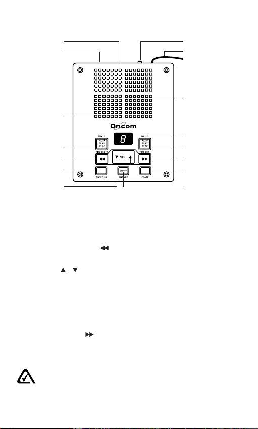
2 Location of controls
1
2
3
4
5
6
7
1. Power Jack
2. Phone Jack
3. Microphone
4. Mailbox 1 Play / Stop button with LED indicator
5. Previous Message / Time Check button
6. Greeting button
7. Volume / button
8. Ring Select Switch
9. Line cord
10. Speaker
11. LED Message Counter
12. Mailbox 2 Play / Stop button with LED indicator
13. Next Message / Time Set button
14. Erase button
15. Answer On / Off button
8
9
10
11
12
13
14
15
N13134
The A-Tick symbol indicates that this product complies with all current Australian
ACA standards.
2
Page 4

3 Installation
3.1 Check contents of pack
The following items are supplied in this pack:
• one answering system with telephone cable
• one power adaptor
• one operating Manual
• one warranty card
3.2 Install the backup battery
If AC power fails or you unplug the system, one 9 volt alkaline
battery (not supplied) is required to save recorded messages
and day/time settings.
To install battery
1. Open the battery door by pulling back the latch using a ballpoint pen.
2. Install a 9 volt alkaline battery.
3. Replace the battery door.
To replace battery
Replace the battery when ‘L’ appears on the display.
1. Unplug the telephone line from the wall jack.
2. Follow step 1 to 3 in the “To install battery” section.
3. Plug the telephone line back into the wall jack.
3.3 Connect the line cord
Plug the telephone line cable from the AM100 into the wall
socket.
Plug your phone’s line cable (not supplied) into the PHONE
JACK.
3.4 Connect the AC power
Use only the provided AM100 AC Adaptor. Plug AC adaptor into
the power jack in your unit. Plug AC adaptor into a standard 240
volt wall outlet. Do not attach (staple, etc.) the AC adaptor cord
to the building wall.
The display lights and numbers ‘0’ to ‘5’ appear sequentially on
the display. A long beep sounds and ‘0’ appears. If you did not
install a backup battery, ‘L’ and ‘0’ alternately appear.
Note: The system cannot operate without AC power.
3
Page 5

4 Preparation
4.1 Turning the System On/Off
To turn the system on, press ANSWER ON/OFF button once.
The total number of recorded messages in two mailboxes
appears on the display. The system is now set to answer calls.
To turn the system off, press ANSWER ON/OFF button once.
‘–’ appears on the display.
4.2 Adjusting the Volume
Press VOL. button to increase the volume, or VOL. button to
decrease the volume. The system beeps when you press either
volume button. When the maximum volume is reached, the
system beeps three times.
4.3 Setting the Day and Time
You must set the day and time before the system will start to
record the day/time voice stamp on each incoming message.
The day/time voice stamp automatically defaults to Monday,
12:00 AM, when you connect the system to power. The date
and time do not advance until you set the correct day and time.
1. Turn on the system.
2. Hold down / TIME SET button for about two seconds,
then release it. The system announces “Monday”.
3. Repeatedly press / TIME SET button until you hear the
correct day.
4. Press / TIME CHECK button. The system announces
“twelve”.
5. Repeatedly press / TIME SET button until you hear the
correct hour.
6. Press / TIME CHECK button. The system announces
“0”.
7. Repeatedly press / TIME SET button until you hear the
correct minute.
8. Press / TIME CHECK button. The system announces
“AM”.
9. Press / TIME SET button to select “PM”.
10. Press / TIME CHECK button to confirm the setting. The
system announces the current day of the week and the time.
11. To hear the current day and time, press / TIME CHECK
button.
4
Page 6

Notes:
• During the day/time setting, the display will turn off.
• If there is a delay of 20 seconds between any of the steps,
the system exits day/time setup mode. When you have set
the AM/PM and then wait for 20 seconds, the unit will
automatically announce the current day of the week and
the time, and exits day/time setup mode.
• If you have not set the day and time and you press /
TIME CHECK button, the system announces “Time is not
set”.
• You must reset the clock after replacing the battery.
4.4 Setting the Number of Rings
Slide the ring select switch to 2 or 6 to select the number of
rings you hear before the system answers. Slide to TS (Toll Saver)
to avoid unnecessary charges when calling long distance to
check your messages. If there are new messages, the system
answers after two rings. Otherwise, the system answers after
six rings. If you hear more than two rings, you know you can
hang up because there are no new messages.
4.5 Recording the Outgoing Message
There are approximately 40 minutes of total recording time
shared by your outgoing message and incoming messages. You
can use the system’s prerecorded outgoing message, “Hello,
please leave your message after the beep”, or record your own.
1. Hold down GREETING button until ‘0’ appears on the display
and the system beeps. Speak clearly towards the top of the
unit. The display will count from ‘0’ to ‘9’ until the recording
has stopped.
2. Release GREETING button when you are finished. The
system automatically plays back your recorded message.
During playback, “A” will appear on the display.
5
Page 7

Note:
The AM100 has two personalized mailboxes. You have an
option to have callers leave messages in either of the two
mailboxes.
If you want the caller to leave a message in a particular mailbox,
your greeting should instruct the callers to press either the “1*”
or “2*” button before their message recording. If the caller doesn’t
press a key, presses a key other than “1*” or “2*”, or waits longer
than 4 seconds before pressing a key, the caller’s message will
be automatically recorded in Mailbox 1.
Sample Message:
“Hello, this is ______________.
I can’t come to the phone right now, but please leave your name
and phone number after you hear the beep. I’ll return your call
as soon as possible. If you wish to leave a message specifically
for Bob, press “1*”, for Joan, press “2*”. Thank you for calling.”
Notes:
• The maximum length for an outgoing message is
approximately 1 minute and the minimum is about 2 seconds.
When the maximum outgoing message length is reached,
the system sounds three short tones and plays back the
message. Repeat these steps to record a new outgoing
message. At the last 10 seconds, the counting numbers will
flash.
• If you record your own message and later decide to use the
prerecorded message, hold down GREETING button until
a beep sounds. Release GREETING button, and the system
plays the prerecorded outgoing message. If you want to use
a personal greeting, you must record it again.
4.6 To Check the Greeting
1. To check the greeting, press and release GREETING button
quickly.
2. Your outgoing greeting will be played back to you, and then
your system will reset to answer incoming calls.
Note: You can stop greeting playback by pressing GREETING
button once again.
6
Page 8

5 Answering System Operation
5.1 Setting the System to Answer Calls
1. Press ANSWER ON/OFF button once to turn on the system.
2. When the system answers a call, it plays the outgoing
message then beeps.
3. The caller can leave a message up to one minute in length.
After the caller hangs up, is silent for more than seven
seconds, or the maximum message length is reached, the
system hangs up and resets to answer the next call. The
number flashes on the display to indicate an incoming
message has been recorded.
4. When the system answers a call or records a message, if
any phone on the same line is picked up or the system
detects a Calling Party Control (CPC) signal, it stops playing
the outgoing message or recording, and resets to answer
another call.
5. When the system is off ( “–” appears on the display) and
there is an incoming call, it will answer the call after 10 rings
and sound a long beep, then waits seven seconds for the
remote code.
Notes:
• When there are messages from 0-9, the display shows ‘0’
to ‘9’ respectively. If there are more than 9 messages, the
display will be flashing.
• When the memory is full, ‘F’ appears on the display. If you
try to change to OGM while the default OGM is on, the unit
will emit three beep tones and the OGM will not change. If
you already have a personal OGM, you can still change
your OGM when the memory is full.
• Many local phone companies use Calling Party Control
(CPC) to signal that a caller has hung up. Your system can
recognize a CPC signal and release the line.
• If memory reaches maximum capacity, while a caller is
leaving a message, it stops recording and hangs up
automatically.
7
Page 9

5.2 Screening Calls
To screen your calls, let the system answer. Listen to the caller’s
message through the system’s speaker. If you decide to answer
the call, pick up any phone connected to the same phone line
as the system. The system stops recording and resets to answer
the next call. In the event that the system continues recording,
press the hook switch on the telephone momentarily.
Notes:
• When the lowest volume is set, the caller’s message cannot
be heard. The standard voice prompts, beep tone, and
recorded message should not be audible at minimum volume
when any of the buttons are pressed, either.
• If you pick up the phone just as the system answers, the
system might not stop playing the message. If this happens,
press PLAY/STOP button to stop playing the message.
5.3 Recording Message into the Mailbox
You can record a message, for another member of your
household, in either of the two mailboxes (Mailbox 1 or Mailbox
2). It will be played back, along with other messages, in the
corresponding mailbox.
To Record Message:
1. Press and hold the MAIL 1 PLAY/STOP button or MAIL 2
PLAY/STOP button. A beep will sound.
2. Record your message through the microphone in the
speaker holes.
3. When your message is completed, release the button.
5.4 Playing Messages
• The Message Counter will display the total number of
messages in two Mailboxes. The number of messages flash
rapidly after the system records new messages.
• The LED of Mail 1 or Mail 2 will flash to indicate new
messages received in the corresponding mailbox.
8
Page 10

1. To listen to Mailbox 1 messages, press MAIL 1 PLAY/STOP
button. To listen to Mailbox 2 messages, press MAIL 2 PLAY/
STOP button, the Message Counter will display the message
number being played.
Note: If there are no messages, the display shows “0” and
you will only hear either “mailbox 1” or “mailbox 2” when you
press the corresponding mailbox PLAY/STOP button.
2. The system plays each new message in sequence and
announces the day and time it was recorded.
3. During message playback:
• Press / TIME CHECK button to repeat the current
message.
• Hold down / TIME CHECK button for about two
seconds to repeat the previous message.
• Press / TIME SET button to skip forward to the next
message.
To stop message playback at any time, press PLAY/STOP
button.
4. After playing all messages, the system beeps and saves
the messages. The total number of messages in two
Mailboxes appears on the display.
5. To replay all messages, press the corresponding mailbox
PLAY/STOP button.
5.5 Deleting Messages
You can delete messages individually during playback, or all at
once after playback.
To delete an incoming message (after listening to it), press
ERASE button once during playback, “E” appears on the display.
To delete all messages in the corresponding mailbox after
playback, hold down ERASE button for about two seconds. “E”
is flashing rapidly on the display, press the corresponding mailbox
button. The system beeps and all messages in the corresponding
mailbox are deleted.
Note: If you hold down ERASE button before playing back all
messages, the system beeps. You cannot delete the new
messages until you play them all back.
9
Page 11

5.6 To Reset
If an AC power failure occurs, or the AC power adaptor comes
out of the wall, your unit will shut down until the power is restored.
If your unit is not operating properly when the power is restored,
proceed with a unit reset.
1. Unplug the AC adaptor from the power outlet and telephone
line from the wall jack.
2. Replace the 9 volt alkaline battery with a fresh one.
3. Plug the AC adaptor back into the power outlet.
4. Plug the telephone line back into the wall jack.
5. Record a new outgoing announcement or you can use the
pre-recorded announcement.
6. Set the date and time.
6 Remote Operation
While you are away from your home or office, you can access
your system by remote operation. Use a touch-tone phone to
enter your remote operation security code.
6.1 Operating the System from a Remote Location
To use your system from a remote telephone, you must enter a
3-digit remote operation security code. The security code label
is located on the bottom of the unit.
1. Dial your phone number.
2. After the system answers, wait for the outgoing message
and the beep tone. Enter your remote operation security
code. The unit will emit two beeps to indicate the code was
entered correctly.
3. Enter a remote command. See “Remote Commands”.
Notes:
• If the memory is full, the system will answer calls after 10
rings, then announce “memory is full” and emit three short
beeps. You can then enter the 3-digit remote code to control
the unit.
• If you do not have CPC service and you hang up while the
system is playing back messages, the system might not
recognize that you hung up.
• If someone calls while the system is playing the messages
(in remote operation), the caller hears a busy signal.
10
Page 12

6.2 Turning Your System On
If you forget to turn your system on, you can phone in from a
remote location and turn it on automatically.
1. Call your telephone number.
2. The system answers after 10 rings. After the beep, enter
your 3-digit security code.
3. After the second beep, press 9# then hang up. Subsequent
messages will be recorded.
6.3 Remote Commands
If the correct code was accessed, you hear two beeps.
Option Press
Play messages in mailbox 1 1 #
Play messages in mailbox 2 2 #
Delete all old messages 3 #
(all messages must be played back)
Record new outgoing message 7 #
(Press 7# again to stop recording outgoing message)
Turn system off/on 9 #
Monitor the room 0 #
When you press 1# to play messages in mailbox 1, or 2# to play
messages in mailbox 2 (during playback), you can then press
the following keys to get these remote functions.
Option Press
Erase current message 3 #
Repeat previous message 6 #
Skip to next message 7 #
Repeat current message 8 #
Stop message playback # #
After all your messages have been played, you hear two short
beeps. You have 20 seconds to access the menu again,
otherwise, the unit disconnects automatically.
Note: When you are in remote playback, if there are new
messages in mailbox 1 or mailbox 2, enter the instruction “1#”
or “2#”, only new messages will be played back to you; if there
are no new messages in mailbox 1 or mailbox 2, enter the
instruction “1#” or “2#”, all messages will be played back to you.
11
Page 13

7 Important information
Temperature and ambient conditions
The telephone answering system is designed for indoor use
(temperature range of -10 °C to 50 °C). Do not install the system
in areas where there is the risk of an explosion, excessive
exposure to smoke, dust, vibrations, chemicals, moisture, and
heat. The unit must not be installed in damp locations such as a
bathroom or laundry, do not expose the unit to direct sunlight.
Cleaning and care
The surface of the case can be cleaned with a dry, soft, lint-free
cloth. Never use cleaning agents, particularly aggressive
solvents. Apar t from occasional cleaning of the case, no other
care is necessary. The rubber feet of the base station are not
resistant to all cleaning agents. The telephone feet do not
normally leave any marks on the surface. However, on account
of the multitude of varnishes and surface finishes used, surface
marks caused by the feet of the unit cannot be ruled out.
Troubleshooting
If you feel this product is not working correctly please consult
the user guide and ensure that you are using the product in
accordance with the instructions.
Remove all extra telephone equipment and connect only this
telephone directly to the telephone socket.
If the fault is still present, connect another telephone (if available)
to the telephone socket. The results will show you whether the
fault lies with this product or with the telephone line. If this
product is working correctly the fault is on the telephone line.
Please contact your network operator for assistance
In the case of technical problems with this product please consult
our website for further information or send us an email for a
prompt response to your enquiry.
12
Page 14

Warranty Information
This product is covered by a 12 month warranty against defective
workmanship or parts, effective from the date of purchase.
The warranty does not extend to damage caused by misuse,
negligence, excessive voltage, faults on the telephone line or
lightning. This warranty in no way affects your statutory rights.
Full details of the warranty are contained in the enclosed warranty
card.
Technical support
In the unlikely event of a fault during this period, please consult
our website for assistance or send us an email for a prompt
response to your enquiry. If the product is then found to be faulty
you will be asked to return it directly to us with a copy of the
purchase receipt.
For further information about the Oricom range of products
please visit our website.
Australia
Oricom International Pty Ltd
ABN 46 086 116 369
PO Box 5681
South Windsor, NSW 2756
Customer support
Email:
support@oricom.com.au
Web: www.oricom.com.au
Fax: (02) 4572 0939
Ph: 1300 889 785
New Zealand
Atlas Gentech (NZ) Ltd,
Private Bag 14927,
Panmure,
Auckland
Customer Support
Email:
support@atlasgentec.co.nz
Fax (09) 5742722
Ph: 0900 50025 (Toll Call)
13
LIBA68YY
 Loading...