


DTX4200
Keep this user guide for future reference. Always retain your proof of purchase in case of
Warranty service and register your product on line at:
AUSTRALIA: www.oricom.com.au NEW ZEALAND: www.oricom.co.nz
Operating Instructions
DTX4200 80 Channel UHF Citizen Band Radio

This unit complies with all relevant Australian
and New Zealand approval requirements
AS/NZS 4365:2011
The ACMA increased the number of available UHF CB channels.
To provide additional channel capacity within the UHF CB Band, the ACMA has increased the number of available
channels by changing from wideband to narrowband channels and adding the additional channels to the existing
40 channels. Some of the new channels are locked and cannot be used, see channel chart later in this user guide
for more information.
When did this take place?
Early in 2011, new AS/NZS Standards came into effect allowing operators to use additional narrowband channels and
also use narrowband transmissions on some current wideband channels. This increased the number of channels up
to 80, 75 of which are useable voice channels.
What issues may users experience during the transition phase?
When a new narrowband radio receives a transmission from an older wideband radio, the speech may sound loud
and distorted – simply adjust your radio volume for the best listening performance. When an older wideband radio
receives a signal from a new narrowband radio, the speech may sound quieter – simply adjust your radio volume
for best listening performance. When operating a narrowband radio or Channel 41 - 80 interference is possible from
wideband radios transmitting on high power or on adjacent frequency.
The issues described above are not a fault of the radio but a consequence of mixed use of wideband and narrowband
radios.
It is expected that as older wideband radios are removed from service that this issue will be resolved. Most radios in
use will be narrowband eliminating this issue.
This information is current at time of printing. For further up to date information please visit
www.acma.gov.au

3
Table of contents
Introduction ..................................................................................4
Important information ...................................................................5
Installation of your Oricom Radio...................................................6
Controls and Indicators ................................................................. 8
Operations .................................................................................. 12
UHF CB channels and frequencies ..............................................27
Express Warranty (Australia) .......................................................31
Need Help?
If you need assistance setting up or using your Oricom product now or in
the future, call Oricom Support.
Australia 1300 889 785 or (02) 4574 8888
www.oricom.com.au
Mon-Fri 8am – 6pm AEST
New Zealand 0800 67 42 66
www.oricom.co.nz
Mon-Fri 10am – 8pm NZST

4
Introduction
Introduction
Thank you for choosing the Oricom DTX4200 5 watt UHF CB Radio.
Key Features
Dual receive
IP54 dust and splash resistant
12/24 volt operation
3 memory groups of 16 channels per group
96 Multi-colour backlit display
Backlight brightness (5 pre-set levels plus auto)
Fast scanning 80 channels within 3 seconds
Rotary volume/channel and squelch control
Duplex
38 CTCSS & 104 DCS codes
Heavy duty diecast metal chassis
Slide-in mounting bracket
Auto power off (off/1h/2h/4h)
3.5mm external jack (for optional external speaker or PA adaptor)
Optional Accessories
External speaker
PA adaptor jack
PC programming cable and software to allow programming of memory
location

5
Important information
Please read before installing or operating your
Oricom Radio
The operation of your UHF radio in Australia and New Zealand is subject
to conditions in the following licenses:
In Australia the ACMA Radio communications (Citizen Band Radio
Stations) and in New Zealand by MED the General User Radio License
for Citizen Band Radio.
Safety Information and Warnings
WARNING
Potentially Explosive Atmospheres
Turn your radio OFF when in any area with a potentially
explosive atmosphere. Sparks in such areas could cause an
explosion or re resulting in injury or even death.
NOTE: Areas with potentially explosive atmospheres are often,
but not always clearly marked. They include fuelling areas such
as below deck on boats; fuel or chemical transfer or storage
facilities; areas where the air contains chemicals or particles,
such as grain, dust, or metal powders; and any other area where
you would normally be advised to turn off your vehicle engine.
Blasting Caps and Areas
To avoid possible interference with blasting operations, turn
your radio OFF near electrical blasting caps or in a “blasting
area” or in areas posted: “Turn off two way radios.” Obey all
signs and instructions.
Electromagnetic Interference/Compatibility
Nearly every electronic device is susceptible to electromagnetic
interference (EMI). To avoid the possibility of electromagnetic
interference and/or compatibility conicts, turn off your radio
in any location where posted notices instruct you to do so such
as health care facilities.

6
Installation of your Oricom Radio
CAUTION
When installing your radio in your vehicle, check that during
installation you do not damage any wiring or vehicle components
that may be hidden around the mounting position. Ensure
the installation does not interfere with the operation of the
vehicle and meets all regulatory and safety requirements for
accessories tted to your vehicle.
For optimum performance your radio needs to be installed
correctly. If you are unsure about how to install your radio, we
suggest you have your radio professionally installed by a UHF
specialist or Auto electrician. When installing the radio, avoid
mounting it close to heaters or air conditioners. Never press
the PTT or CALL button before connecting the antenna to the
radio.
Wiring Methods
There are two possible wiring congurations for connecting to the
vehicles power supply.
A. Radio stays ON when the ignition is switched OFF
Connect the radio’s negative (black) lead to the vehicle chassis, or
directly to the battery’s negative terminal.
Connect the radio’s positive (red) lead via the 2 Amp fuse to the
battery’s positive terminal. Alternatively, the positive lead could be
connected at the fuse box at a point that has DC Power continuously
available (preferably the battery side of the ignition switch) via the 2
Amp fuse.
B. Radio turns OFF with the ignition switch
Connect the radio’s negative (black) lead to the vehicle’s chassis, or
directly to the battery’s negative terminal.
The radio’s positive (red) lead should connect to an accessory point in
the vehicle’s fuse box via the 2 Amp fuse.

7
Installation of your Oricom Radio
Antenna information
The antenna (not supplied) is of critical importance, to maximize your
output power and receiver sensitivity.
A poorly installed, inferior quality antenna or one not designed for the
correct frequency band will give poor performance. You should only
purchase an antenna designed for the 477MHz frequency band.
Antenna installation
1. Connect the antenna to the rear antenna socket using a PL259 coaxial
connector (not supplied).
2. To obtain maximum performance from the radio, select a high quality
antenna and mount it in a good location. Never press the PTT or
CALL button before connecting the antenna to the radio.
3. For best performance always mount your antenna as high as possible
and away from all other antennas or poles.
Optional External Speaker
Depending on the installation it may be necessary to use an external
speaker (not supplied) to give improved volume and clarity. This can be
plugged into the EXT –SPK socket on the rear of the unit.
8
Controls and Indicators
Controls and Indicators
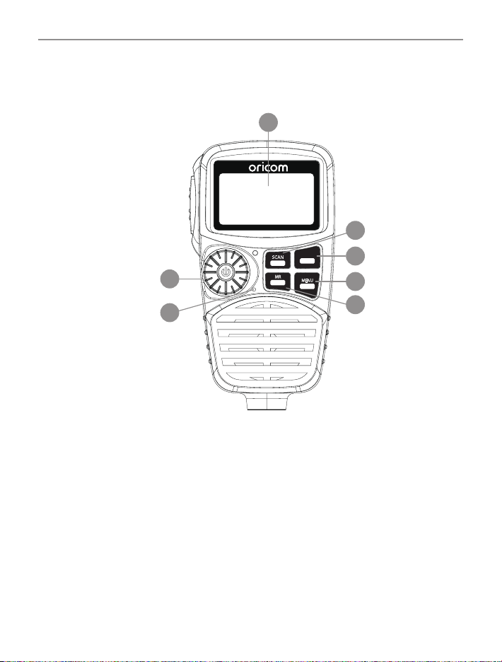
Front View
SCAN
RM
MR
MW
SWP
SRX
MENU
GTS
6
1
2
4
5
3
7
1. Power on/off and Volume/channel/squelch selector and SVL
(sub receiver volume)
2. Scan (open scan/memory group scan)/remove memory
3. Memory recall/memory write
4. Main & Sub channel swapping/SRX on/off
5. Menu/Group tone scan
6. Microphone
7. LCD display
9
Controls and Indicators
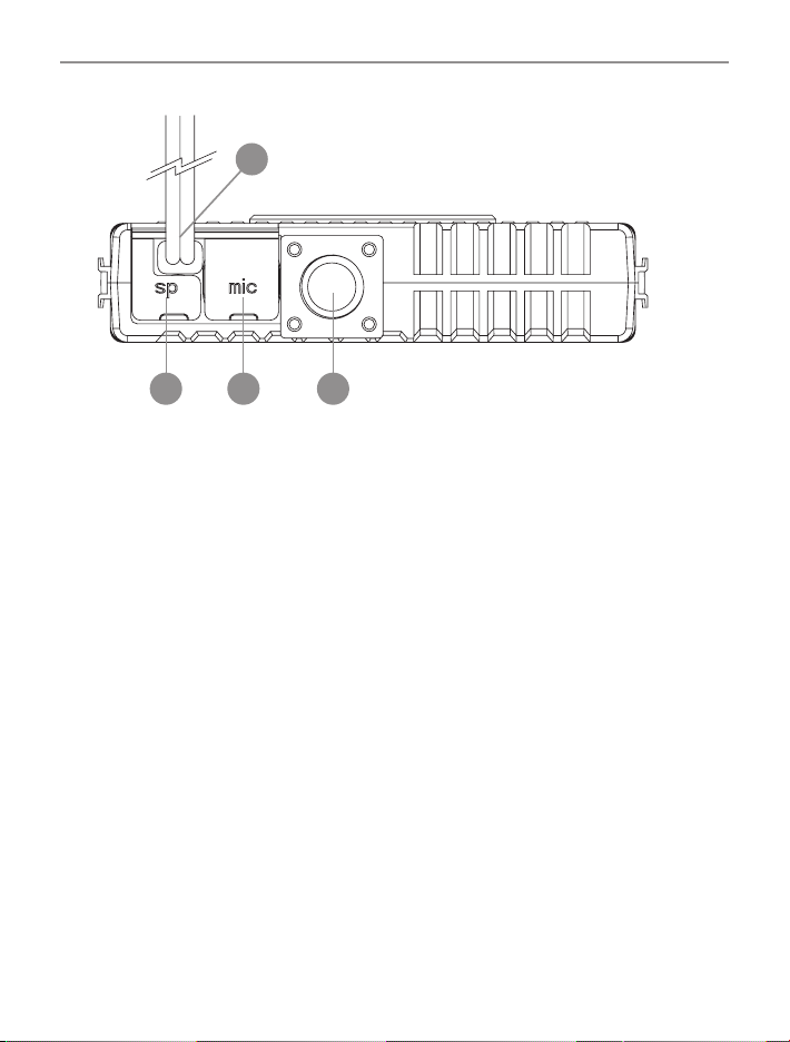
Rear View
1
2
3 4
1. 3.5mm external jack for optional 8 ohm speaker and PA speaker
2. Power supply connection
3. Computer programming connector
4. Antenna Connection
10
Controls and Indicators
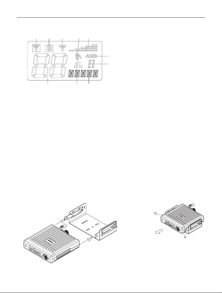
LCD Icons & Indicators
245
6
7
8
3
1
10
9
1. Sub receiver busy 6. Group display (A, B, C groups)
2. Sub receiver on 7. Group address channel
3. Main receiver busy 8. Status display
4. Duplex on 9. CTCSS or DCS on
5. Signal strength & TX power 10. Channel display
TO MOUNT: SLIDE
INTO UNIVERSAL
MOUNTING BRACKET
TO REMOVE:
SLIDE OUT HOLDING
BRACKETS AWAY FROM
UHF RADIO
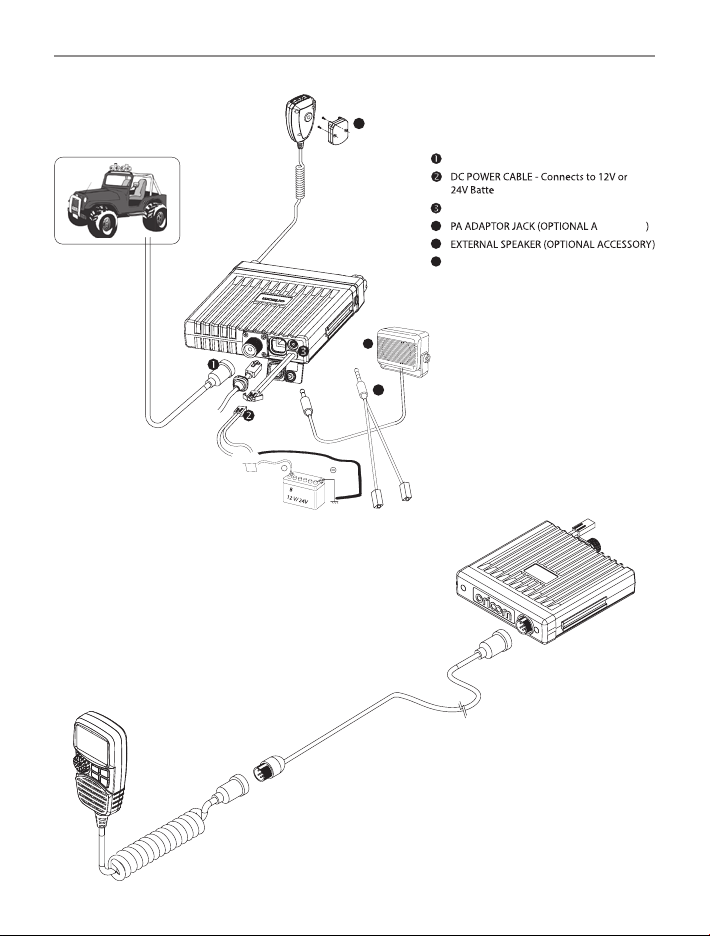
Installation of the DTX4200 and tting optional accessories
Mounting the UHF radio
The universal mounting bracket supplied with your UHF radio allows
overhead/dash mounting.
Mount the UHF radio via the bracket, securely with the supplied screws in
the desired location, ensuring the surface is sturdy and can support the
weight of the radio.
11
Controls and Indicators
ANTENNA CONNECTOR
4
5
MICROPHONE HANGER - Fit the supplied
micrphone hanger in the desired location.
6
ry. Pay attention to polarities.
EXTERNAL SPEAKER JACK
CCESSORY
red:
+
black:
attery
TO CHASSIS
FUSE
(OPTIONALACCESSORY)
EXTRA MIC LEAD
(OPTIONALACCESSORY)
EXTERNAL SPEAKER
(OPTIONAL ACCESSORY)
- - - - - - - - - - - - - - - - - - - - - - --
- - - - - - - - - - - - - - - -
_________or ________
O
6
4
RED for extension
speaker
Yellow for PA
speaker
5
Installation Diagram
 Loading...