

Page 1
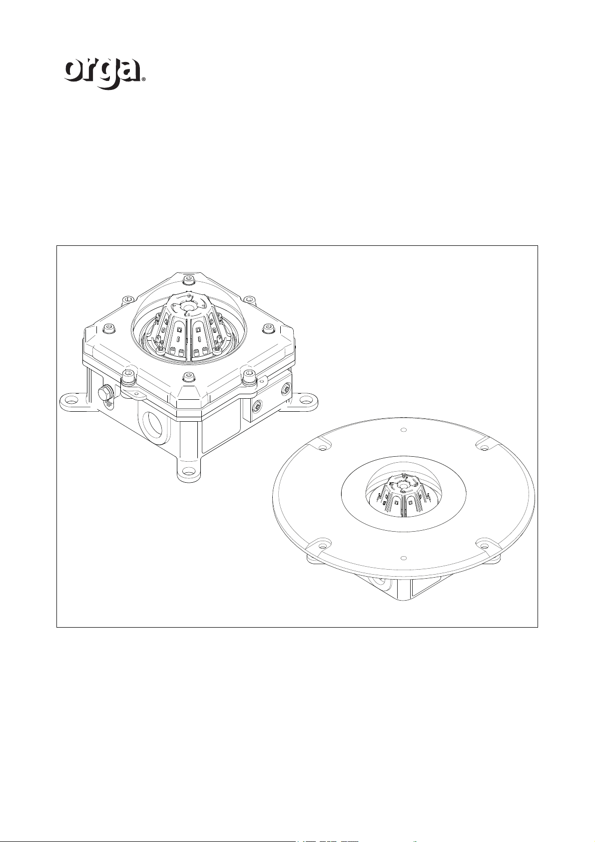
L85EX Lighting fixture
Installation and maintenance manual
Perimeter light
Aeronautical Obstruction light
/i
ORGA BV
Strickledeweg 13
3125 AT SCHIEDAM
The Netherlands
T +31 (0) 10 208 5555
I www.orga.nl
Page 2

Copyright
2016 Orga. All rights reserved.
Disclaimer
While every effort has been made to provide a complete, up-to-date, accurate manual, Orga will accept no
liability claims for damages resulting from any errors or omissions in this manual.
Page 3

Table of contents
1 INTRODUCTION
1.1 Before you begin .................................................................................................................... 5
1.2 Abbreviations and terminology ...............................................................................................5
1.3 Icons used in this document................................................................................................... 6
2SAFETY
2.1 Intended use........................................................................................................................... 7
2.2 Label....................................................................................................................................... 7
2.3 Installation .............................................................................................................................. 8
2.4 Operation................................................................................................................................ 8
2.5 Maintenance and repair.......................................................................................................... 8
2.6 Ex certificates ......................................................................................................................... 8
2.6.1 ATEX certification.......................................................................................................8
2.6.2 IECEx certification ......................................................................................................8
2.6.3 EC - Declaration of Conformity .................................................................................. 8
2.7 Warranty policy....................................................................................................................... 9
1 DESCRIPTION
1.1 Overview .............................................................................................................................. 11
1.1.1 Description ............................................................................................................... 11
1.2 Overview of the recessed version ........................................................................................ 12
1.3 Product types ....................................................................................................................... 13
1 INSTALLATION
1.1 Unpack the delivery .............................................................................................................. 15
1.2 Preparation........................................................................................................................... 15
1.3 Safety during installation ...................................................................................................... 15
1.4 Installation of L85EX ............................................................................................................ 16
1.4.1 Install the light fixture ............................................................................................... 16
1.4.2 Open the cover assembly ........................................................................................ 16
1.4.3 Connect the power supply cable .............................................................................. 16
1.4.4 Connect the wiring of the lighting fixture .................................................................. 17
1.4.5 Close the cover assembly ........................................................................................ 18
1.5 Installation of L85EX Recessed ........................................................................................... 19
1.5.1 Open the cover assembly ........................................................................................ 19
1.5.2 Connect the power supply cable .............................................................................. 19
1.5.3 Connect the wiring of the lighting fixture .................................................................. 19
1.5.4 Close the cover assembly ........................................................................................ 20
1.5.5 Install the light fixture ............................................................................................... 20
2 ACCESS TO PARTS
2.1 Open the cover assembly.....................................................................................................23
2.2 Close the cover assembly ....................................................................................................23
2.3 Open the cover assembly of the recessed version............................................................... 24
2.4 Close the cover assembly of the recessed version .............................................................. 24
3 MAINTENANCE
3
Page 4

3.1 Advised maintenance schedule............................................................................................ 25
3.2 Maintenance procedures ......................................................................................................25
4 TROUBLESHOOTING
4.1 Failure of the light fixture ...................................................................................................... 27
4.2 Check the electrical connections .......................................................................................... 28
4.3 Replace the dome ................................................................................................................ 29
5 TECHNICAL DATA
5.1 Mechanical specification....................................................................................................... 31
5.1.1 Perimeter light L85EX-G-AC .................................................................................... 31
5.1.2 Perimeter light L85EX-G-AC-RE .............................................................................. 33
5.1.3 Aeronautical obstruction light L85EX-R-AC-10 ........................................................ 34
5.1.4 Aeronautical obstruction light L85EX-R-AC-32 ........................................................ 36
5.1.5 Aeronautical obstruction light L85EX-R-AC-50 ........................................................ 37
5.1.6 Aeronautical obstruction light L85EX-R-AC-200 ...................................................... 38
5.1.7 Perimeter light L85EX-B-AC..................................................................................... 39
5.1.8 Perimeter light L85EX-Y-AC..................................................................................... 40
5.1.9 Perimeter light L85EX-G-DC .................................................................................... 41
5.1.10 Perimeter light L85EX-G-DC-RE .............................................................................. 42
5.1.11 Aeronautical obstruction light L85EX-R-DC-10 ........................................................ 43
5.1.12 Aeronautical obstruction light L85EX-R-DC-32 ........................................................ 45
5.1.13 Aeronautical obstruction light L85EX-R-DC-50 ........................................................ 46
5.1.14 Aeronautical obstruction light L85EX-R-DC-200 ...................................................... 47
5.1.15 Perimeter light L85EX-B-DC .................................................................................... 48
5.1.16 Perimeter light L85EX-Y-DC .................................................................................... 49
5.2 Accessories .......................................................................................................................... 50
5.2.1 Swivel elbow adapter for cable gland (optional for recessed versions).................... 50
5.3 Site specifications................................................................................................................. 50
5.3.1 Cavity sizes for the recessed versions ..................................................................... 50
5.4 Labels ................................................................................................................................... 51
5.4.1 Labels....................................................................................................................... 51
5.4.2 Labels....................................................................................................................... 52
A DELIVERY AND SPARE PARTS ........................................................................ 53
A.1 Delivery information L85EX ................................................................................................. 53
A.2 Spare parts .......................................................................................................................... 54
B ATEX CERTIFICATE ...........................................................................................55
B.1 EC-Type Examination certificate L85EX ............................................................................. 55
C IECEx CERTIFICATE ..........................................................................................59
C.1 IECEx Certificate of Conformity L85EX ............................................................................... 59
D EC - Declaration of Conformity ......................................................................... 65
D.1 EC - Declaration of Conformity L85EX ................................................................................ 65
E Ex CERTIFICATE ................................................................................................ 67
E.1 Ex Certificate of Conformity L85EX (optional) ..................................................................... 67
4
Page 5
1 INTRODUCTION
This manual gives information about:
• Installation
• Operation
• Maintenance
• Troubleshooting
1.1 Before you begin
Before you start with the installation, operation, maintenance or troubleshooting on the
Lighting fixture L85EX:
WARNING
Do not continue before you understand the content of this manual.
1. Familiarize yourself with the content on this manual.
2. Identify all components of the system. Refer to Appendix A.
1.2 Abbreviations and terminology
/i
INTRODUCTION
Abbreviation / term Description
Cable gland (A device designed to) attach and secure the end of a cable to the
equipment.
Connection The electrical connection to connect components electrically.
Control panel Cabinet with terminals for the connection of electrical wiring and
operating elements for the system.
Cover Flat part that closes the product.
Connection box Compartment where the electrical wiring is collected and is led to
the control panel.
Dome The transparent cover that protects the lamps.
Label Sticker or type plate with information of the system.
Light fixture A light fixture with a transparent or translucent protective dome
Power supply cable Connects the connection box of the light fixture with the
control panel.
Terminal Electrical connection block, inside connection box.
Version 2.1 5
Page 6
INTRODUCTION
1.3 Icons used in this document
The icons below are used in this document to indicate danger or to give extra information.
/i
WARNING
Can cause personal injury.
WARNING
Electrical danger. Can cause personal injury.
CAUTION
Can cause damage to the equipment.
NOTE
Gives further/extra information.
6 Version 2.1
Page 7
2SAFETY
20XX
Serial No. :
12345678AAwwyyxxxx
WARNING:XXXXXXXXXXXXXXXXXXXXXXXXXXXXXXX
XXXXXXXXXXXXXXXXXXXXXXXXXXXXXXXXXXXXXXX
XXXXXXXXXXXXXXXXXXXXXXXXXXXXXXXXXXXXXXX
XXXXXXXXXXXXXXXXXXXXXXXXXXXXXXXXXXXXXXX
XX-XXVac; XX-XXHz
XX W; XVA
XXXXXXXXXXXXXXXXX
IECEx DEKxxxxxx X
-XX °C ≤ Ta ≤
+XX °C
!
0344
Strickledeweg 13
NL - 3125AT Schiedam
T +31 (0)10 208 5555
[email protected] - www.orga.nl
OCP 0034
Warning: XXXXXXXXXXXXXXXXXXXXXXXXXXXXXXXXX
XXXXXXXXXXXXXXXXXXXXXXXXXXXXXXXXXXXXXXXX
XXXXXXXXXXXXXXXXXXXXXXXXXXXXXXXXXXXXXXXX
XXXXXXXXXXXXXXXXXXXXXXXXXXXXXXXXXXXXXXXX
NCC: xx.xxxx X
Ex e mb IIC Tx Gb
-XX °C ≤ Ta ≤+XX °C /IP66
Strickledeweg 13
NL - 3125AT Schiedam
T +31 (0)10 208 5555
[email protected] - www.orga.nl
2.1 Intended use
The L85EX must only be used at offshore helicopter decks as perimeter light or as
aeronautical obstruction light. The lantern complies with the CAP437, ICAO annex 14 and
the IMO MODU Code.
The red type of lantern also complies to the CAP168 regulations and the Dutch Mining
Regulations.
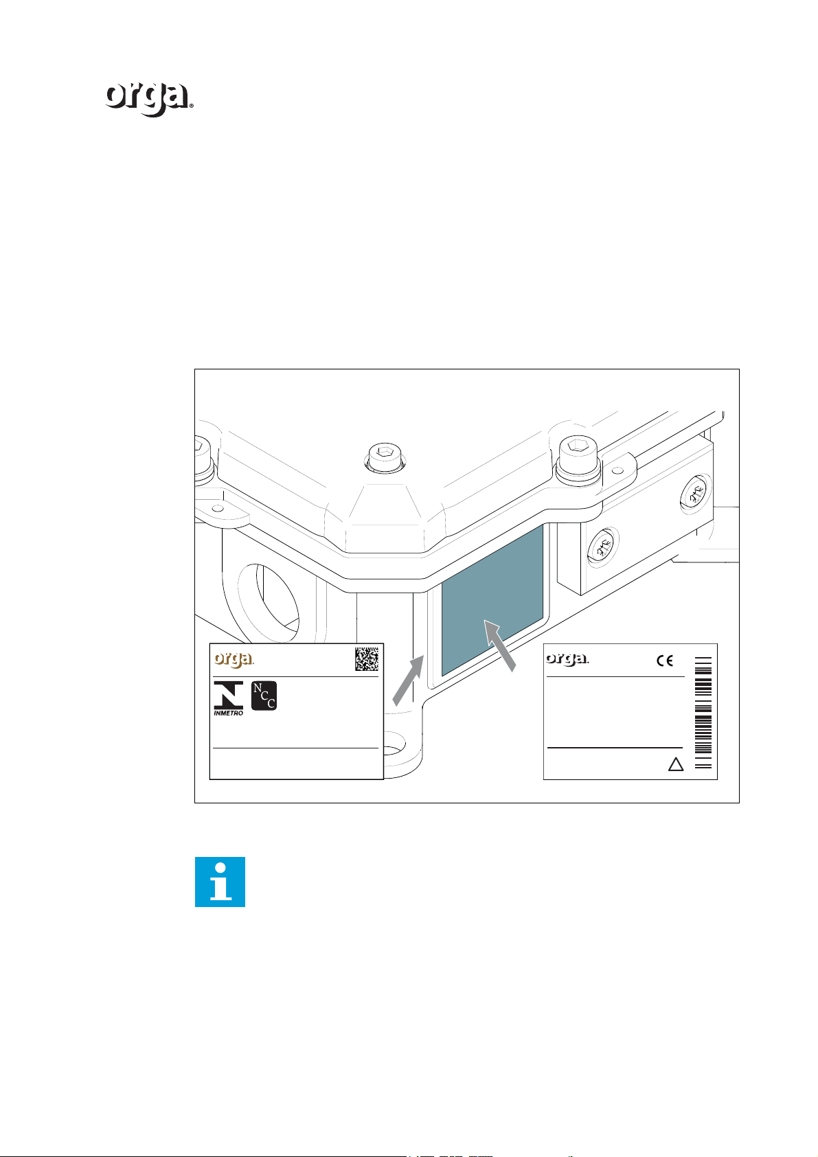
2.2 Label
SAFETY
Version 2.1 7
A ATEX and IECEx label on L85EX lighting fixture
Note
Refer to 5.4 to view the exact label.
Page 8

SAFETY
2.3 Installation
WARNING
Only an electrical engineer is allowed to do the electrical installation.
WARNING
Make sure that the mains power supply is disconnected before you start the
electrical installation.
WARNING
Make sure you comply with the (pre)conditions for electrical systems in
explosive atmospheres.
CAUTION
The L85EX is suitable for use in locations with a low risk of mechanical
danger.
2.4 Operation
There are no specific safety precautions necessary.
2.5 Maintenance and repair
WARNING
Make sure that the mains power supply is disconnected before you start the
electrical installation.
2.6 Ex certificates
This lighting fixture complies with the instructions and safety precautions in the Ex
certificates. Both certificates show the applied Safety standards.
2.6.1 ATEX certification
The lighting fixture complies with the regulations as shown in the ATEX certification and is
suitable for use in areas with an explosive atmosphere. Refer to Appendix B.
2.6.2 IECEx certification
The lighting fixture complies with the regulations as shown in the IECEx certification and is
suitable for use in areas with an explosive atmosphere. Refer to Appendix C.
2.6.3 EC - Declaration of Conformity
The lighting fixture complies with the regulations as shown in the EC - Declaration of
conformity. Refer to Appendix D.
8 Version 2.1
Page 9

2.7 Warranty policy
THE FOLLOWING IS THE STANDARD LIMITED WARRANTY FOR THE
ORGASYSTEMS AND PRODUCTS (“PRODUCTS”) SUPPLIED BY ORGA
B.V.,SCHIEDAM – THE NETHERLANDS, HEREINAFTER: “ORGA”. THIS
WARRANTYAPPLIES UNLESS A DIFFERENT WARRANTY HAS BEEN
SPECIFICALLYAGREED TO AND SIGNED BY AN ORGA AUTHORISED
REPRESENTATIVE.
LIMITED WARRANTY
(a) ORGA warrants, subject to the following limitations, that at time of delivery to Buyer, its
Products will conform to applicable ORGA drawings and Product specifications and will be
free from defects in workmanship and material. Ifapplicable, ORGA warrants that at the
time of delivery Products are compliant to applicable national and/or international rules
and regulations. However, unauthorised maintenance or repair could invalidate
compliance with such rules and regulations.
(b) The Products are not in conformity as meant under (a) in the case of a defect in
workmanship or material becoming apparent under normal authorised use consistent with
ORGA Product instructions and specifications. Normal wear and tear (includingbut not
limited to lamp failure) or problems with electrical power, relatively minor anomalies which
are customary and/or technically unavoidable, or the need forperiodic maintenance shall
not constitute non-conformity.
SAFETY
These warranties shall be available to the initial purchaser, and may be transferable to its
successors and assigns.
The duration of these warranties shall be as follows: Twelve (12) months after
commissioning, with a maximum of eighteen (18) months after shipment of the Product ex
works, Schiedam, the Netherlands
(c) All Products repaired or replaced hereunder shall be warranted only for theunexpired
portion of the original warranty period. If ORGA is of the opinion that thecomplaint about
the defect is justified, ORGA will repair or replace at its own optionany faulty Product
returned within the warranty period at its cost (including materialand labour costs,
excluding shipping costs). Repaired or replaced Products will bedelivered ex works,
Schiedam, the Netherlands1). The risk of loss or damage to allProducts in transit shall be
borne by Buyer.
(d) The integrity and reliability of ORGA systems and Products are dependent on theuse of
ORGA parts and components. To ensure the optimum performance andreliability of your
ORGA system, it is strongly advised that only components andmodules manufactured by
ORGA be used. No other parts can be used without priorwritten permission from ORGA.
Any right under this warranty shall lapse if the Product has been exposed or subjected to
1 Any maintenance or lack of maintenance, repair, installation, handling, transportation,
storage, operation, treatment, failure to observe the instructionsfor use or use which is
improper, excessive or otherwise is not in compliance withORGA’s instructions; or
2 Any direct intervention, alteration, modification, transformation or repair byanyone
other than ORGA or those specifically authorised in writing by ORGA,without prior
written permission from ORGA; or
3 Any accident, contamination, foreign object damage, abuse, misuse, neglect,
negligence or any other circumstances after delivery to Buyer; or
1)
.
1) EXW, Incoterms
Version 2.1 9
Page 10

SAFETY
4 Any damage induced by failure of an Orga supplied Product not under warranty or by
any Product not supplied by Orga.
Orga shall not be responsible for Buyer's or any third party's Product, Product information,
or memory data contained in, sorted on, or integrated with any Product returned to Orga,
whether under warranty or not. Buyer is responsible for backing up its programs and data
to protect against loss or corruption.
(e) Repair or redelivery as meant in the previous paragraphs shall in principle be effected
only within the Netherlands. Repair and or redelivery outside the Netherlands shall only be
effected if this can reasonably be requested of Orga, such to be judged exclusively by
Orga.
With respect to noticeable defects, the Buyer must submit a claim in writing within three (3)
working days after delivery, failing which any claim on Orga will lapse.
Claims with respect to other defects must be made in writing within ten (10) working days
after their appearance, failing which any claim on Orga will lapse.
In respect of Products or parts of Products which Orga received from third parties, the
warranty obligations granted by Orga to the Buyer shall never exceed in nature nor in
duration the warranty obligations granted by those third parties to Orga.
(f) This warranty is exclusive and in lieu of all other warranties, whether written or oral,
express, implied or statutory, including, without limitation, any implied warranties of
merchantability, fitness for particular purpose, or non-infringement, all of which are hereby
expressly disclaimed. No extension or expansion of this warranty shall be binding upon
Orga unless set forth in writing and signed by Orga's authorised representative.
(g) All disputes existing between parties shall be heard exclusively by the Rotterdam
District Court, unless Orga prefers another competent forum. This warranty notice is
subject to Dutch law. The stipulations specified in the Convention of International Sale of
Goods of 11 April 1980 (Weens Koopverdrag) do not apply, nor does any future
international regulation concerning the purchase of moveable property of which parties
can make use.
(h) Orga reserves the right to modify its warranty at any time, at its sole discretion.
10 Version 2.1
Page 11
1 DESCRIPTION
A
B
C
D
E
F
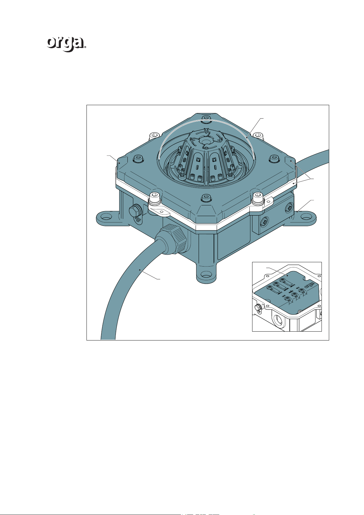
1.1 Overview
DESCRIPTION
ADome
B Cover assembly
CHousing
D Control unit
E Power supply cable to control panel
F Clamping ring
1.1.1 Description
The lighting fixture or aeronautical obstruction light, L85EX marks the offshore helicopter
deck and obstructions for aviation traffic.The perimeter light is steady burning. The lighting
fixture is explosion proof.
Version 2.1 11
Page 12
DESCRIPTION
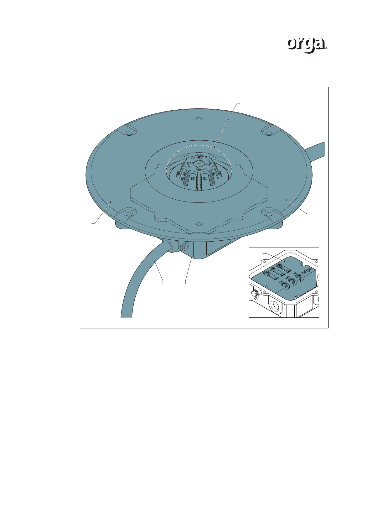
1.2 Overview of the recessed version
F
A
B
E C
ADome
B Cover assembly
CHousing
D Control unit
E Power supply cable to control panel (not supply of scope)
F Clamping ring
D
12 Version 2.1
Page 13
1.3 Product types
/i
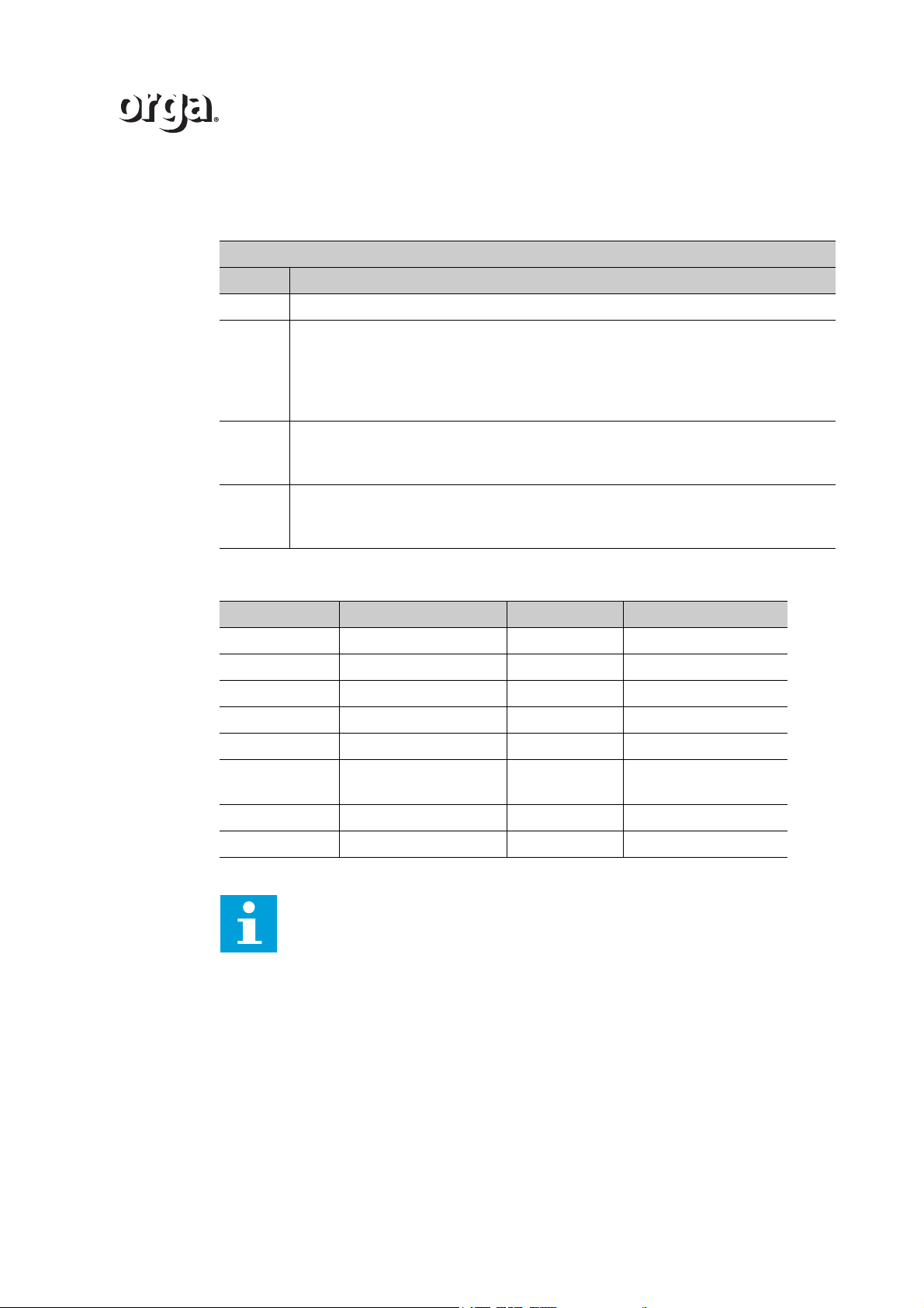
Table 1 Type identification
L85EX - x - yy - zz
Code Description
L85EX Product type
x Colour:
• G = green
• R = red
• B = blue
• Y = yellow
yy Power supply reference:
• AC
• DC
zz Additional references:
• [no.] = light intensity
• RE = Recessed
DESCRIPTION
/i
Table 2 Product types
Type number Description Type number Description
L85EX-G-AC Green, 30cd (60cd max.) L85EX-G-DC Green, 30cd (60cd max.)
L85EX-G-AC-RE Green, 30cd (60cd max.) L85EX-G-DC-RE Green, 30cd (60cd max.)
L85EX-R-AC-10 Red, 10cd minimum L85EX-R-DC-10 Red, 10cd
L85EX-R-AC-32 Red, 32 cd minimum L85EX-R-DC-32 Red, 32cd
L85EX-R-AC-50 Red, 50cd L85EX-R-DC-50 Red, 50cd
L85EX-R-AC-200 Red, 200cd L85EX-R-DC-
200
L85EX-B-AC Blue, 10 cd c L85EX-B-DC Blue, 10cd
L85EX-Y-AC Yellow, 10 cd L85EX-Y-DC Yellow, 10cd
Red, 200cd
Tip
refer to chapter 5 for more product information
Version 2.1 13
Page 14

DESCRIPTION
14 Version 2.1
Page 15
1INSTALLATION
1.1 Unpack the delivery
1. Check if the delivery is complete. Refer to the Appendix.
2. Check your delivery on damage.
3. Report damages or missing parts immediately to Orga. Refer to the contact
information on the last page.
1.2 Preparation
1. Collect the correct installation materials. These are not included in the delivery:
• IECEx or ATEX certified cable glands. The cable gland must meet the
specifications:
- suitable for the supplied power supply cable (min. three cores for L, N and
PE) and suitable for a M25x1.5 cable entry;
- suitable for ambient temperatures as specified in chapter 5;
- with ingress protection of at least IP66;
- certified to EN60079-0:2009, EN60079-7:2007 and EN60079-18:2009
(ATEX) or IEC60079-0: 2007-10, IEC60079-7: 2009 and IEC60079-18:
2006-07 (IECEx);
• 4 max.M10 (fixing) bolts;
• PE wire, cross-sectional area min. 4 mm
INSTALLATION
2
.
1.3 Safety during installation
WARNING
The permitted short circuit current is maximum 35 A.
WARNING
Before you start the electrical installation, make sure that:
- the mains power supply is disconnected, and
- the 24 Vdc is separated from the electrical system.
WARNING
Make sure that the external earth connection on the platform is located within
30 centimetres of the lantern.
Version 2.1 15
Page 16
INSTALLATION
A
B
C
A
B
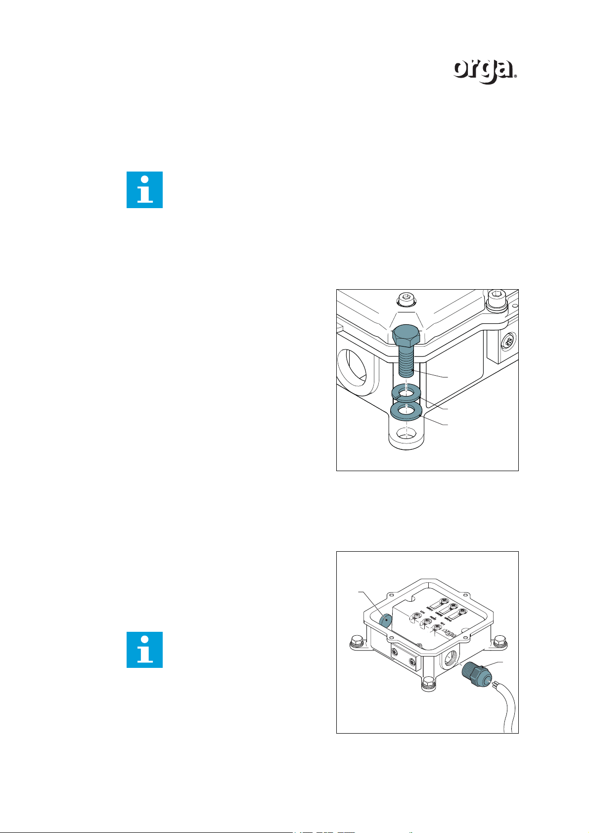
1.4 Installation of L85EX
1.4.1 Install the light fixture
Note
• The light fixture must be installed on a rigid, horizontal surface, in a posi-
tion that meets the specific visibility requirements.
• Always use fixing bolts, nuts and locknuts to horizontally level the lighting
fixture.
• Keep an open space of 1 m around the light fixture for maintenance pur-
poses.
Orga advises to install the light fixture according to the procedure below:
1. Install the light fixture with the cables
sideways (because of the looping).
2. Fasten the light fixture to the surface.
• Fasten the foot of the base with a bolt
(A), a suitable spring lock washer (B)
and washer (C).
• Fasten each foot of the base.
3. Make sure that the light fixture is
horizontally levelled. Use a spirit level
device.
4. Install the light fixture electrically.
1.4.2 Open the cover assembly
1. Open the cover assembly. Refer to section 2.1.
1.4.3 Connect the power supply cable
1. Fasten the power supply cable with the
cable gland (A)
2. Close the second cable entry with a blind
plug (B).
3. Connect the cable to the control panel (not
included).
Note
For looping (daisy chaining), use
two power supply cables and two
cable glands.
16 Version 2.1
Page 17
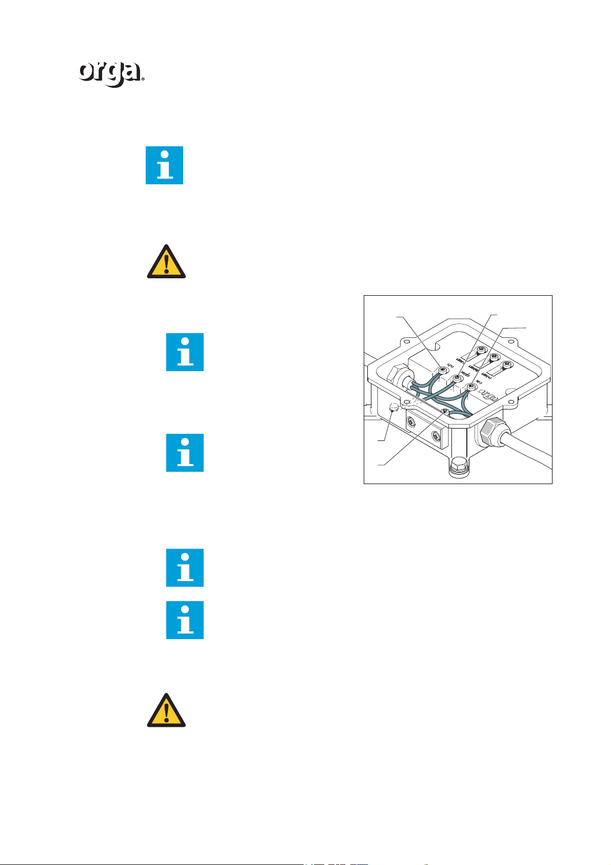
1.4.4 Connect the wiring of the lighting fixture
N(-)
PE
L(+)
A
B
Note
The procedure below applies to each lighting fixture on the platform.
Looping of the lighting fixture
WARNING
Only use cable lugs of the eyelet type.
1. Connect the live wire of the cables with
terminal L. Apply a torque of minimum
0.75 and maximum 1.25 Nm.
Note
In case of a DC execution, connect the (+) wire to the (+) terminal.
INSTALLATION
2. Connect the neutral wire of the cables with
terminal N. Apply a torque of minimum
0.75 and maximum 1.25 Nm.
Note
In case of a DC execution, connect the (-) wire to the (-) terminal.
3. Connect the earth wire of the cables to the earth connection (A) in the housing. Apply
a torque of minimum 0.75 and maximum 1.25 Nm.
4. When looping the lighting fixture, connect terminal (PE) to the earth connection (B) in
the housing. Apply a torque of minimum 0.75 and maximum 1.25 Nm.
Note
The internal earth wire is already connected.
Note
Connect the looping cable with cable lugs of the eyelet type. Use one eyelet cable lug for each earth connection.
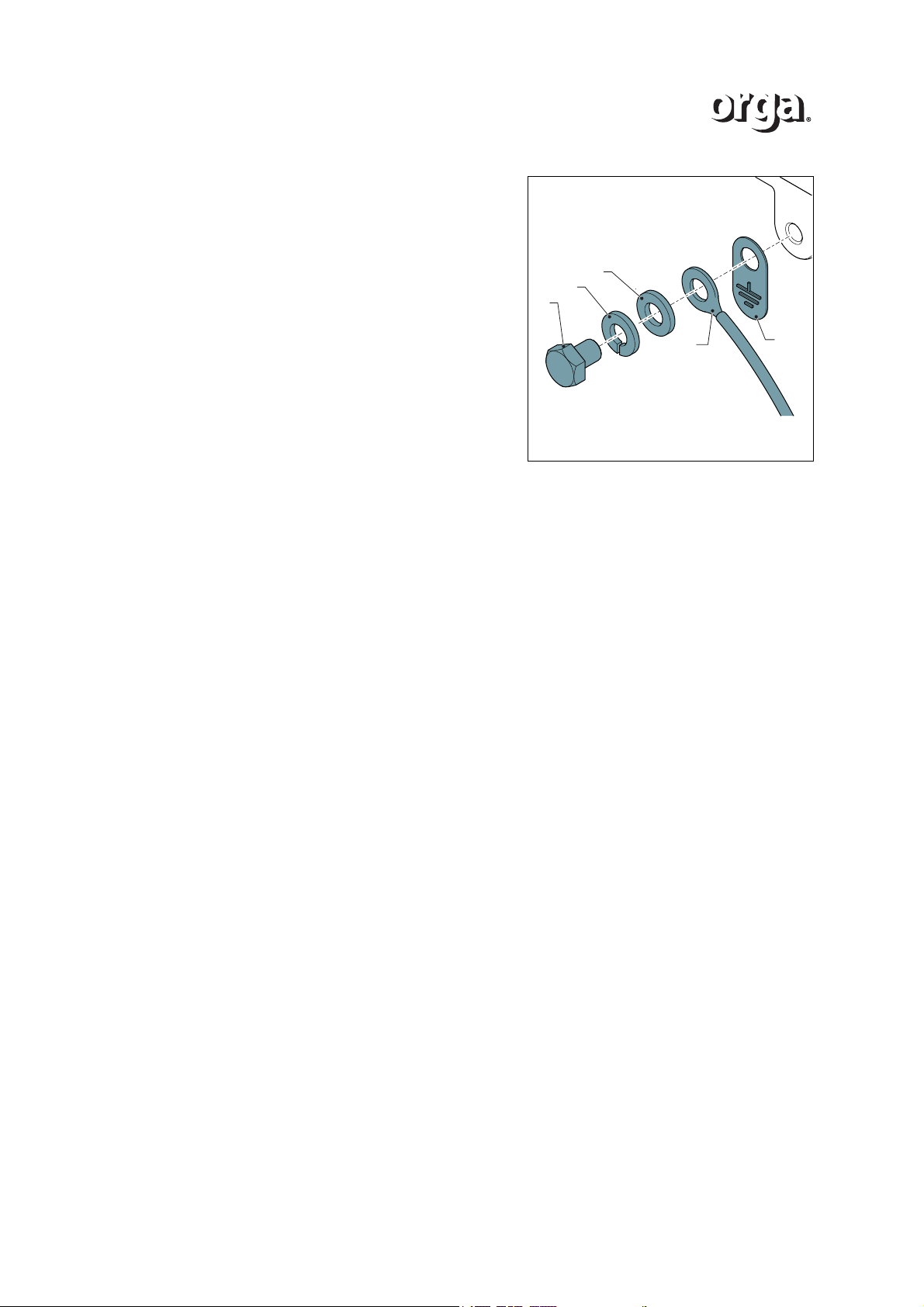
External earth connection
WARNING
Make sure that the external earth connection on the platform is located within
30 centimetres of the light fixture:
- to prevent loosening;
- to prevent twists.
Version 2.1 17
Page 18
INSTALLATION
D
A
B
C
E
1. Connect the metric M6 connection on the
foot of the base with an earth cable
mounting bolt (A) to a grounded structure
on the platform.
- Place the earthing tag (E) on the
base.
- Use a PE wire with a cross-sectional
area of at least 4 mm
cable lug (D).
- Use a M6 earth cable mounting bolt
(A) in combination with the provided
spring lock washer (B) and washer
(C).
1.4.5 Close the cover assembly
1. Close the cover assembly. Refer to section 2.2.
2
with a supplied
18 Version 2.1
Page 19
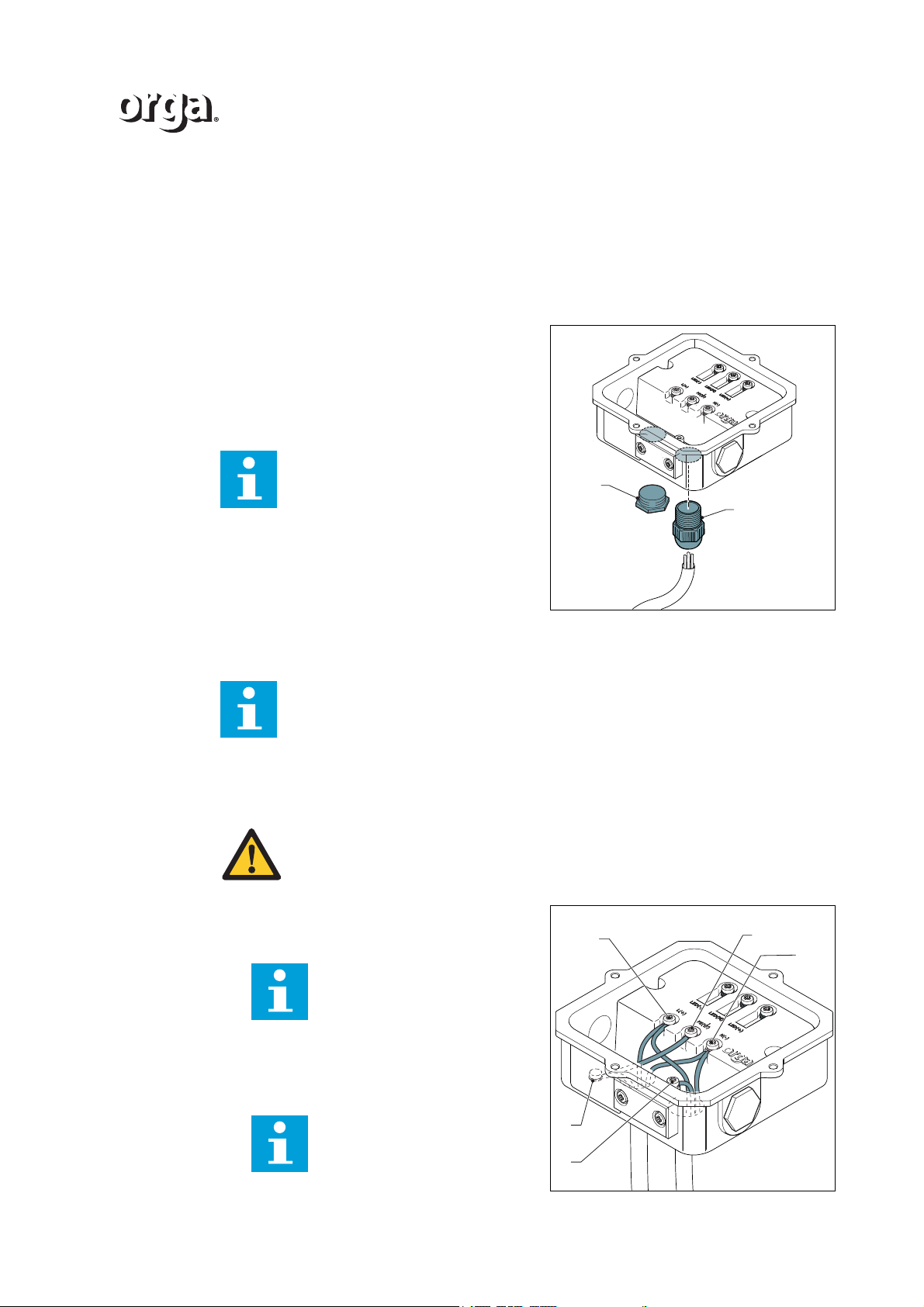
1.5 Installation of L85EX Recessed
A
B
N(-)
PE
L(+)
A
B
1.5.1 Open the cover assembly
1. Open the cover assembly. Refer to section 2.3.
1.5.2 Connect the power supply cable
1. Fasten the power supply cable with the
cable gland (A)
2. Close the second cable entry with a blind
plug (B).
3. Connect the cable to the control panel (not
included).
Note
For looping (daisy chaining), use
two power supply cables and two
cable glands.
INSTALLATION
1.5.3 Connect the wiring of the lighting fixture
Note
The procedure below applies to each lighting fixture on the platform.
Looping of the lighting fixture
WARNING
Only use cable lugs of the eyelet type.
1. Connect the live wire of the cables with
terminal L. Apply a torque of minimum
0.75 and maximum 1.25 Nm.
Note
In case of a DC execution, connect the (+) wire to the (+) terminal.
2. Connect the neutral wire of the cables with
terminal N. Apply a torque of minimum
0.75 and maximum 1.25 Nm.
Note
In case of a DC execution, connect the (-) wire to the (-) terminal.
Version 2.1 19
Page 20
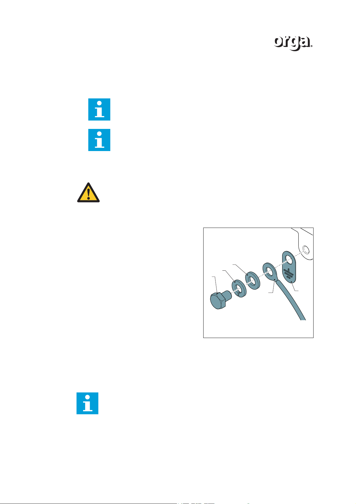
INSTALLATION
D
A
B
C
E
3. Connect the earth wire of the cables to the earth connection (A) in the housing. Apply
a torque of minimum 0.75 and maximum 1.25 Nm.
4. When looping the lighting fixture, connect terminal (PE) to the earth connection (B) in
the housing. Apply a torque of minimum 0.75 and maximum 1.25 Nm.
External earth connection
Note
The internal earth wire is already connected.
Note
Connect the looping cable with cable lugs of the eyelet type. Use one eyelet cable lug for each earth connection.
WARNING
Make sure that the external earth connection on the platform is located within
30 centimetres of the light fixture:
- to prevent loosening;
- to prevent twists.
1. Connect the metric M6 connection on the
foot of the base with an earth cable
mounting bolt (A) to a grounded structure
on the platform.
- Place the earthing tag (E) on the
base.
- Use a PE wire with a cross-sectional
area of at least 4 mm
cable lug (D).
- Use a M6 earth cable mounting bolt
(A) in combination with the provided
spring lock washer (B) and washer
(C).
2
with a supplied
1.5.4 Close the cover assembly
1. Close the cover assembly. Refer to section 2.4.
1.5.5 Install the light fixture
Note
• The light fixture must be installed on a rigid, horizontal surface, in a posi-
tion that meets the specific visibility requirements.
• Keep sufficient open space around the light fixture for maintenance pur-
Orga advises to install the light fixture according to the procedure below:
poses.
20 Version 2.1
Page 21
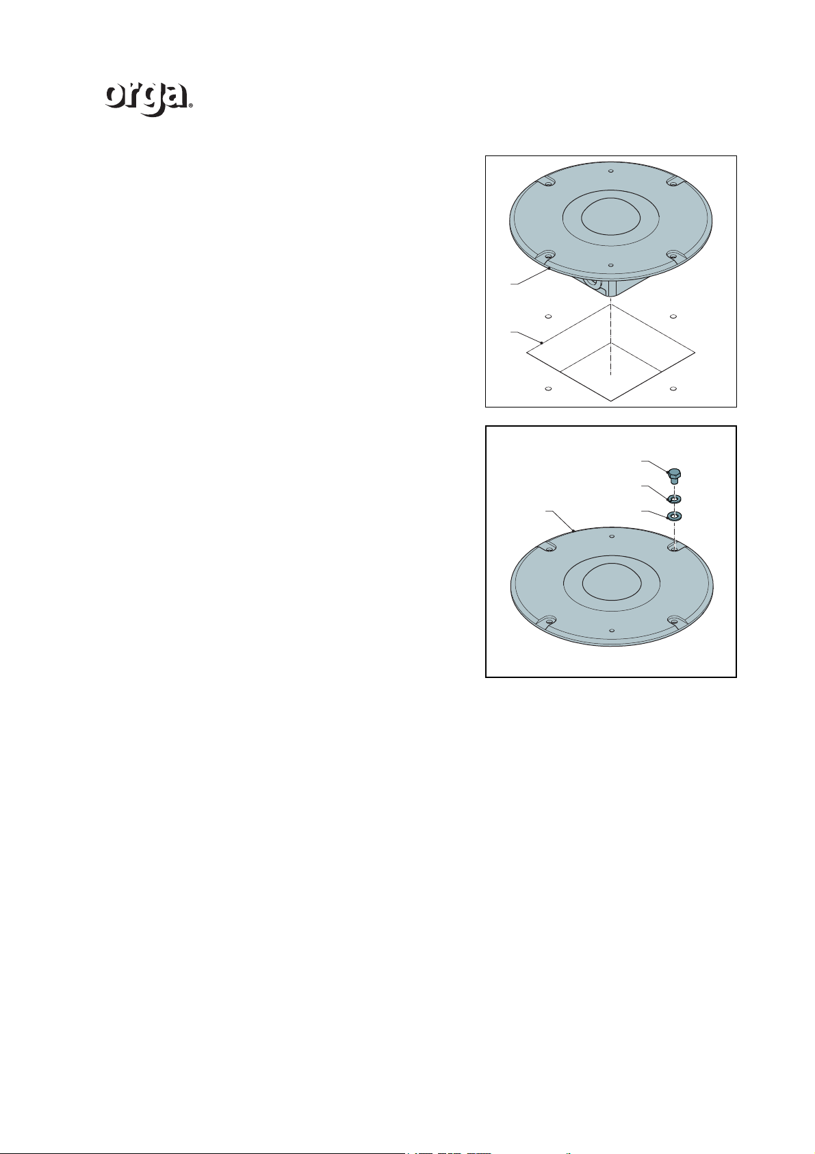
1. Install the light fixture (A) in the cavity (B)
A
B
A D
C
B
with the cables. For a specification of the
cavity sizes, refer to 5.3.1.
2. Fasten the cover assembly (A) to the
surface with M8 fasteners (B), a suitable
spring lock washer (C) and washer (D).
3. Make sure that the light fixture is
horizontally levelled. Use a spirit level
device.
INSTALLATION
Version 2.1 21
Page 22

INSTALLATION
22 Version 2.1
Page 23
2 ACCESS TO PARTS
CAB
BC
A
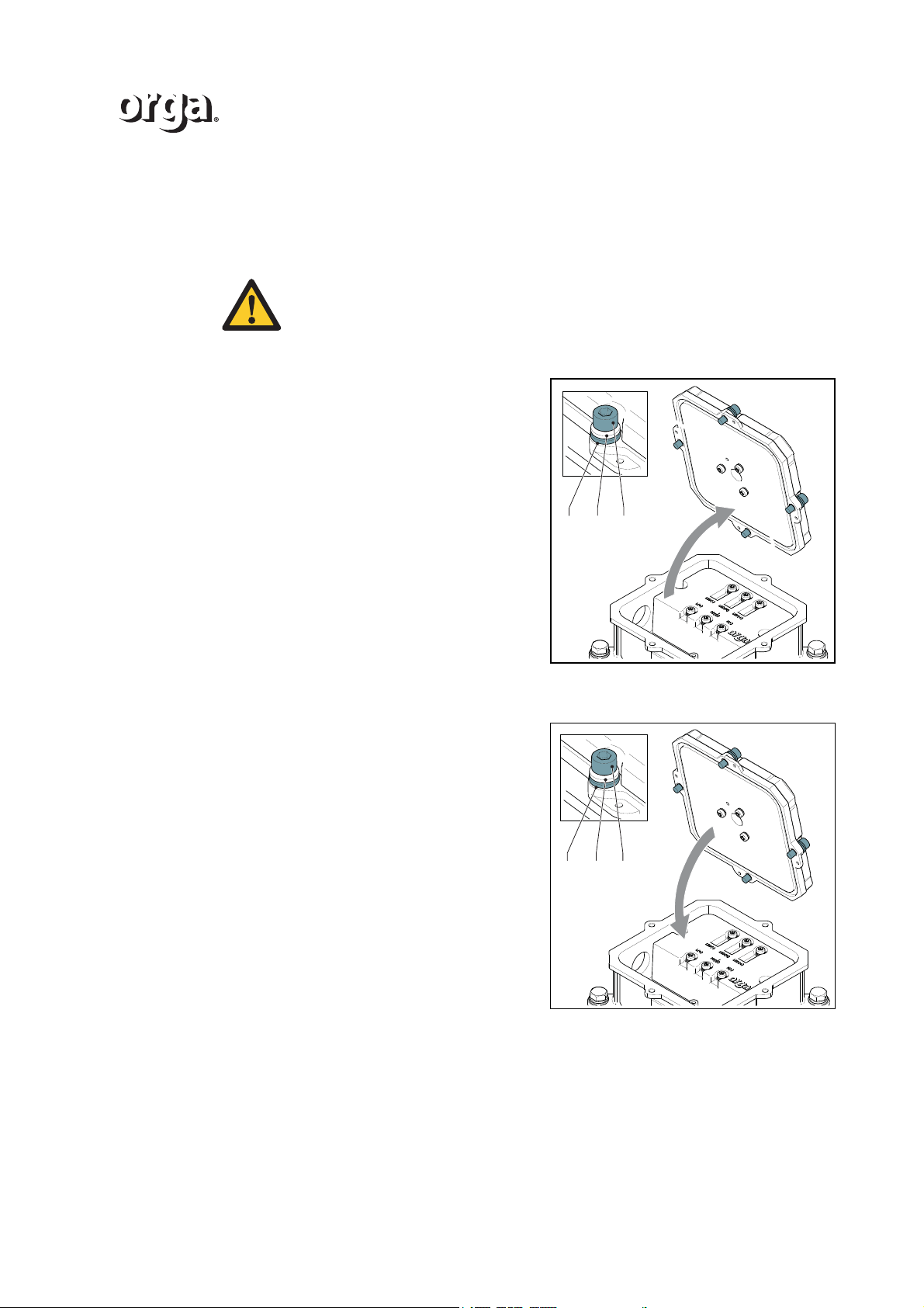
2.1 Open the cover assembly
WARNING
Make sure that the equipment is de-energized:
1 On the control panel, turn the mains power switch to the OFF position.
2 Switch off the mains power supply.
1. Loosen the four bolts (A) and the washers
(B) and (C).
2. Open the cover assembly.
ACCESS TO PARTS
2.2 Close the cover assembly
1. Close the cover assembly.
2. Tighten the four bolts (A) and the washers
(B) and (C) with a torque of minimum 2.5
Nm and maximum 3.5 Nm.
3. On the control panel, turn the mains
power switch to the ON position.
4. Switch on the (mains) power supply.
5. Do a function test.
Version 2.1 23
Page 24
ACCESS TO PARTS
E
D
C
B
A
E
D
C
B
A
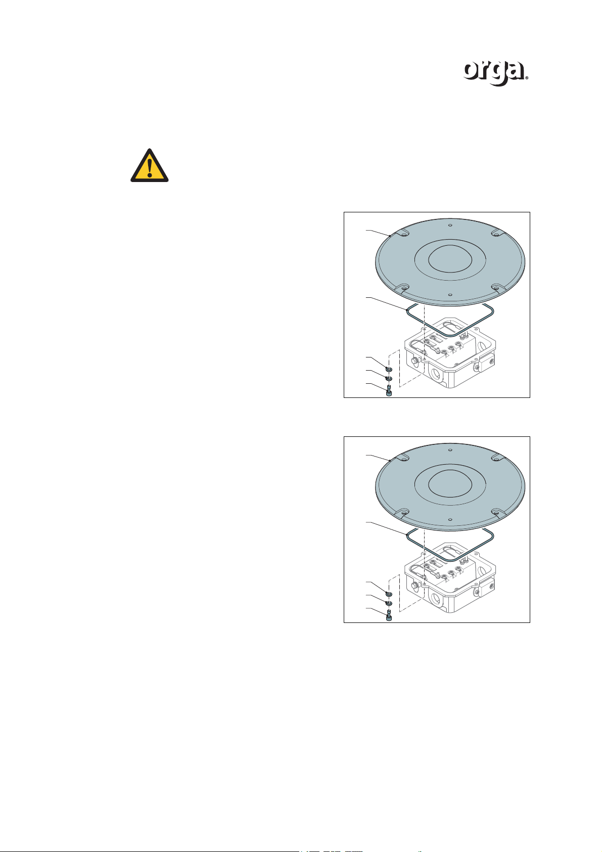
2.3 Open the cover assembly of the recessed version
WARNING
Make sure that the equipment is de-energized:
1 On the control panel, turn the mains power switch to the OFF position.
2 Switch off the mains power supply.
1. Remove the four bolts (A) and the
washers (B) and (C).
2. Open the cover assembly (E).
3. Remove the seal (D) with the cover.
2.4 Close the cover assembly of the recessed version
1. Close the cover assembly (E) with the
seal (D).
2. Install the four bolts (A) with the washers
(B) and (C). Apply a torque of minimum
2.5 and maximum 3.5 Nm.
24 Version 2.1
Page 25
3 MAINTENANCE
3.1 Advised maintenance schedule
WARNING
Only an electrical engineer is allowed to do maintenance on the electrical
system.
System unit Task Limit Step
Domes Visual inspection on con-
tamination
MAINTENANCE
Every 12 months Clean. Refer to 3.2.1.
Visual inspection on
scratches and other damage
Base Visual inspection of the
coating on damage and
corrosion
External earth
connection
Fixing bolts and
nuts of the entire
lantern
Lighting fixture Inspect the electrical con-
Central control
panel
Visual inspection on correct fastening
Visual inspection on correct fastening
nections
Failure of the lantern could
result in an alarm message
at the central control panel.
3.2 Maintenance procedures
CAUTION
For cleaning:
• Always use a damp cloth or fresh water to prevent potential electrostatic
charging hazards.
• Never use solvents of any kind.
Every 12 months Contact Orga.
Every 12 months Contact Orga.
Every 12 months Correct the fastening.
Refer to 1.4.4.
Every 12 months Correct the fastening.
Refer to 1.4.1.
Every 12 months Refer to 4.2.1, 4.2.2.
In case of alarm messages, see the instructions of the central control
panel.
3.2.1 Clean the dome(s)
1. Clean the dome(s). Use a damp cloth or fresh water and a mild cleaning detergent to
prevent potential electrostatic charging hazards.
Version 2.1 25
Page 26

MAINTENANCE
26 Version 2.1
Page 27
4 TROUBLESHOOTING
4.1 Failure of the light fixture
The table below gives the possible problems and its solution.
If the problem is not listed below, contact Orga BV.
WARNING
Only an electrical engineer is allowed to do maintenance on the electrical
system.
Problem Possible cause Solution
The light is off Failure at the power supply. Make sure that the power sup-
Bad connection of the wiring Check the internal connections
Power failure Check the power supply cable
Defective LED(s) Contact Orga.
TROUBLESHOOTING
ply to the control panel is energized.
Check the alarm messages on
the control panel. See the
instructions in the control panel.
Refer to 4.2.
on both sides. Refer to 4.2.2.
Wire breakage Check the internal connections
Refer to 4.2.
Unknown If you cannot solve the problem,
contact Orga.
Version 2.1 27
Page 28
TROUBLESHOOTING
4.2 Check the electrical connections
WARNING
Only an electrical engineer is allowed to do maintenance on the electrical
system.
CAUTION
Use proper tooling to prevent damage on the material that is installed.
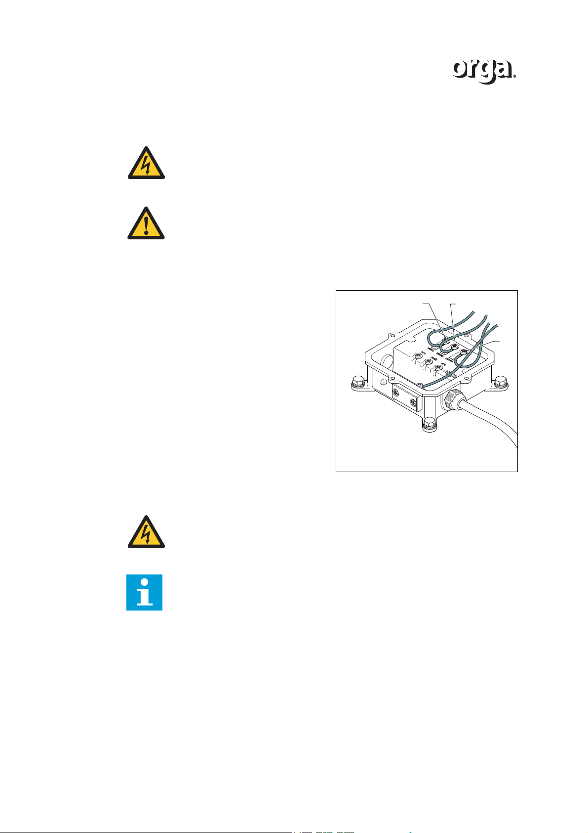
4.2.1 Check the internal connections (control unit to LEDs)
1. Open the cover assembly, see section 2.
2. Check if the internal connections of the
control unit to the lamp are tight:
-
• Connection to terminal LED (-).
• Mid connection M.
• Connection to terminal LED (+).
3. If necessary, correct the connections.
Apply a torque of minimum 0.75 Nm and
maximum 1.25 Nm on the bolts.
4. Close the cover assembly, see section 2.
4.2.2 Check the power supply (control panel to control unit)
WARNING
Only an electrical engineer is allowed to do maintenance on the electrical
system.
m
+
Note
Check the cable connections of both cables between the lighting fixtures.
28 Version 2.1
Page 29
TROUBLESHOOTING
N(-)
PE
L(+)
A
B
+
m
-
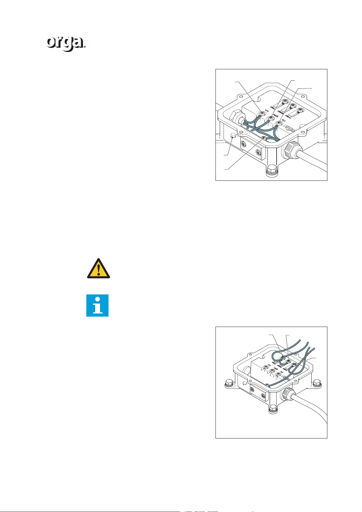
1. Open the cover assembly, see section 2.
2. Check if the electrical connections in the
housing are tight.
• Connection to terminal L (+).
• Earth connection PE.
• Connection to terminal N (-).
• Earth connection (A) in the housing.
3. If necessary, correct the connection(s).
4. Switch on the mains power supply.
5. Check if the LED’s function.
• If yes, switch off the power supply and
close the lighting fixture.
• If not, check the power supply from
the control panel.
6. On the control panel, turn the mains power switch to the ON position.
7. Check if the LED’s function.
• If yes, switch off the power and close the lighting fixture.
• If not, replace the control unit.
8. Close the cover assembly, see section 2.
4.3 Replace the dome
WARNING
Only use cable lugs of the eyelet type.
Note
Do not strip the insulation of the wiring more than is necessary.
1. Connect the live wire from the cover
assembly with terminal -. Apply a torque of
minimum 0.75 and maximum 1.25 Nm.
2. Connect the neutral wire with terminal +.
Apply a torque of minimum 0.75 and
maximum 1.25 Nm.
3. Connect the earth wire with terminal M.
Apply a torque of minimum 0.75 and
maximum 1.25 Nm.
4. Connect the second earth wire (A) to the
earth connection (B).
5. Close the lighting fixture. Refer to 2.
Version 2.1 29
Page 30

TROUBLESHOOTING
30 Version 2.1
Page 31
5TECHNICAL DATA
5.1 Mechanical specification
5.1.1 Perimeter light L85EX-G-AC
Explosion proof LED perimeter light
/i
Table 1 Standards and certification
Standards/Certification Certified to CAA-UK CAP 437; Offshore helicopter landing areas -
Guidance on standards, 7th edition, chapter 4, paragraph 3.1
Certified to IMO standard MODU code; 2009 (Edition 2010), chapter 13.5.21
Certified to with ICAO Annex 14,International standards and recommended practices:Aerodromes, Volume ll -Heliports; 4th edition, July 2013, chapter 5.3.9
Cenelec EN 60079-0, EN 60079-7 and EN 60079-18
SIRA 12ATEX3066 X; ATEX II 2G Ex e mb IIC T4 Gb
IEC 60079-0, IEC 60079-7 and IEC 60079-18
IECEx SIR 12.0026 X; Ex e mb IIC T4 Gb
TECHNICAL DATA
NCC 12.1223; Ex e mb IIC T4 Gb
/i
Table 2 Performance characteristics
LED Steady burning ; green
Intensity 30 cd (60 cd maximum)
Horizontal beam coverage 360º
Vertical beam profile As per CAP437 table
Colour chromaticity Within the boundaries as specified by ICAO
Light source LED (100,000 hours average life)
/i
Table 3 Electrical characteristics
Operating voltage 100-254 Vac;50-60 Hz
Power consumption 4.5 W (6 VA)
Connection details M4; two M25x1.5 cable entries
Earth connection Internal M4 and external M6
/i
Version 2.1 31
Page 32

TECHNICAL DATA
Table 4 Physical characteristics
Dimensions (L x W x H) 161 x 161 x 111 mm
Weight 3.6 kg
Design degree of protection IP66
Operating temperature range
ATEX/IECEx
-40 ºC to +60 ºC
Operating temperature range
Inmetro
-50 ºC to +45 ºC
32 Version 2.1
Page 33
5.1.2 Perimeter light L85EX-G-AC-RE
Explosion proof LED Perimeter light.
/i
Table 5 Standards and certification
Standards/Certification Certified to CAA-UK CAP 437;Offshore helicopter landing areas -
Guidance on standards,7th edition, chapter 4,paragraph 3.1
Certified to IMO standard MODU code; 2009 (Edition 2010),chapter 13.5.21
Certified to ICAO Annex 14,International standards and recommended practices: Aerodromes, Volume ll -Heliports; 4th edition,
July 2013, chapter 5.3.9t
Cenelec EN 60079-0, EN 60079-7 and EN 60079-18
SIRA 12ATEX3066; ATEX II 2G Ex e mb IIC T4 Gb
IEC 60079-0, IEC 60079-7 and IEC 60079-18
IECEx SIR 12.0026; Ex e mb IIC T4 Gb
NCC 12.1223; Ex e mb IIC T4 Gb
/i
Table 6 Performance characteristics
TECHNICAL DATA
LED Steady burning; green
Intensity Minimum 30 cd (60 cd maximum
Horizontal beam coverage 360º
Vertical beam profile As per CAP437 table
Colour chromaticity Within the boundaries as specified by ICAO
Light source LED (100,000 hours average life)
/i
Table 7 Electrical characteristics
Operating voltage 100-254 Vac; 50-60 Hz
Power consumption Approx. 4.5 W (6 VA)
Connection details M4; two M25x1.5 cable entries
Earth connection Internal M4 and external M6
/i
Table 8 Physical characteristics
Dimensions (∅ x H) ∅ 298 x 111mm
Weight 9.1 kg
Degree of protection IP66
Operating temperature range
ATEX/IECEx
Operating temperature range
Inmetro
-40 ºC to +60 ºC
-50 ºC to +45 ºC
Version 2.1 33
Page 34
TECHNICAL DATA
5.1.3 Aeronautical obstruction light L85EX-R-AC-10
Explosion proof LED aeronautical obstruction light.
/i
Table 9 Standards and certification
Standards/Certification Certified to ICAO Annex 14, volume l; 5th Edition, November2009,
chapter 6.3.2 – Type A low intensity obstacle light
Certified to IMO standard MODU code; 2009 (Edition 2010),chapter 13.5.24
Certified to CAA-UK CAP 437;Offshore helicopter landing areas Guidance on standards,7TH edition, chapter 4,paragraph 4.3
Complies with CAA-UK CAP 168; July 2010, chapter 4,
paragraph12.8.1a, 12.10.2, 12.11.3 and table 6A.1.11 – Low intensity aeronautical obstruction light -Group A
Certified to Mining regulations of The Netherlands 2003, - Article
5.5
Certified to German "General Administrative Regulation for the
marking and lighting of obstacles to air avigation" Low Intensity
Type A / Hindernisfeuer
Cenelec EN 60079-0, EN 60079-7 and EN 60079-18
SIRA 12ATEX3066 X; ATEX II 2G Ex e mb IIC T4 Gb
IEC 60079-0, IEC 60079-7 and IEC 60079-18
IECEx SIR 12.0026; Ex e mb IIC T4 Gb
NCC 12.1223; Ex e mb IIC T4 Gb
/i
Table 10 Performance characteristics
LED Steady burning; red
Intensity Minimum 10 cd
Horizontal beam coverage 360º
Vertical beam profile Visible from any point above the horizon
Colour chromaticity Within the boundaries as specified by ICAO
Light source LED (100,000 hours average life)
/i
Table 11 Electrical characteristics
Operating voltage 100-254 Vac; 50-60 Hz
Power consumption Approx. 2.5 W (4 VA)
Connection details M4; two M25x1.5 cable entries
Earth connection Internal M4 and external M6
/i
34 Version 2.1
Page 35

Table 12 Physical characteristics
Dimensions (L x W x H) 161 x 161 x 111 mm
Weight 3.6 kg
Degree of protection IP66
Operating temperature range
ATEX/IECEx
-40 ºC to +60 ºC
TECHNICAL DATA
Operating temperature range
Inmetro
-50 ºC to +45 ºC
Version 2.1 35
Page 36
TECHNICAL DATA
5.1.4 Aeronautical obstruction light L85EX-R-AC-32
Explosion proof LED aeronautical obstruction light.
/i
Table 13 Standards and certification
Standards/Certification Certified to ICAO Annex 14, volume l; : Aerodrome design and
operation, 6th Edition, 2013, chapter 6.3.2 - Type B low intensity
obstacle light
Certified to IMO standard, MODU code 2009 (Edition 2010) , chapter 13.5.24
Cenelec EN 60079-0, EN 60079-7 and EN 60079-18
SIRA 12ATEX3066 X; ATEX II 2G Ex e mb IIC T4 Gb
IEC 60079-0, IEC 60079-7 and IEC 60079-18
IECEx SIR 12.0026 X; Ex e mb IIC T4 Gb
NCC 12.1223; Ex e mb IIC T4 Gb
/i
Table 14 Performance characteristics
LED Steady burning; red
Intensity Minimum 32 cd
Horizontal beam coverage 360º
Vertical beam profile As per ICAO
Colour chromaticity Within the boundaries as specified by ICAO
Light source LED (100,000 hours average life)
/i
Table 15 Electrical characteristics
Operating voltage 100-254 Vac; 50-60 Hz
Power consumption Approx. 5.5 W (7 VA)
Connection details M4; two M25x1.5 cable entries
Earth connection Internal M4 and external M6
/i
Table 16 Physical characteristics
Dimensions (L x W x H) 161 x 161 x 111 mm
Weight 3.6 kg
Degree of protection IP66
Operating temperature range
ATEX/IECEx
Operating temperature range
Inmetro
-40 ºC to +60 ºC
-50 ºC to +45 ºC
36 Version 2.1
Page 37
5.1.5 Aeronautical obstruction light L85EX-R-AC-50
Explosion proof LED aeronautical obstruction light.
/i
Table 17 Standards and certification
Standards/Certification Cenelec EN 60079-0, EN 60079-7 and EN 60079-18
SIRA 12ATEX3066 X; ATEX II 2G Ex e mb IIC T4 Gb
IEC 60079-0, IEC 60079-7 and IEC 60079-18
IECEx SIR 12.0026 X; Ex e mb IIC T4 Gb
NCC 12.1223; Ex e mb IIC T4 Gb
/i
Table 18 Performance characteristics
LED Steady burning; red
Intensity 50 cd
Horizontal beam coverage 360º
Vertical beam profile Visible from any point above the horizon
Light source LED (100,000 hours average life)
TECHNICAL DATA
Colour chromaticity Within the boundaries as specified by ICAO
/i
Table 19 Electrical characteristics
Operating voltage 100-254 Vac; 50-60 Hz
Power consumption Approx. 8 W (9 VA)
Connection details M4; two M25x1.5 cable entries
Earth connection internal M4 and external M6
/i
Table 20 Physical characteristics
Dimensions (L x W x H) 161 x 161 x 111 mm
Weight 3.6 kg
Degree of protection IP66
Operating temperature range
ATEX/IECEx
Operating temperature range
Inmetro
-40 ºC to +55 ºC
-50 ºC to +40 ºC
Version 2.1 37
Page 38
TECHNICAL DATA
5.1.6 Aeronautical obstruction light L85EX-R-AC-200
Explosion proof LED aeronautical obstruction light.
/i
Table 21 Standards and certification
Standards/Certification Complies with CAA-UK CAP 437;Offshore helicopter landing
areas - Guidance on standards, 7th edition Feb 2013, chapter
4,paragraph 4.4
Cenelec EN 60079-0, EN 60079-7 and EN 60079-18
SIRA 12ATEX3066 X; ATEX II 2G Ex e mb IIC T4 Gb
IEC 60079-0, IEC 60079-7 and IEC 60079-18
IECEx SIR 12.0026 X; Ex e mb IIC T4 Gb
NCC 12.1223; Ex e mb IIC T4 Gb
/i
Table 22 Performance characteristics
LED Steady burning; red
Intensity 200cd minimum (between 5° - 8°)
and 50cd minimum (between 0° - 15°)
Horizontal beam coverage 360º
Vertical beam profile: As per CAP168 Chapter 4 and Appendix 6,Table 6A.1, Group B
Light source LED (100,000 hours average life)
Colour chromaticity Within the boundaries as specified by ICAO
/i
Table 23 Electrical characteristics
Operating voltage 100-254 Vac; 50-60 Hz
Power consumption Approx. 8 W (9 VA)
Connection details M4; two M25x1.5 cable entries
Earth connection Internal M4 and external M6
/i
Table 24 Physical characteristics
Dimensions (L x W x H) 161 x 161 x 111 mm
Weight 3.6 kg
Degree of protection IP66
Operating temperature range
ATEX/IECEx
Operating temperature range
Inmetro
-40 ºC to +55 ºC
-50 ºC to +40 ºC
38 Version 2.1
Page 39
5.1.7 Perimeter light L85EX-B-AC
Explosion proof LED perimeter light
/i
Table 25 Standards and certification
Standards/Certification In line with API (American Petroleum Institute), Recommended
practice for Planning, Designing, and Constructing Heliports for
Fixed Offshore Platforms; RP 2L, 1996, chapter 5.10
In line with API (American Petroleum Institute), Recommended
practice for Design and Installation of Electrical Systems for Fixed
and Floating Offshore Petroleum Facilities for Unclassified and
Class 1, Zone 0, Zone 1 and Zone 2 Locations; RP 14FZ, 2001,
chapter 9.5.6
Cenelec EN 60079-0, EN 60079-7 and EN 60079-18
SIRA 12ATEX3066 X; ATEX II 2G Ex e mb IIC T4 Gb
IEC 60079-0, IEC 60079-7 and IEC 60079-18
IECEx SIR 12.0026 X; Ex e mb IIC T4 Gb
NCC 12.1223; Ex e mb IIC T4 Gb
TECHNICAL DATA
/i
Table 26 Performance characteristics
LED Steady burning; blue
Intensity 10 cd
Horizontal beam coverage 360º
Light source LED (100,000 hours average life)
Colour chromaticity Within the boundaries as specified by ICAO
/i
Table 27 Electrical characteristics
Operating voltage 100-254 Vac; 50-60 Hz
Power consumption 4.5 W (6 VA)
Connection details M4; two M25x1.5 cable entries
Earth connection Internal M4 and external M6
/i
Table 28 Physical characteristics
Dimensions (L x W x H) 161 x 161 x 111 mm
Weight 3.6 kg
Design degree of protection IP66
Operating temperature range
ATEX/IECEx
-40 ºC to +60 ºC
Operating temperature range
-50 ºC to +45 ºC
Inmetro
Version 2.1 39
Page 40

TECHNICAL DATA
5.1.8 Perimeter light L85EX-Y-AC
Explosion proof LED perimeter light
/i
Table 29 Standards and certification
Standards/Certification In line with API (American Petroleum Institute), Recommended
practice for Planning, Designing, and Constructing Heliports for
Fixed Offshore Platforms; RP 2L, 1996, chapter 5.10
In line with API (American Petroleum Institute), Recommended
practice for Design and Installation of Electrical Systems for Fixed
and Floating Offshore Petroleum Facilities for Unclassified and
Class 1, Zone 0, Zone 1 and Zone 2 Locations; RP 14FZ, 2001,
chapter 9.5.6
Cenelec EN 60079-0, EN 60079-7 and EN 60079-18
SIRA 12ATEX3066 X; ATEX II 2G Ex e mb IIC T4 Gb
IEC 60079-0, IEC 60079-7 and IEC 60079-18
IECEx SIR 12.0026 X; Ex e mb IIC T4 Gb
NCC 12.1223; Ex e mb IIC T4 Gb
/i
Table 30 Performance characteristics
LED Steady burning; yellow
Intensity 10 cd
Horizontal beam coverage 360º
Light source LED (100,000 hours average life)
Colour chromaticity Within the boundaries as specified by ICAO
/i
Table 31 Electrical characteristics
Operating voltage 100-254 Vac; 50-60 Hz
Power consumption 2.5 W (4 VA)
Connection details M4; two M25x1.5 cable entries
Earth connection Internal M4 and external M6
/i
Table 32 Physical characteristics
Dimensions (L x W x H) 161 x 161 x 96 mm
Weight 3.6 kg
Design degree of protection IP66
Operating temperature range
ATEX/IECEx
-40 ºC to +60 ºC
Operating temperature range
-50 ºC to +45 ºC
Inmetro
40 Version 2.1
Page 41
5.1.9 Perimeter light L85EX-G-DC
Explosion proof LED perimeter light
/i
Table 33 Standards and certification
Standards/Certification Certified to CAA-UK CAP 437;Offshore helicopter landing areas -
Guidance on standards,7th edition, chapter 4,paragraph 3.1
Certified to IMO standard MODU code; 2009 (Edition 2010),chapter 13.5.21
Certified to ICAO Annex 14,International standards and recommended practices: Aerodromes, Volume ll - Heliports; 4th edition,
July 2013, chapter 5.3.9
Cenelec EN 60079-0, EN 60079-7 and EN 60079-18
SIRA 12ATEX3066 ; ATEX II 2G Ex e mb IIC T4 Gb
IEC 60079-0, IEC 60079-7 and IEC 60079-18
IECEx SIR 12.0026 ; Ex e mb IIC T4 Gb
NCC 12.1223; Ex e mb IIC T4 Gb
/i
Table 34 Performance characteristics
TECHNICAL DATA
LED Steady burning; green
Intensity 30cd (60cd maximum)
Horizontal beam coverage 360º
Vertical beam profile As per CAP437 table
Light source LED (100,000 hours average life)
Colour chromaticity Within the boundaries as specified by ICAO
/i
Table 35 Electrical characteristics
Operating voltage 20-30 Vdc
Power consumption 4 W
Connection details M4; two M25x1.5 cable entries
Earth connection Internal M4 and external M6
/i
Table 36 Physical characteristics
Dimensions (L x W x H) 161 x 161 x 111 mm
Weight 3.6 kg
Design degree of protection IP66
Operating temperature range
ATEX/IECEx
Operating temperature range
Inmetro
-40 ºC to +60 ºC
-50 ºC to +45 ºC
Version 2.1 41
Page 42
TECHNICAL DATA
5.1.10 Perimeter light L85EX-G-DC-RE
Explosion proof LED perimeter light
/i
Table 37 Standards and certification
Standards/Certification Certified to CAA-UK CAP 437;Offshore helicopter landing areas -
Guidance on standards, 7th edition, chapter 4,paragraph 3.1
Certified to IMO standard MODU code; 2009 (Edition 2010),chapter 13.5.21
Certified to ICAO Annex 14, International standards and recommended practices: Aerodromes, Volume ll - Heliports; 4th edition,
July 2013, chapter 5.3.9
Cenelec EN 60079-0, EN 60079-7 and EN 60079-18
SIRA 12ATEX3066 ; ATEX II 2G Ex e mb IIC T4 Gb
IEC 60079-0, IEC 60079-7 and IEC 60079-18
IECEx SIR 12.0026 ; Ex e mb IIC T4 Gb
NCC 12.1223; Ex e mb IIC T4 Gb
/i
Table 38 Performance characteristics
LED Steady burning; green
Intensity 30cd (60cd maximum)
Horizontal beam coverage 360º
Vertical beam profile As per CAP437 table
Light source LED (100,000 hours average life)
Colour chromaticity Within the boundaries as specified by ICAO
/i
Table 39 Electrical characteristics
Operating voltage 20-30 Vdc
Power consumption 4 W
Connection details M4; two M25x1.5 cable entries
Earth connection Internal M4 and external M6
/i
Table 40 Physical characteristics
Dimensions (L x W x H) 161 x 161 x 111 mm
Weight 3.6 kg
Design degree of protection IP66
Operating temperature range
ATEX/IECEx
Operating temperature range
Inmetro
-40 ºC to +60 ºC
-50 ºC to +45 ºC
42 Version 2.1
Page 43
5.1.11 Aeronautical obstruction light L85EX-R-DC-10
Explosion proof LED aeronautical obstruction light.
/i
Table 41 Standards and certification
Standards/Certification Certified to ICAO Annex 14,volume l; Aerodrome design andoper-
ations, 6th Edition, 2013, chapter 6.3.2 - Type A low intensity
obstacle light
Certified to IMO standard MODU code; 2009 (Edition 2010),chapter 13.5.24
Certified to CAA-UK CAP 437;Offshore helicopter landingareas Guidance on standards, 7th edition, chapter 4,paragraph 4.3
Complies with CAA-UK CAP 168;July 2010, chapter 4,
paragraph12.8.1a, 12.10.2, 12.11.3 and table 6A.1.11 – Low intensityaeronautical obstruction light Group A
Certified to Mining regulations of the Netherlands; 2002,article 5.5
Certified to German "General Administrative Regulation for the
marking and lighting of obstacles to air avigation" Low Intensity
Type A / Hindernisfeuer
TECHNICAL DATA
Cenelec EN 60079-0, EN 60079-7 and EN 60079-18
SIRA 12ATEX3066; ATEX II 2G Ex e mb IIC T4 Gb
IEC 60079-0, IEC 60079-7 and IEC 60079-18
IECEx SIR 12.0026 X; Ex e mb IIC T4 Gb
NCC 12.1223; Ex e mb IIC T4 Gb
/i
Table 42 Performance characteristics
LED Steady burning; red
Intensity 10 cd
Horizontal beam coverage 360º
Vertical beam profile: Visible from any point above the horizon
Light source LED (100,000 hours average life)
Colour chromaticity Within the boundaries as specified by ICAO
/i
Table 43 Electrical characteristics
Operating voltage 20 - 30 Vdc
Power consumption 2 W
Connection details M4; two M25x1.5 cable entries
Earth connection Internal M4 and external M6
/i
Version 2.1 43
Page 44

TECHNICAL DATA
Table 44 Physical characteristics
Dimensions (L x W x H) 161 x 161 x 111 mm
Weight 3.6 kg
Degree of protection IP66
Operating temperature range
ATEX/IECEx
-40 ºC to +60 ºC
Operating temperature range
Inmetro
-50 ºC to +45 ºC
44 Version 2.1
Page 45
5.1.12 Aeronautical obstruction light L85EX-R-DC-32
Explosion proof LED aeronautical obstruction light.
/i
Table 45 Standards and certification
Standards/Certification operations, 6th Edition, 2013, chapter 6.3.2 - Type B low intensity
obstacle light
Certified to IMO standard, MODU code; 2009 (Edition 2010),
chapter 13.5.24
Cenelec EN 60079-0, EN 60079-7 and EN 60079-18
SIRA 12ATEX3066 ; ATEX II 2G Ex e mb IIC T4 Gb
IEC 60079-0, IEC 60079-7 and IEC 60079-18
IECEx SIR 12.0026 X; Ex e mb IIC T4 Gb
NCC 12.1223; Ex e mb IIC T4 Gb
/i
Table 46 Performance characteristics
LED Steady burning; red
Intensity 32cd minimum (all angles above horizon)
Horizontal beam coverage 360º
TECHNICAL DATA
Vertical beam profile: As per ICAO
Light source LED (100,000 hours average life)
Colour chromaticity Within the boundaries as specified by ICAO
/i
Table 47 Electrical characteristics
Operating voltage 20 - 30 Vdc
Power consumption 5 W
Connection details M4; two M25x1.5 cable entries
Earth connection Internal M4 and external M6
/i
Table 48 Physical characteristics
Dimensions (L x W x H) 161 x 161 x 111 mm
Weight 3.6 kg
Degree of protection IP66
Operating temperature range
ATEX/IECEx
Operating temperature range
Inmetro
-40 ºC to +60 ºC
-50 ºC to +45 ºC
Version 2.1 45
Page 46
TECHNICAL DATA
5.1.13 Aeronautical obstruction light L85EX-R-DC-50
Explosion proof LED aeronautical obstruction light.
/i
Table 49 Standards and certification
Standards/Certification Cenelec EN 60079-0, EN 60079-7 and EN 60079-18
SIRA 12ATEX3066 X; ATEX II 2G Ex e mb IIC T4 Gb
IEC 60079-0, IEC 60079-7 and IEC 60079-18
IECEx SIR 12.0026 X; Ex e mb IIC T4 Gb
NCC 12.1223; Ex e mb IIC T4 Gb
/i
Table 50 Performance characteristics
LED Steady burning; red
Intensity 50cd
Horizontal beam coverage 360º
Vertical beam profile: Visible from any point above the horizon
Light source LED (100,000 hours average life)
Colour chromaticity Within the boundaries as specified by ICAO
/i
Table 51 Electrical characteristics
Operating voltage 20 - 30 Vdc
Power consumption Approx. 7,5 W
Connection details M4; two M25x1.5 cable entries
Earth connection Internal M4 and external M6
/i
Table 52 Physical characteristics
Dimensions (L x W x H) 161 x 161 x 111 mm
Weight 3.6 kg
Degree of protection IP66
Operating temperature range
ATEX/IECEx
Operating temperature range
Inmetro
-40 ºC to +55 ºC
-50 ºC to +40 ºC
46 Version 2.1
Page 47
5.1.14 Aeronautical obstruction light L85EX-R-DC-200
Explosion proof LED aeronautical obstruction light.
/i
Table 53 Standards and certification
Standards/Certification Complies with CAA-UK CAP 437;Offshore helicopter landing
areas - Guidance on standards, 7th edition Feb 2013, chapter
4,paragraph 4.4
Cenelec EN 60079-0, EN 60079-7 and EN 60079-18
SIRA 12ATEX3066 X; ATEX II 2G Ex e mb IIC T4 Gb
IEC 60079-0, IEC 60079-7 and IEC 60079-18
IECEx SIR 12.0026 ; Ex e mb IIC T4 Gb
NCC 12.1223; Ex e mb IIC T4 Gb
/i
Table 54 Performance characteristics
LED Steady burning; red
Intensity 200cd minimum (between 5° - 8°) and
50cd minimum (between 0° - 15°)
Horizontal beam coverage 360º
Vertical beam profile: As per CAP168 Chapter 4 and Appendix 6,Table 6A.1, Group B
TECHNICAL DATA
Light source LED (100,000 hours average life)
Colour chromaticity Within the boundaries as specified by ICAO
/i
Table 55 Electrical characteristics
Operating voltage 20-30 Vdc
Power consumption Approx. 7,5 W
Connection details M4; two M25x1.5 cable entries
/i
Table 56 Physical characteristics
Dimensions (L x W x H) 161 x 161 x 111 mm
Weight 3.6 kg
Degree of protection IP66
Operating temperature range
ATEX/IECEx
Operating temperature range
Inmetro
-40 ºC to +55 ºC
-50 ºC to +45 ºC
Version 2.1 47
Page 48
TECHNICAL DATA
5.1.15 Perimeter light L85EX-B-DC
Explosion proof LED perimeter light
/i
Table 57 Standards and certification
Standards/Certification In line with API (American Petroleum Institute), Recommended
practice for Planning, Designing, and Constructing Heliports for
Fixed Offshore Platforms; RP 2L, 1996, chapter 5.10
In line with API (American Petroleum Institute), Recommended
practice for Design and Installation of Electrical Systems for Fixed
and Floating Offshore Petroleum Facilities for Unclassified and
Class 1, Zone 0, Zone 1 and Zone 2 Locations; RP 14FZ, 2001,
chapter 9.5.6
Cenelec EN 60079-0, EN 60079-7 and EN 60079-18
SIRA 12ATEX3066 X; ATEX II 2G Ex e mb IIC T4 Gb
IEC 60079-0, IEC 60079-7 and IEC 60079-18
IECEx SIR 12.0026 X; Ex e mb IIC T4 Gb
NCC 12.1223; Ex e mb IIC T4 Gb
/i
Table 58 Performance characteristics
LED Steady burning; blue
Intensity 10 cd
Horizontal beam coverage 360º
Light source LED (100,000 hours average life)
Colour chromaticity Within the boundaries as specified by ICAO
/i
Table 59 Electrical characteristics
Operating voltage 20 - 30 Vdc
Power consumption 4 W
Connection details M4; two M25x1.5 cable entries
Earth connection Internal M4 and external M6
/i
Table 60 Physical characteristics
Dimensions (L x W x H) 161 x 161 x 111 mm
Weight 3.6 kg
Design degree of protection IP66
Operating temperature range
ATEX/IECEx
-40 ºC to +60 ºC
Operating temperature range
-50 ºC to +45 ºC
Inmetro
48 Version 2.1
Page 49
5.1.16 Perimeter light L85EX-Y-DC
Explosion proof LED perimeter light
/i
Table 61 Standards and certification
Standards/Certification In line with API (American Petroleum Institute), Recommended
practice for Planning, Designing, and Constructing Heliports for
Fixed Offshore Platforms; RP 2L, 1996, chapter 5.10
In line with API (American Petroleum Institute), Recommended
practice for Design and Installation of Electrical Systems for Fixed
and Floating Offshore Petroleum Facilities for Unclassified and
Class 1, Zone 0, Zone 1 and Zone 2 Locations; RP 14FZ, 2001,
chapter 9.5.6
Cenelec EN 60079-0, EN 60079-7 and EN 60079-18
SIRA 12ATEX3066 X; ATEX II 2G Ex e mb IIC T4 Gb
IEC 60079-0, IEC 60079-7 and IEC 60079-18
IECEx SIR 12.0026 X; Ex e mb IIC T4 Gb
NCC 12.1223; Ex e mb IIC T4 Gb
TECHNICAL DATA
/i
Table 62 Performance characteristics
LED Steady burning; blue
Intensity 10 cd
Horizontal beam coverage 360º
Light source LED (100,000 hours average life)
Colour chromaticity Within the boundaries as specified by ICAO
/i
Table 63 Electrical characteristics
Operating voltage 20 - 30 Vdc
Power consumption 2 W
Connection details M4; two M25x1.5 cable entries
Earth connection Internal M4 and external M6
/i
Table 64 Physical characteristics
Dimensions (L x W x H) 161 x 161 x 111 mm
Weight 3.6 kg
Design degree of protection IP66
Operating temperature range
ATEX/IECEx
-40 ºC to +60 ºC
Operating temperature range
-50 ºC to +45 ºC
Inmetro
Version 2.1 49
Page 50
TECHNICAL DATA
5.2 Accessories
5.2.1 Swivel elbow adapter for cable gland (optional for recessed versions)
Explosion proof LED aeronautical obstruction light.
/i
Table 65 Supported types
Hawke 492/493 swivel elbow Certificate SIRA 11ATEX1347U / IECEx SIR 11.0152U
Special conditions for safe use:
• Blanking elements will not be used with these swivel unions.
• These swivel unions shall not be used for direct inter-connec-
tion of enclosures.
• Only one swivel union shall be used with any single cable
entry of the associated equipment.
• Front and rear threads shall be suitably sealed to maintain
the IP66 degree of protection.
Certificate SIRA
10ATEX1275U / IECEx SIR
10.0123U
Raxton swivel adapter Certificate SIRA 10ATEX1056U and IECEx SIR 10.0025U
Certificate SIRA 10ATEX1275U / IECEx SIR 10.0123U
5.3 Site specifications
5.3.1 Cavity sizes for the recessed versions
/i
Table 66 Round cavity
Minimum diameter 220 mm
/i
Table 67 Square cavity
Minimum dimensions 175 mm
50 Version 2.1
Page 51

5.4 Labels
20XX
Serial No. :
12345678AAwwyyxxxx
WARNING:XXXXXXXXXXXXXXXXXXXXXXXXXXXXXXX
XXXXXXXXXXXXXXXXXXXXXXXXXXXXXXXXXXXXXXX
XXXXXXXXXXXXXXXXXXXXXXXXXXXXXXXXXXXXXXX
XXXXXXXXXXXXXXXXXXXXXXXXXXXXXXXXXXXXXXX
XX-XXVac; XX-XXHz
XX W; XVA
XXXXXXXXXXXXXXXXX
Ex e mb IIC Tx Gb
KEMA XXATEXxxxx X
IECEx DEKxxxxxx X
-XX °C
≤ Ta ≤ +XX °C
II 2G
!
0344
Strickledeweg 13
NL - 3125AT Schiedam
T +31 (0)10 208 5555
[email protected] - www.orga.nl
A
F
G
H
I
J
B C D E
5.4.1 Labels
TECHNICAL DATA
Note
This label is an example. The actual label may vary and is dependant of the
version of your product.
A Company logo
B Address information
C Other logo’s such as CE certification
D Serial number and year of production
E Barcode
F Type name
G Electrical information
H Certification information (if applicable)
I Additional information (if applicable)
J Warning sign (if applicable)
Version 2.1 51
Page 52
TECHNICAL DATA
OCP 0034
Warning: XXXXXXXXXXXXXXXXXXXXXXXXXXXXXXXXX
XXXXXXXXXXXXXXXXXXXXXXXXXXXXXXXXXXXXXXXX
XXXXXXXXXXXXXXXXXXXXXXXXXXXXXXXXXXXXXXXX
XXXXXXXXXXXXXXXXXXXXXXXXXXXXXXXXXXXXXXXX
NCC: xx.xxxx X
Ex e mb IIC Tx Gb
-XX °C ≤ Ta ≤+XX °C /IP66
Strickledeweg 13
NL - 3125AT Schiedam
T +31 (0)10 208 5555
[email protected] - www.orga.nl
A
D
E
F
G
B C
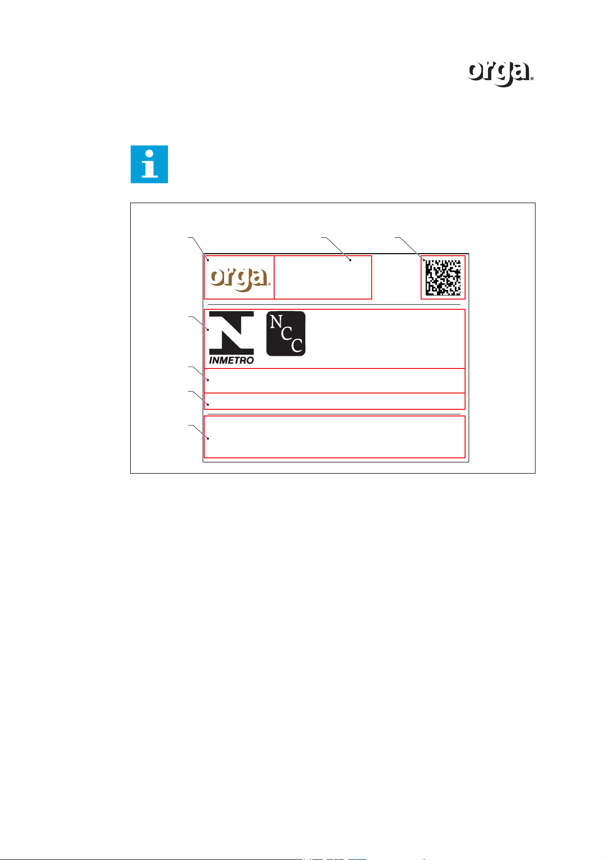
5.4.2 Labels
Note
This label is an example. The actual label may vary.
A Company logo
B Adress information
C Other logo’s such as QR code
D INMETRO logo
E Certification information
F Additional information
G Warning sign
52 Version 2.1
Page 53
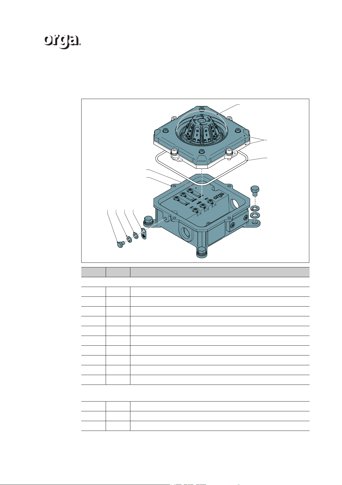
A DELIVERY AND SPARE PARTS
A.1 Delivery information L85EX
A
D
E
FGHI
B
C
/i
Amount Description
L85EX base
D 1 Housing
L 1 Control unit
B 1 Cover assembly
E4Bolt
F 4 Spring lock washer
G4 Washer
H 1 Earth cable mounting screw
I 1 Spring lock washer
J1Washer
K 1 Earthing tag
L85EX cover assembly
Including grease. Always lubricate after opening the lamp.
A1Dome
C 1 Sealing ring + grease
4 Bolt, ring, spring washer (attached to cover assembly)
Version 2.1 53
Page 54
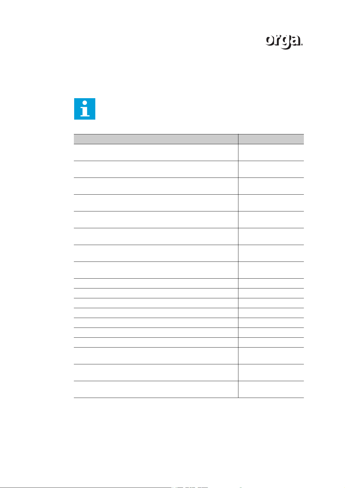
A.2 Spare parts
Depending on the platform and the local regulations, order the relevant parts. All parts that
are available are listed below.
Note
Depending on the platform and the local regulations, order the relevant parts.
All parts that are available are listed below.
/i
Name Part number
Control unit for L85EX-R-AC-50/200: LPS8511-R0900
Includes O-ring and adhesive. Always apply before closing the lamp.
071819
Control unit for L85EX-R-AC-32 (LPS8511-R0910)
Includes O-ring and adhesive. Always apply before closing the lamp.
Control unit for L85EX-G/B-AC (LPS8511-R0920)
Includes O-ring and adhesive. Always apply before closing the lamp.
Control unit for L85EX-R-AC-10 & L85EX-Y-AC (LPS8511-R0930)
Includes O-ring and adhesive. Always apply before closing the lamp.
Control unit for L85EX-R-DC50/200 (LPS2411-R1200)
Includes O-ring and adhesive. Always apply before closing the lamp.
Control unit for L85EX-R-DC-32 (LPS2411-R1210)
Includes O-ring and adhesive. Always apply before closing the lamp.
Control unit for L85EX-G-DC & L85EX-B-DC (LPS2411-R1220)
Includes O-ring and adhesive. Always apply before closing the lamp.
Control unit for L85EX-R-DC-10 & L85EX-Y-DC (LPS2411-R1230)
Includes O-ring and adhesive. Always apply before closing the lamp.
Cover assembly for L85EX-G-AC (green LEDs) 071823
Cover assembly for L85EX-R-AC-10/32 (red LEDs) 071824
Cover assembly for L85EX-R-AC-50 (red LEDs) 071825
Cover assembly for L85EX-R-AC-200 (red LEDs) 071826
Cover assembly for L85EX-B-AC (blue LEDs) 071827
Cover assembly for L85EX-Y-AC (yellow LEDs) 071828
O-ring adhesive (Soudal Silirub 2 (310ml)) 074522
071820
071821
071822
074998
075000
075002
075004
Dome set
Includes dome, clamping ring (+4 bolt sets), sealing ring
O-ring set
Includes adhesive.
Earth bolt set
Includes earth mounting bolt, spring lock washer, washer, earthing tag
54 Version 2.1
071830
074520
017129
Page 55
BATEX CERTIFICATE
Unit 6, Hawarden Industrial Park,
Hawarden
, CH5 3US, United Kingdom
Tel: +44 (0) 1244 670 900
Fax: +44 (0) 1244 539 301
Email:
Web:
www.csagroupuk.org
Project Number 70044202 C Ellaby
Deputy Certification Manager
This certificate and its schedules may only be
reproduced in its entirety and without change.
Page 1 of 4
Form 9400 Issue 2
1
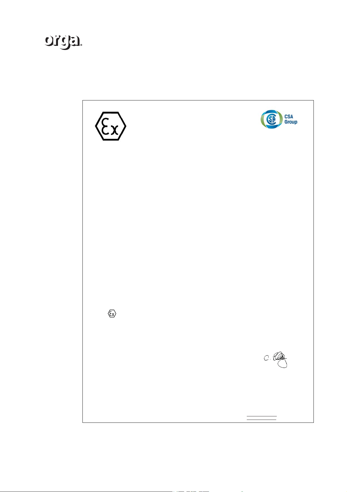
EC TYPE-EXAMINATION CERTIFICATE
2 Equipment intended for use in Potentially Explosive Atmospheres Directive 94/9/EC
3 Certificate Number: Sira 12ATEX3066 Issue: 5
4Equipment: L85EX-x-xx-xx Range of LED Lighting Fixtures
5 Applicant: Orga B.V.
6 Address: Strickledeweg 13
3125 AT Schiedam
The Netherlands
7 This equipment and any acceptable variation thereto is specified in the schedule to this certificate and
the documents therein referred to.
8 Sira Certification Service, notified body number 0518 in accordance with Article 9 of Directive 94/9/EC
of 23 March 1994, certifies that this equipment has been found to comply with the Essential Health and
Safety Requirements relating to the design and construction of equipment intended for use in
potentially explosive atmospheres given in Annex II to the Directive.
The examination and test results are recorded in the confidential reports listed in Section 14.2.
9 Compliance with the Essential Health and Safety Requirements, with the exception of those listed in
the schedule to this certificate, has been assured by compliance with the following documents:
EN 60079-0:2012 EN 60079-7:2007 EN 60079-18:2015
The above list of documents may detail standards that do not appear on the UKAS Scope of Accreditation, but have been added
through Sira’s flexible scope of accreditation, which is available on request.
10 If the sign ‘X’ is placed after the certificate number, it indicates that the equipment is subject to special
conditions for safe use specified in the schedule to this certificate.
11 This EC type-examination certificate relates only to the design and construction of the specified
equipment. If applicable, further requirements of this Directive apply to the manufacture and supply of
this equipment.
12 The marking of the equipment shall include the following:
II 2G
Ex e mb IIC T4 Gb
(Ta =-40°C to +55°C or +60°C) - See Variations 4 and 5
B.1 EC-Type Examination certificate L85EX
Version 2.1 55
S ira Cert ificat ion Serv ice
Page 56
Unit 6, Hawarden Industrial Park,
Hawarden
, CH5 3US, United Kingdom
Tel: +44 (0) 1244 670 900
Fax: +44 (0) 1244 539 301
Email:
Web:
www.csagroupuk.org
SCHEDULE
EC TYPE-EXAMINATION CERTIFICATE
Sira 12ATEX3066
Issue 5
This certificate and its schedules may only be
reproduced in its entirety and without change.
Page 2 of 4
Form 9400 Issue2
13 DESCRIPTION OF EQUIPMENT
The Lighting Fixture range L85EX-x-xx-xx is designed as a range of warning and signal beacons. The
construction of the L85EX consists of a rectangular stainless steel body with non-metallic dome lens and
clamping ring. Four mounting feet are formed as part of the base for floor mounting. The L85EX
consists of an encapsulated power supply mounted within the metallic body with increased safety
terminals and an increased safety LED light engine. The cover of the main body is secured with four
screws and the clamping ring is retained with a further four screws. External connection to the device is
through two off cable entries located in the base which may be M16, M20, M25, ½” NPT or 3/8” NPT.
Electrical data - Power supply to L85EX: 100-254 V a.c. 50-60Hz
Temperature ranges - The L85EX have the following temperature ranges:
Arrangement Temp. range Arrangement Temp. range
Red LEDs up to 260 mA -50°C to +45°C Blue LEDs up to 140 mA -50°C to +45°C
Red LEDs up to 385 mA -50°C to +40°C White LEDs up to 140 mA -50°C to +45°C
Green LEDs up to 140 mA -50°C to +45°C Yellow LEDs up to 260 mA -50°C to +45°C
200 cd setup -50°C to +40°C
Variation 1 - This variation introduced the following changes:
i. The addition of a recessed cover for the L85EX-x-xx-xx range of LED lighting fixtures that
introduces component certified swivel adaptors and a new Condition of Certification.
ii. As a result of the assessment, the Special Condition for Safe Use was no longer required and
therefore the ‘X’ suffix was removed from the certificate number.
Variation 2 - This variation introduced the following changes:
i. The introduction of an optional DC input power supply with an input supply voltage range of
20-30 Vd.c. The Conditions of Certification were amended accordingly.
Variation 3 - This variation introduced the following changes:
i. To permit the introduction of the Type 200cd model. This is identical in construction to existing
models with the exception that this model utilises an alternative LED light engine and includes Lens
covers for the LEDs.
ii. The component certified swivel adaptor range introduced previously for the recessed version was
extended to all L85EX-x-xx-xx Range of LED Lighting Fixtures, a Condition of Certification was
revised accordingly.
Variation 4 - This variation introduced the following changes:
i. The Lighting Fixtures were allowed to be used with an alternative type of LED; the ambient
temperature ranges associated with this new arrangement are detailed below as they differ from
that originally specified which are unaltered.
Arrangement Temp. range Arrangement Temp. range
Red LEDs up to 260 mA -40°C to +60°C Blue LEDs up to 140 mA -40°C to +60°C
Red LEDs up to 385 mA -40°C to +55°C White LEDs up to 140 mA -40°C to +60°C
Green LEDs up to 140 mA -40°C to +60°C Yellow LEDs up to 260 mA -40°C to +60°C
200 cd setup -40°C to +55°C
The Marking Section was amended accordingly.
56 Version 2.1
S ira Cert ificat ion Serv ice
Page 57
Unit 6, Hawarden Industrial Park,
Hawarden
, CH5 3US, United Kingdom
Tel: +44 (0) 1244 670 900
Fax: +44 (0) 1244 539 301
Email:
Web:
www.csagroupuk.org
SCHEDULE
EC TYPE-EXAMINATION CERTIFICATE
Sira 12ATEX3066
Issue 5
This certificate and its schedules may only be
reproduced in its entirety and without change.
Page 3 of 4
Form 9400 Issue2
ii. Issue 3 of the certificate introduced the Type 200cd setup, which is now included in original
temperature range table.
iii. It was recognised that these devices can have up to two M16, M20, M25, 1/2” NPT or 3/8” NPT
cable entries located in the underside of the Lighting Fixture base.
iv. The introduction of alternative methods of securing the dome lens in the Lighting Fixture for the
original and recessed versions was recognised.
v. Following appropriate re-assessment, the previous standard EN 60079-0:2009 was replaced by
EN 60079-0:2012.
Variation 5 - This variation introduced the following changes:
i. Typographical errors on previously certified drawings were corrected by changing the specification
of the original sealing ring material.
ii. The use of an alternative, silicone rubber sealing rings was recognised.
iii. The manufacturer requested that -50°C, +40°C and +45°C ambient temperature options should be
removed from the marking section as they are no longer required, however, they have been left in
the Description of Equipment to maintain the history of the product.
iv. Following appropriate assessment to demonstrate compliance with the latest technical knowledge, EN
60079-18:2009 was replaced by EN 60079-18:2015.
14 DESCRIPTIVE DOCUMENTS
14.1 Drawings
Refer to Certificate Annexe.
14.2 Associated Sira Reports and Certificate History
Issue Date Report no. Comment
0 13 June 2012 R25524A/00 The release of the prime certificate.
1 07 May 2013 R29038A/00 The introduction of Variation 1.
2 15 May 2013 R29079A/00 The introduction of Variation 2.
3 21 May 2013 R29185A/00 The introduction of Variation 3.
4 06 February 2015 R70005155A The introduction of Variation 4.
5 16 February 2016 R70044202A The introduction of Variation 5.
15 SPECIAL CONDITIONS FOR SAFE USE (denoted by X after the certificate number)
None.
16 ESSENTIAL HEALTH AND SAFETY REQUIREMENTS OF ANNEX II (EHSRs)
The relevant EHSRs that are not addressed by the standards listed in this certificate have been
identified and individually assessed in the reports listed in Section 14.2.
17 CONDITIONS OF CERTIFICATION
17.1 The use of this certificate is subject to the Regulations Applicable to Holders of Sira Certificates.
17.2 Holders of EC type-examination certificates are required to comply with the production control
requirements defined in Article 8 of directive 94/9/EC.
17.3 A visual inspection of the encapsulation is to be completed; no damage such as cracks, exposure of
encapsulated parts, flaking, inadmissible shrinkage, swelling, decomposition failure of adhesion or
softening shall be evident.
Version 2.1 57
S ira Cert ificat ion Serv ice
Page 58
Unit 6, Hawarden Industrial Park,
Hawarden
, CH5 3US, United Kingdom
Tel: +44 (0) 1244 670 900
Fax: +44 (0) 1244 539 301
Email:
Web:
www.csagroupuk.org
SCHEDULE
EC TYPE-EXAMINATION CERTIFICATE
Sira 12ATEX3066
Issue 5
This certificate and its schedules may only be
reproduced in its entirety and without change.
Page 4 of 4
Form 9400 Issue2
17.4 The dielectric strength test according to EN 60079-18:2009 clause 8.2.4 shall be applied to the AC
power supply for at least 1 second, the test voltage shall be at least 1620 V d.c.. Alternatively, 1.2 x
test voltage may be applied and maintained for at least 100ms.
17.5 ThedielectricstrengthtestaccordingtoEN60079-18:2009clause8.2.4shallbeappliedtotheDC
power supply for at least 1 second, the test voltage shall be at least 500 V d.c.. Alternatively, 1.2 x test
voltage may be applied and maintained for at least 100ms.
17.6 The dielectric strength test according to EN 60079-7:2007 clause 6.1 shall be applied to the light
engine for at least 60 seconds, the test voltage shall be at least 500 V d.c.. Alternatively, 1.2 x test
voltage may be applied and maintained for at least 100 ms.
17.7 The L85EX-x-xx-xx Range of LED Lighting Fixtures incorporates previously certified devices, it is
therefore the responsibility of the manufacturer to continually monitor the status of the certification
associated with these devices, and the manufacturer shall inform Sira of any modifications of the
devices that may impinge upon the explosion safety design of their products.
S ira Cert ificat ion Serv ice
58 Version 2.1
Page 59
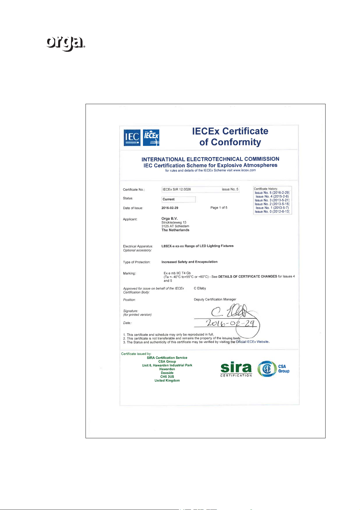
C IECEx CERTIFICATE
C.1 IECEx Certificate of Conformity L85EX
Version 2.1 59
Page 60
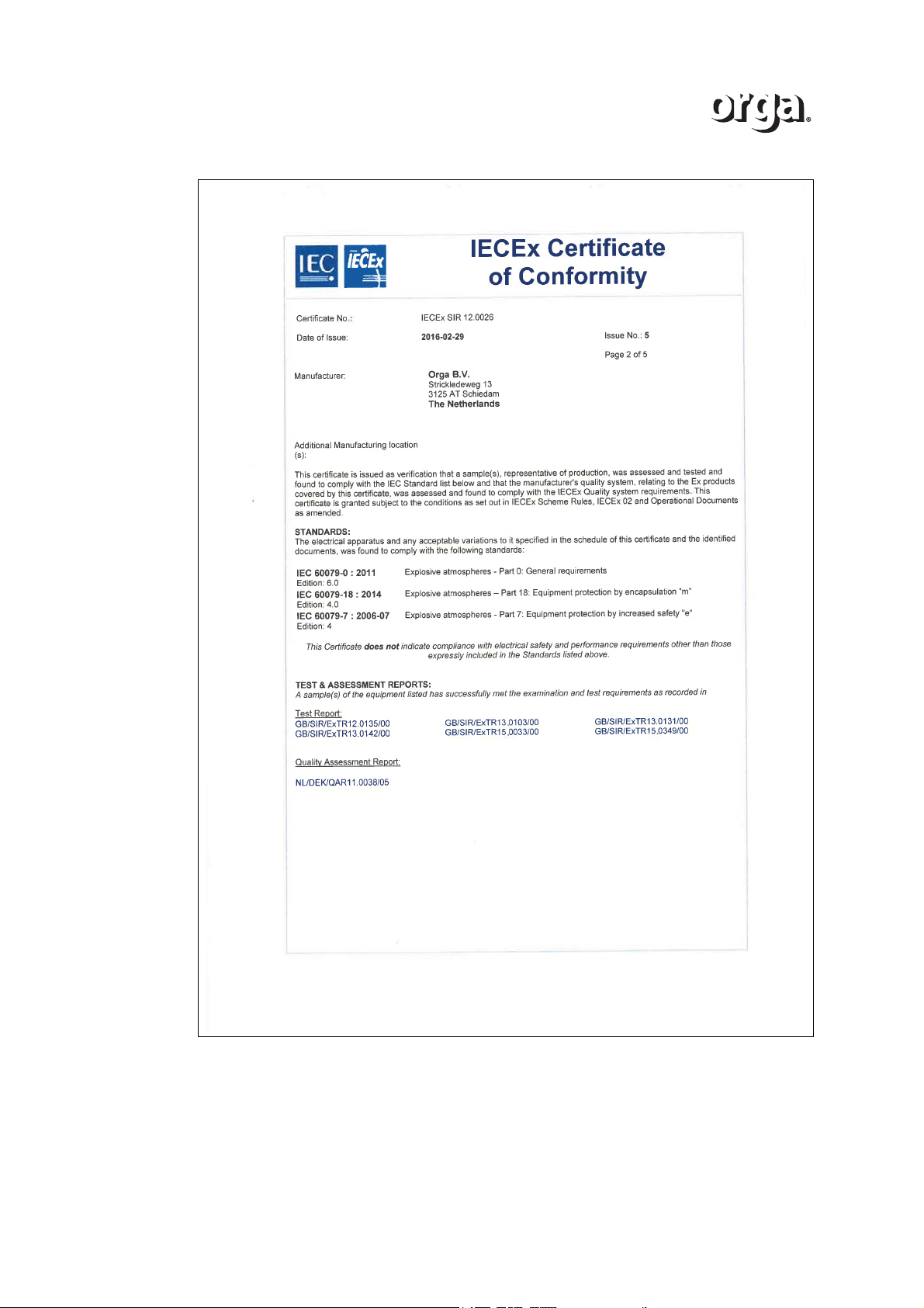
60 Version 2.1
Page 61
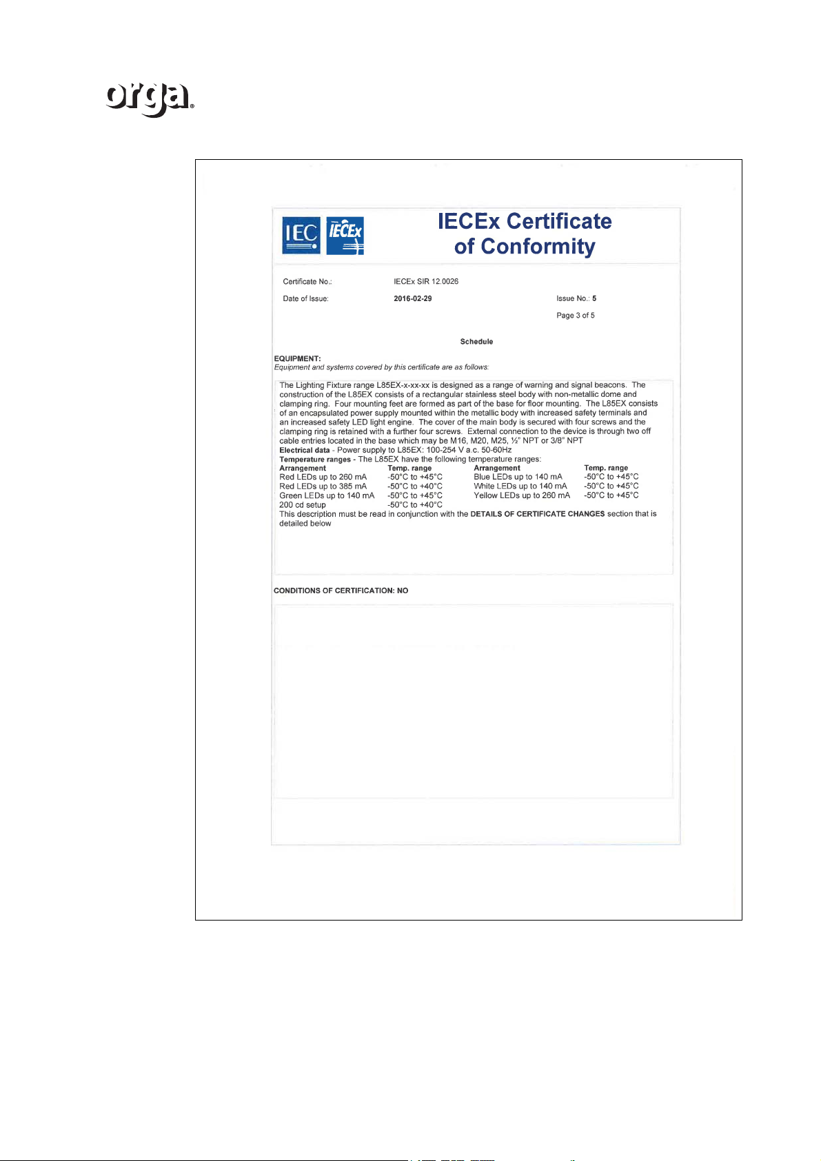
Version 2.1 61
Page 62
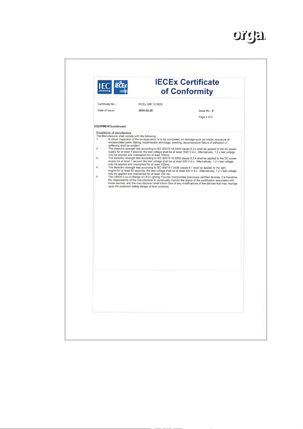
62 Version 2.1
Page 63
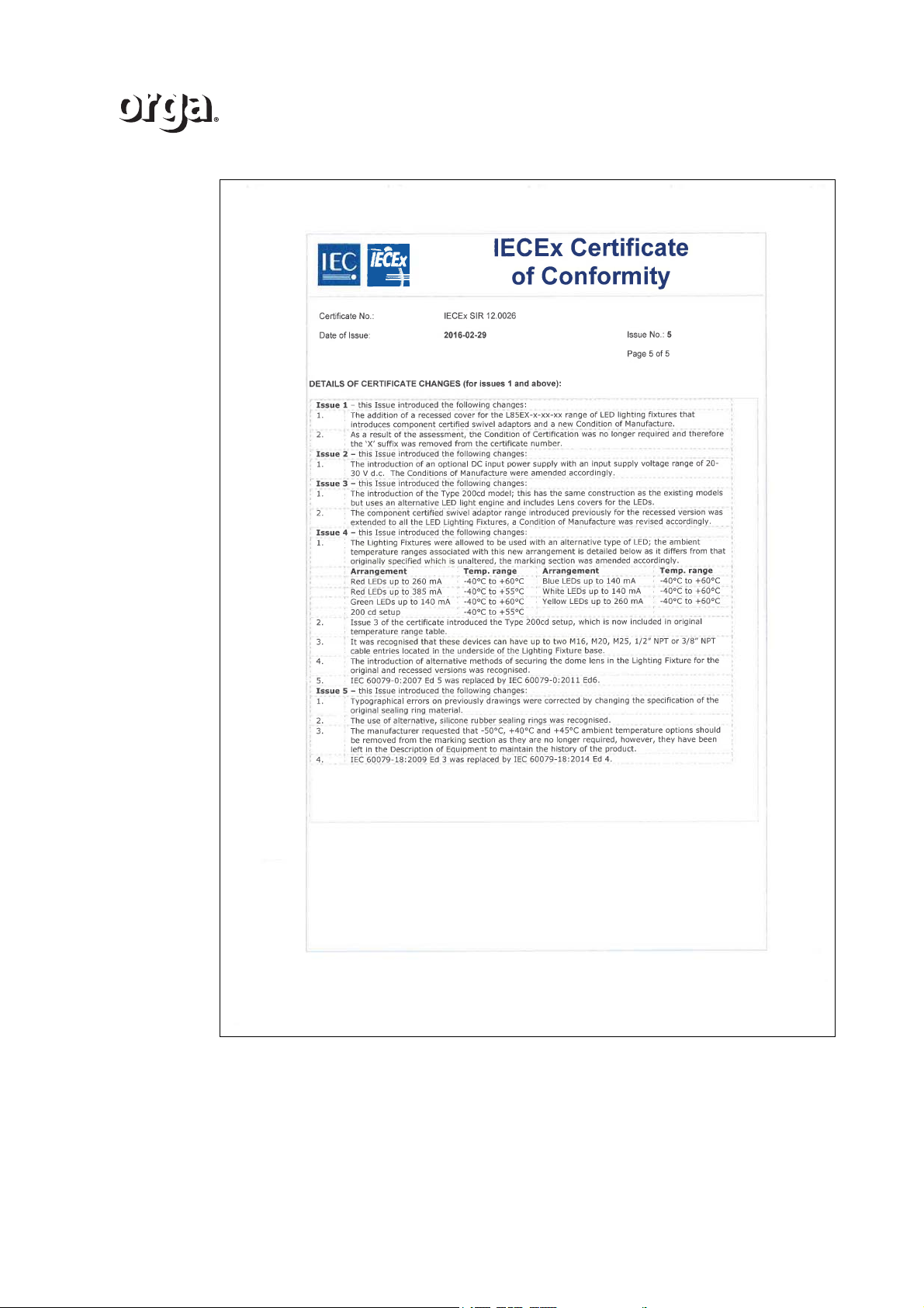
Version 2.1 63
Page 64

64 Version 2.1
Page 65
D EC - Declaration of Conformity
EU-Declaration of Conformity
Wij, Orga BV, verklaren geheel onder eigen verantwoordelijkheid dat het product
We, Orga BV, declare under sole responsibility that the product
LED LIGHTING FIXTURES type L85EX-x-xx
waarop deze verklaring betrekking heeft, in overeenstemming is met de volgende
bepaling(en):
to which this declaration relates is in conformity with the following provisions of directive(s):
EMC-RICHTLIJN: 2014/30/EU
EMC-DIRECTIVE: 2004/108/EC
ATEX RICHTLIJN: 2014/34/EU
Het product is gecertificeerd door: Met certificaat nummer:
The equipment is certified by: With certificate number:
Sira Certification Service SIRA 12ATEX3066
Rake Lane
Eccleston, Chester CH4 9JN
England
Uitvoering:
Execution:
ll 2 G Ex e mb llC T4 Gb
DEKRA Certification BV 0344
In overeenstemming met de volgende (geharmoniseerde) norm(en):
In accordance with the following (harmonized) standards:
EN 60079-0 : 2012 NEN-EN-IEC 61000-6-2 : 2005
EN 60079-7 : 2007 NEN-EN-IEC 61000-6-4 : 2007
EN 60079-18 : 2009
P. Voorwald-Snijder
Schiedam, 28/07/2016 QHSE Manager
ATEX L
85
_R05
D.1 EC - Declaration of Conformity L85EX
Version 2.1 65
Page 66

66 Version 2.1
Page 67
E Ex CERTIFICATE
Certificado de Conformidade Ex
Ex Certificate of Conformity
Modelo com Avaliação do Sistema de Gestão da Qualidade do Processo de
Produção e Ensaios no Produto
Model with Assessme nt of Qu ality Mana gement Syst em of Production Pr ocess and Test on Product
Certificad o Nº:
Certificate Nº:
NCC 12.1223
Emissão/is sue nº.: 3
Data de emissão:
Issued date:
31-03-2016
Página 1 de 5
Page 1 of 5
FNCC_205 Rev. 14
Data de validade:
Validity date:
31-03-2019
Histórico do certific ado:
Certificate h istory:
Solicitante:
Applicant:
Orga B.V.
Strickledeweg 13, Schied am, 3125 AT
Holan da
Produto:
Product:
Lâmpada de sinalização LED L85EX-x-xx-xx
Tipo principal de proteção:
Main type of prot ection:
e, m
Marcação:
Marking:
Ex e mb IIC T4 Gb
T
amb
– Ver tabela 1
Aprovado par a emissão em c onformidade com o regulamento e normas
aplicáveis
Organismo de Certificação:
Approved f or issue in confor mity with ru le and app licab le standards
Certificatio n body:
Posição:
Position:
Wilson Bonato
Gerente T écnico
Technical M anager
Certificado emitido conforme requisitos da avaliação da conformidade de equipamentos elétricos para atmosferas
explosivas, anexo à Portaria Inmetro nº. 179 de 18 de maio de 2010
Certificate issued i n according to Br azilian requirem ents attached to I NMETRO ’s Rule nº. 179 i ssued on May 18th, 2010
1. Este certificado somente pode ser reproduzido com todas as folhas.
This cert ificate may only be r eproduced in full.
2. Es te certific ado não é transf erível e é de propriedade do organismo emiss or.
This certific ate is not transf erable and re mains the prop erty of the iss uing body.
3. A situação e autenticidad e deste certif icado podem ser verificadas no website oficial do Inmetro.
The Status and auth enticity of this cert ificate may be verif ied by v isiting the w ebsite of the Inmetr o.
4. Este certificado de conformidade foi emitido por um organismo de certificação acreditado pela CGCRE - Coordenação Geral de Acreditação.
This cert ificate of co nformity was iss ued by a c ertificat ion body acc redited by C GCRE .
Certificad o emitido por:
Cert if icat e iss ued by:
NCC Certificações do Brasi l Ltda.
Acreditação CGRE n°0034 (16/10/2003)
www.ncc.com.br
Emissão No. 3 (31-03-2016)
Emissão No. 2 (18-12-2013)
Emissão No. 1 (10-12-2013)
Emissão No. 0 (27-12-2012)
E.1 Ex Certificate of Conformity L85EX (optional)
Version 2.1 67
Page 68
Certificado de Conformidade Ex
Ex Certificate of Conformity
Modelo com Avaliação do Sistema de Gestão da Qualidade do Processo de
Produção e Ensaios no Produto
Model with Assessme nt of Qu ality Mana gement Syst em of Production Pr ocess and Test on Product
Certificad o Nº:
Certificate Nº:
NCC 12.1223
Emissão/is sue nº.: 3
Data de emissão:
Issued date:
31-03-2016
Página 2 de 5
Page 2 of 5
Fabricante:
Manufact urer:
Orga B.V.
Strickledeweg 13, Schied am, 3125 AT
Holan da
Unidades f abris adici onais:
Additional manufacturing
locations:
N/A
Este certific ado é emitido como uma verific ação que amostras, representativas d a linha de produç ão, foram avaliadas e ensaiadas e atenderam às
normas relacionadas abaixo, e que o sist ema de gestão da qual idade do f abricante, relativo aos produtos Ex cob ertos por este certificado, foi
avaliado e aten deu aos requisitos do Regulamento Inmetro. Este certificado é concedido sujeito às condições previs tas no Regulamento Inmetro.
This certif icate is iss ued as verif ication that samples , represent ative of prod uction, wer e assessed and teste d and found t o comply with the
standards listed be low and that the manufactur er’s quality mana gement sy stem, rela ting to th e Ex produc ts cover ed by this certifica te, was as sessed
and found t o comply w ith the Inmetro R egulation . This cert ificate is granted subject to the cond itions as s et out in Inmetro Ru les.
NORMAS:
STANDARDS:
O produto e quaisquer variações aceitáv eis para ele especificados na relação deste certificado e docum entos mencionados atendem às seguintes
normas:
The produc t and any acceptab le variat ions to it s pecified in the sch edule of t his cert ificate and t he ident ified docu ments, was found to comply with
following standards:
ABNT NBR IEC 60079-0:2013
Atmosferas Explosivas – Parte 0: E quipamentos – R equisitos gerais.
ABNT NBR IEC 60079-7:2008
Versão corrigida em 2010
Atmosferas Explosivas – Parte 7: Prot eção de equipamentos por segur ança aumentada “e ”.
ABNT NBR IEC 60079-18:2010
Atmosferas Explosivas – Parte 18: Pr oteção de equipament os por enc apsulamento “m”.
Este certificado não indica c onformidade com ou tros requis itos de seguranç a e desemp enho elétr ico além daqu eles expressamente incluídos nas
normas relacionadas acima.
This ce rtif icate does not indicate c ompliance w ith electrical safe ty and per formanc e require ments oth er than th ose express ly inc luded in the
standards above listed.
RELATÓRIOS DE ENSAIO E AVALIAÇÃO:
TEST AND ASSESSMENT REPOR TS:
Amostras do(os) produto(os) relacionado(os) p assou (passaram) com suc esso nas avaliações e ensaios registrados em:
Samples of the prod uct(s) lis ted have s uccessfully met th e examinat ion and tes t require ments as r ecorded in :
Registro de avalia ção da conform idade técnica (apresenta a relação dos documentos utili zados para análise e as conclusões para a
recomendação da certificação):
Technical conformity a ssessment register ( presents the relat ion of the documents used for analysis a nd conclus ions for the rec ommendat ion of
cer tifica tion):
BPM: 253785
Proc esso: 31291 /15 .2
Relatório(s) de ensaio:
Test report(s):
GB/SIR/ExT R13.0142/ 00 (SIRA - 17/05/2 013)
GB/SIR/ExTR13.0131/00 (SIRA - 07/05/2013)
GB/SIR/ExTR13.0103/00 (SIRA - 19/04/2013)
GB/SIR/ExTR12.0135/00 (SIRA - 29/05/2012)
GB/SIR/ExTR15.0033/00 (SIRA – 04/02/ 2015)
GB/SIR/ExTR15.0349/00 (SIRA - 24/12/2015)
Relatório de auditoria / Relatório d e Avaliação da Qualidade:
Audit report / Qua lity Assessment Rep ort:
NCC: 13 e 14/04/2015
FNCC_205 Rev. 14
68 Version 2.1
Page 69
Certificado de Conformidade Ex
Ex Certificate of Conformity
Modelo com Avaliação do Sistema de Gestão da Qualidade do Processo de
Produção e Ensaios no Produto
Model with Assessme nt of Qu ality Mana gement Syst em of Production Pr ocess and Test on Product
Certificad o Nº:
Certificate Nº:
NCC 12.1223
Emissão/is sue nº.: 3
Data de emissão:
Issued date:
31-03-2016
Página 3 de 5
Page 3 of 5
FNCC_205 Rev. 14
DESCRIÇÃO:
DESCRIPTION:
Prod utos e s ist emas abr ang idos po r est e certific ado são c omo seg ue:
Products a nd systems covere d by this c ertificate are as fo llows:
O equipamento é projetado como um sinalizador de ad vertência. Ele é constituíd o de um corpo retangular de aço inoxidá vel com uma cúpula não
metálica e um an el de fixação. Quatro pés de mon tagem são utilizados como parte da base para montagem no chão. Tamb ém é const ituído de
uma fonte de alimentação e circuit os de diodos zener enc apsulados montados dentro do corpo metálic o com terminais, PCI LED, fiação e
mecanismo de iluminação LED de seguranç a aumentada.
A tampa do corpo princ ipal é fixada através de quatr o parafusos e o an el de fixação é mantido através de mais quatro parafuso s. Conexão exter na
ao dispositi vo é realizad a através de duas entradas de cabos localizadas na base, as quais podem ser M16, M20, M25, ½” NPT ou 3/8” NPT.
Características técnicas: Un = 100-254 VCA, f = 50-60 Hz
Tabela / Table 1
Configuração
Temperatur a ambiente
LEDs vermelh os até 260 mA
-40 °C até +60 °C
LEDs vermelh os até 385 mA
-40 °C até +55 °C
LEDs verdes até 140 mA
-40 °C até +60 °C
200 cd setu p
-40 °C até +55 °C
LEDs azuis at é 140 mA
-40 °C até +60 °C
LEDs brancos até 140 mA
-40 °C até +60 °C
LEDs amarel os até 260 mA
-40 °C até +60 °C
CONDIÇÕES DE CERTIFICAÇÃO:
CONDITIONS OF CERTIFICATION:
Este certific ado é válido apenas para o produto de modelo idêntico ao produt o efetivamente ensaiado. Quaisquer modificações no projeto, bem
como a utiliz ação de compon entes e/ou materiais dif erentes daquele s definidos pela documentação descritiva do produto, sem a prévia autorização
da NCC, invalidarão este certificado.
This cert ificate is va lid only for the mo del of pr oduct id entical to effectiv ely tested. Any chang es in the project, a nd the use of co mponen ts and / or
materials d ifferent fr om those d efined by the d escript ive document ation of t he pro duct, with out the prior p ermiss ion of the NCC, will invalid ate this
cer tific ate.
O usuário tem respons abilidade de assegurar que o produt o será inst alado/utili zado em atendimento às instruções do fabricante e às n orm as
pert inent es em instal ações el étr icas em atmosf eras exp losivas .
The user is respons ible for e nsuring t hat the pr oduct must be ins talled / used ac cording t he manufac turer's instructio ns and the relev ant standar ds in
electrical installations in explosive atmospheres.
As atividades de instalação, inspeção, manutenç ão, reparo, revisão e recuperação dos equipament os são de respons abilidade dos usuários e
devem ser executadas de acord o com os requisit os das normas técn icas vigent es e com recomendações do f abricante.
The installa tion activities , inspect ion, mainten ance, repa ir, overhaul and rec overy of equipme nt are the respo nsibility of us ers and must be
implemente d in accor dance wit h the req uirements of current technical standards and ma nufacture r's recomm endations .
Por se tratar de um processo de certificação cujo solicitante não é estabelecido legalmente no Brasil, o mesmo possui um representante legal
estabelecido neste país, o qual se responsabiliza em atender aos itens 7 e 10.1 da Portaria Inmetro nº 179 de 18 de maio de 2010.
This certif ication proc ess is related t o applicant who is not lega lly establis hed in Braz il, but has a leg al represent ative i n this country, who is
responsible to meet to items 7 and 10.1 of Inmetro Regulation No. 179 (May 18
th
, 2010).
Represent ante(s) leg al(is):
Legal repr esentativ e:
SOLAS REPRESENTACOES TECNICAS E COMERCIAIS LT DA
CNPJ: 00.147.514/0001-74
Version 2.1 69
Page 70

Certificado de Conformidade Ex
Ex Certificate of Conformity
Modelo com Avaliação do Sistema de Gestão da Qualidade do Processo de
Produção e Ensaios no Produto
Model with Assessme nt of Qu ality Mana gement Syst em of Production Pr ocess and Test on Product
Certificad o Nº:
Certificate Nº:
NCC 12.1223
Emissão/is sue nº.: 3
Data de emissão:
Issued date:
31-03-2016
Página 4 de 5
Page 4 of 5
Condições de fabricação:
Conditions of manufactur ing:
O equipamento listado deverá passar pelos seguintes ensaios de rotina:
Ens aio de rigidez dielétrica sobre o mecanis mo de iluminação, de acordo c om item 6.1 da ABNT NBR IEC 6 0079 -7;
Ens aio de rigidez dielétrica sobre a fonte de aliment ação CC, d e acordo c om item 8.2.4 d a ABNT NBR IEC 60079-18;
Ensaio de rigidez diel étrica sobre a f onte de aliment ação CA, de acor do com item 8.2. 4 da ABNT NBR IEC 60079 -18;
Dever á evidenciar por inspeção visual que o pr eenchiment o do encapsulamento foi realizado sem danos, ta is como rachadur as,
exposição de peças encapsuladas, d escamação, r etração inadmissível, inchaço, insuficiênci a de adesão ou am oleciment o, de acor do
com o item 9.1 da ABNT NBR IEC 60079-18.
Marcação de advertência:
Warning marking:
ATENÇÃO – NÃO ABRA QUANDO ENERGIZADO
ATENÇÃO – RISCO POT ENCIAL DE CARGA ELETROSTÁTICA – VER INSTRUÇÕES
DETALHES DE EMISSÕES DO CERT IFICADO (para emi ssões 0 e posteriores):
DETAILS OF CERTIFICATE ISSUES (for issues 0 and above):
Emissão 0:
Issue 0:
Emissão inicial.
Emissão 1:
Issue 1:
Alterações de modelos, exclusão de condições específicas de utilização.
Emissão 2:
Issue 2:
Correção na descrição dos ensaios de rotina.
Emissão 3:
Issue 3:
Revisão de documentação descritiva e faixas de temperatura ambiente.
DOCUMENTAÇÃO CONTROLADA, DESCRITIVA DO PRODUTO (CONFIDENCIAL):
DESCRIPTIVE CONTROLLED DOCUMENTS O F THE PRODUCT (CONFIDE NTIAL):
Tabela / Table 2
Identificação
Identification
Revisão
Issue
Identificação
Identification
Revisão
Issue
Identificação
Identification
Revisão
Issue
SW-000445 4
16/04/2013 LPS2411-EL02R0
0 LED3501-E P01
0
SW-000446 0
16/04/2013 LPS2411-EL03R0
0 L85EX-200CD-IW -01
0
SW-000446 1
16/04/2013 LPS2411-EL04R0
0 LPS2411-EL01R0
0
SW-000446 2
16/04/2013 LPS2411-EL05R0
0 L85EX-IW -01r0
0
LED3501-E L01
0 LPS2411-ES01R0
0 LED8508-E P01R0
0
LED3501-E L02
0 LPS2411-EP01R1
1 LPS8511-ES01R2
R2
FNCC_205 Rev. 14
70 Version 2.1
Page 71
Certificado de Conformidade Ex
Ex Certificate of Conformity
Modelo com Avaliação do Sistema de Gestão da Qualidade do Processo de
Produção e Ensaios no Produto
Model with Assessme nt of Qu ality Mana gement Syst em of Production Pr ocess and Test on Product
Certificad o Nº:
Certificate Nº:
NCC 12.1223
Emissão/is sue nº.: 3
Data de emissão:
Issued date:
31-03-2016
Página 5 de 5
Page 5 of 5
FNCC_205 Rev. 14
Tabela (cont.) / Table (cont.) 2
Identificação
Identification
Revisão
Issue
Identificação
Identification
Revisão
Issue
Identificação
Identification
Revisão
Issue
5144-APPR-AA01
2 5144-APPR-AA51
2 LED3508-E L01
1
LED3501-E L03
0 5144-APPR-AA61
3 5144-APPR-AA61
2
5144-APPR-B31
1 SW- 0003863
A03 SW-000389 7
A00
5144-APPR-B01
1 SW- 0003898
A02 015335
A03
LPS8511-EL01
1 SW- 0003874
A01 Instruções sobre o L85EX
27/07/2015
LPS8511-EL04
1 LED3508EX
07/02/2012 SW-000243 3
A09
LPS8511-EL02
1 LPS8511-EP01R2
2 5144-APPR-AA04
1
LED3508-E L03
1 LPS8511-EL05
1 5144-APPR-AA03
1
LED3508-E L02
1 LPS8511-EL03
1 APPR-AA71
1
LED3501-E L04
0 5144-APPR-B21
1 SW-000387 3
A00
5144-APPR-AA02
1 SW- 0008672
A02 SW- 0008596
A00
SW-0008673
A00 SW- 0008666
A02 SW- 0008607
A02
SW-0008591
A01 SW- 0008604
A03 SW- 0009068
A01
Version 2.1 71
Page 72

For information about maintenance or repair that is not in this manual, please contact the Orga service
support department.
/i
ORGA BV
Strickledeweg 13
3125 AT SCHIEDAM
The Netherlands
+31 (0) 10 208 5550
[email protected]
www.orga.nl
 Loading...