

Orenco Systems SB1, SB2, SB3, SB4, SB5 Installation Manual
...
Splice Boxes
814 AIRWAY AVENUE
SUTHERLIN, OREGON
97479
TELEPHONE:
(541) 459-4449
(800) 348-9843
FACSIMILE:
(541) 459-2884
The electrical splice box provides a safe and legal space for splicing cables, typically from
pumps or float switches. It should be mounted inside the access riser, over the pump or filter
unit, where the components being spliced are within sight of the installer. For explosion proof
(Class 1, Div. 1) splice boxes, please see document EIN-SB-SBX-1.
The splice box is provided with heat shrink/ butt connectors and waterproof wire nut(s)
necessary to splice the appropriate floats and pumps.
Installation, Operation and Maintenance
Model SB__
2. Push the appropriate pump and level
control wires through the watertight
cord grips into the electrical splice box.
Leave an adequate length of electrical
cable coiled inside the riser to allow for
easy removal of the pump and float
assembly. Do not remove the colored
markers or the paper tags from the float
cables, and do not try to thread the
markers and tag through the cord grip.
Tighten the cord grips
by hand, not by
tool
, then test the tightness of the cord
grips by tugging on each cable. A cable
is secure when the cord grip is tight
enough to prevent slippage. Adequate
lengths of cable should be left within
the splice box to allow easy removal for
future disconnecting and re-splicing.
1. The splice box should be mounted inside
the access riser. The access riser is
typically supplied with a grommet for
installation of the splice box. If a grommet
is not installed, please refer to riser, lid, and
accessary instructionsdocument EIN-RLARLA-1 for grommet installation
instructions.
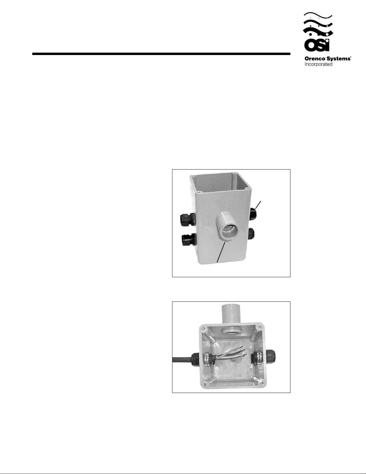
Lubricate both the outside of the conduit
coupling and the grommet. Slide the
coupling through the grommet in the
access riser wall. Make sure the box is
pushed snug against the wall, allowing for
removal of any pumping equipment.
Installation Instructions:
Cord Grip
Conduit Coupling
EIN-SB-SB-1
Rev 2.2 12/10/99
Page 1

3. Run properly sized wires from the control panel to the splice box. The wires can
be brought through a conduit, or can be direct buried using suitable direct-burial
wire. Conduit that enters the splice box must be sealed with a conduit seal or
acceptable watertight cord connection, to prevent the infiltration of water into the
splice box. The number of wires required depends on the control panel and the
number of floats and pumps used. This can be determined by consulting the
Splice Box Wiring diagram provided for the control panel and float arrangement
being used.
Installation Instructions cont.
If the floats do not carry direct pump current, the wire should be sized at 14 AWG. Refer
to Chart 1 to determine the proper size for the pump wire and any float wire required to
carry direct pump current. When calculating wire size, you need to take the length and
size of your branch circuit wires from the
service entrance panel to the pump control
panel
into account. Wire that is too small can cause an excessive voltage drop and poor
pump performance.
Chart 1. Recommended Breaker & Wire Size
Pump Motor Size Breaker size Wire Size Max Distance*
115 VAC 1/3 hp 20 amp 12 AWG 210 ft
1/2 hp 20 amp 12 AWG 160 ft
230 VAC 1/2 hp 15 amp 14 AWG 400 ft
1 hp 20 amp 12 AWG 400 ft
1 1/2 hp 20 amp 12 AWG 310 ft
* load center to motor.
Wires should be color coded or otherwise marked to aid in wiring the control panel. The
following chart lists common colors recommended for each of the wires. Colors may
refer to either the color of the wire’s insulating jacket or the color of an electrical tape
marker.
Chart 2. Recommended Field Wire Colors
Float Cables
Float Function Float Marker Wire Color
High Water Alarm Yellow Yellow
Lag Pump On (Duplex) Purple Purple
Lead Pump On (Duplex) Blue Blue
Lead Pump Off (Duplex) Red Red
On / Off Green Blue
Redundant Off / Low Level Alarm White Orange
Float Common Wire - Brown
Pump Cable(s)
Pump Wire (L1) Black
Pump Wire (Neutral, 115vpumps) White
Pump Wire (L2, 230vpumps) Red
Ground Green
EIN-SB-SB-1
Rev 2.2 12/10/99
Page 2
 Loading...