

Page 1

Panel Installation
Before Installing Panel
1. Read all instructions before proceeding with the installation. Improper installation
may void warranties.
2. Inspect your order for completeness and inspect each component for shipment
damage. If something is missing or damaged, you will need to contact your supplier
to obtain replacements.
3. Check to be sure the instructions and items supplied comply with state and local
regulations.
4. A qualified electrician must be employed to install and service the panel and ancillary
wiring. The equipment must be installed in compliance with the National Electric Code,
as well as state and local codes.
Placement of the Control Panel
5. Install the electrical control or alarm panel within view of the tank. The panel should
be attached to a post or an exterior wall. Panels that contain motor contactors make a
thumping sound, each time a pump is started or stopped. Therefore, these panels should not be
mounted to an exterior wall unless it is in a location away from living areas, such as
on a garage wall. If possible, position the panel in the shade to protect it from weather.
Extreme temperatures can cause inconsistent performance of the electrical components.
Locate the panel at a convenient height (usually about five feet above the ground) and
where it will be accessible for maintenance.
Install Floats and Pumps
6. Install the electrical splice box(es) for the floats and pump(s) before installing the
actual floats and pumping equipment. The splice box(es) are installed in the grommet(s)
provided near the top of the riser.
7. Install the floats. Thread the float and pump cords through the cord grips into the
PVC splice box, leaving adequate lengths of electrical cord coiled inside the riser to
allow easy removal of the pump and float assembly. Do not remove the colored markers
or the paper tags from the float cords, and do not try to thread the markers and tag
through the cord grip. These should be left on the float cord, outside the splice box.
Tighten the cord grips, using hand pressure or a wrench if necessary, until the cord will
no longer move in the cord grip. If the cord grips are not tight enough, the seal will not
be watertight, but overtightening may damage the cord or the cord grip, so use only as
much force as necessary. Adequate lengths of cord should be left within the splice box
to allow for easy removal for future disconnecting and re-splicing.
8. Run the wires from the control panel to the splice box. The wires can be brought
through a conduit, or can be buried using suitable direct-burial wire. Conduit that enters
the splice box must be sealed, even if the wires are direct-buried, to prevent the infiltration
of water into the splice box. Use an electrically approved sealant to plug the wires
coming in through the conduit hub. The number of wires required depends on the control
panel and the number of floats and pumps used. This can be determined by consulting
the Float Arrangement diagram appropriate for the control panel and float arrangement
being used.
EIN-CP-GEN-1
Rev 2.0 ©01/10/05
Page 1
Page 2

Wire should be sized at 14 AWG for the floats. Refer to Figure 1 to determine the
proper size for the pump wires. When calculating wire size, the length and size of the
branch circuit wires from the service entrance panel to the pump control panel must
also be taken into account. Wire that’s too small can cause an excessive voltage drop
and poor pump performance.
Wires should be color coded or otherwise marked to aid in wiring the control panel.
Drawing EIN-SB-SB-1 lists recommended colors for each of the wires. Colors may
refer to either the color of the wire’s insulation, the color of a tag, or the color of an
electrical tape marker.
9. All splices made in the splice box should use waterproof wire nuts or butt connectors
and heat shrink tubing. The splices must be waterproof! Splices that are not waterproof
may cause a malfunction of the pump controls if water should leak into the splice box.
Refer to Drawing EIN-SB-SB-1 for instructions on making waterproof splices. Refer
to the appropriate Float Arrangement diagram for instructions on how to connect the
floats together.
Connect Control Panel
10. Connect the wires coming from floats to the terminals in the control panel. Refer
to the appropriate Float Arrangement diagram for the correct terminal connections.
11. Connect the wires coming from the pump(s) to the pump terminals. Refer to the
panel wiring diagram for the correct terminal connections.
12. Connect the incoming power to the panel. Power to the panel must be appropriate
to the control panel and pump motor (i.e. 120VAC, single phase for a 120 VAC motor,
240 VAC single phase for a 240 VAC motor, etc.) Insure that the panel is properly
grounded and that the fuse or breaker and wire size, from the main power panel and to
the pump, are sized correctly. Separate circuits for the pump controls and each of the
pump motors is recommended. Note: Voltage for the controls in the panel is always
120VAC, although the pump voltage may be 120VAC or 240 VAC.
13. Use 60° minimum CU conductors only. Torque the terminal blocks to 15 LB-IN
and the ground lugs to 45 LB-IN. Torque the circuit breakers to 20 LB-IN for 14-10
AWG wire, 25 LB-IN for 8 AWG wire, and 27 LB-IN for 6-4 AWG wire.
14. When power is applied to the control panel, the wires to the pump may be energized.
Do not service the pump or any electrical wiring in the pump vault without disconnecting
the power at the circuit breaker and the fuse. The pump vault area is a hazardous area,
and may contain explosive gases. Take appropriate precautions before working in the
pump vault.
15. If you have any questions please contact Orenco Systems, Inc.
Figure 1. Recommended Breaker & Wire Size
Pump Motor Size Breaker size Wire Size Max Distance*
120 VAC 1/2 hp 20 amp 10 AWG 105 ft
240 VAC 1/2 hp 15 amp 14 AWG 161 ft
3/4 hp 20 amp 14 AWG 130 ft
1 hp 20 amp 12 AWG 172 ft
1 1/2 hp 20 amp 12 AWG 126 ft
* This is the maximum distance from this subpanel to the pump motor for the
recommended wire size. Distance is based on 3% maximum voltage drop from subpanel
to load at maximum recognized pump motor amps at 75° C.
EIN-CP-GEN-1
Rev 2.0 ©01/10/05
Page 2
Page 3
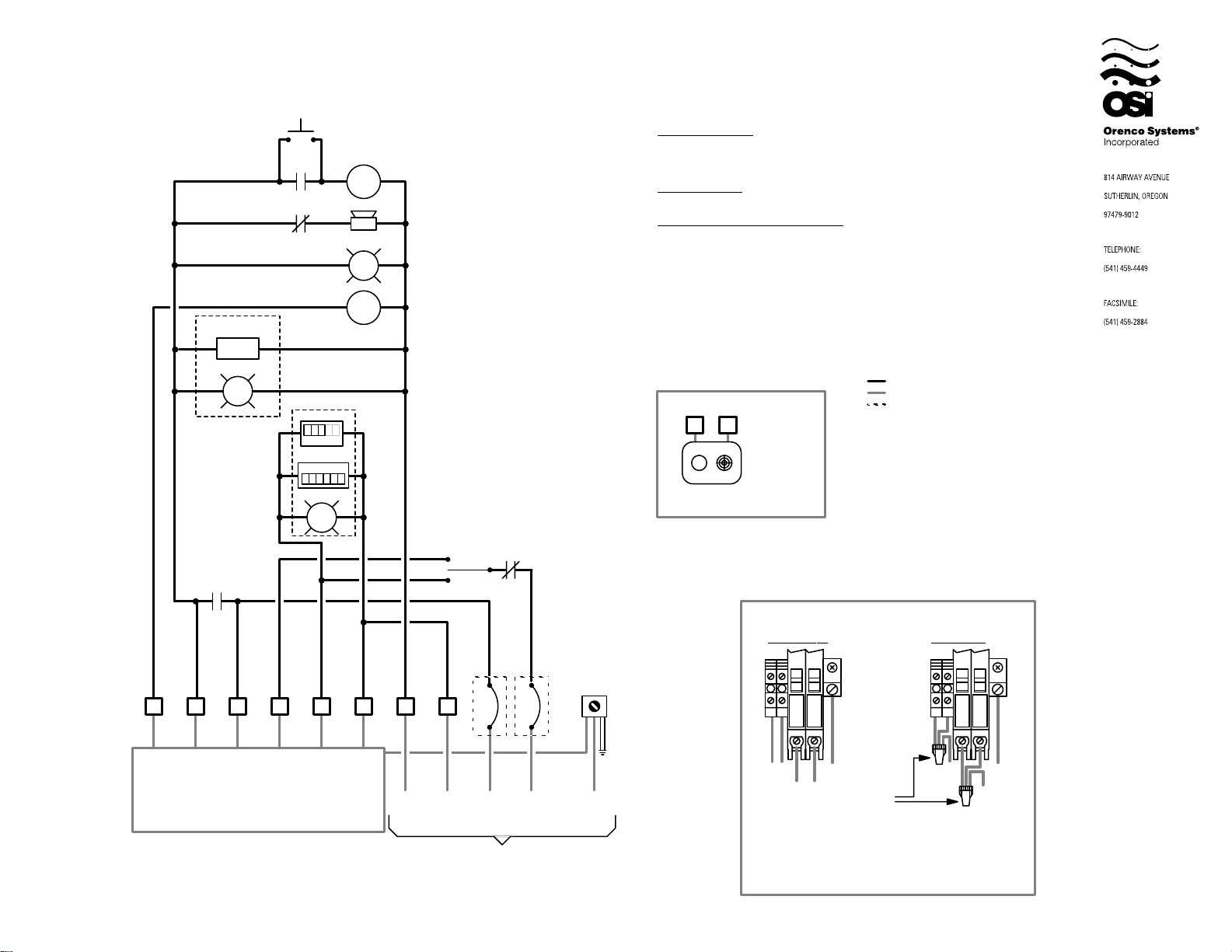
Panel Wiring Diagram
Model A1 RO
Options*
HT
G
CR1
9
6
PL
X2X1
AS
SR
9
SR
9
Options*
X1
5
14
+
1
00025
ETM
CT
999510
PRL
G
X2
SR
A
R
CR1
AL
X2X1
Simplex Operation
High Level Alarm: This float activates the alarm light and audible alarm
when lifted. The audible alarm may be silenced by pressing the illuminated
PUSH TO SILENCE button on the front of the control panel. The alarm
light will remain on until the float is lowered.
13
-
Pump On & Off: This float turns on the pump when lifted and off when
lowered.
Redundant Off & Low Level Alarm: This float turns off the pump when
lowered. This float is a secondary off float which will operate if the Pump
On & Off float fails. Pumping will be disabled in both the automatic and
manual modes. This float also activates the alarm light and audible alarm.
The audible alarm may be silenced by pressing the illuminated PUSH TO
SILENCE button on the front of the control panel. The alarm light will
remain on until the float is lifted.
BA
Key
= Factory Wire
= Field Wire
= Alternate Field Wire
= Audio Alarm, 115 VAC
A
= Alarm Light
AL
= Audio Silence Switch
AS
= Controls Circuit Breaker
CCB
= Redundant Off Relay
CR1
= Pump Circuit Breaker
PCB
= Silence Control Relay (1P)
SR
*Options
= Cycle Counter
CT
= Elapsed Time Meter
ETM
= Heater
HT
= Power Light
PL
= Pump Run Light
PRL
One Circuit
AUTO
MAN
1
CR1
Remote Alarm Connections
N
2
Remote Alarm
Light Alarm
Note: 115VAC signal is present
during alarm conditions.
OSI Model
AHW or equiv.
7
Power Wiring Options
Two Circuits
Terminal
Strip
2 3 4 5 6
1
For float arrangement
diagram, see
drawing no.
"EDW-FA-A-2"
NOTE: Motors must have
internal overload protection
N
Controls
Neutral
N1
Pump
Neutral
115 VAC, 1 Phase, 60 Hz.
From Main Power Panel
Main disconnect
provided by others.
10A
20A
Pump
L1
L1
PCB
CCB
Green
Ground
Lug
GroundControls
20
10
ON
ON
CONTROLS
PUMP
N1
N
Pump Neutral
Controls Neutral
Pump L1
Controls L1
Factory default.
Wire as shown.
N
Ground
Wire
Nut
Use one wire nut to connect the pole of
the pump circuit breaker together with
the controls breaker and with the
incoming L1 power line. Use another
wire nut to connect the neutral block of
the pump with the controls neutral block
and with the incoming neutral line.
20
10
ON
ON
CONTROLS
PUMP
N1
Neutral
Ground
L1
EDW-WD-A-2
Rev. 5.0 ©06/25/03
Page 4
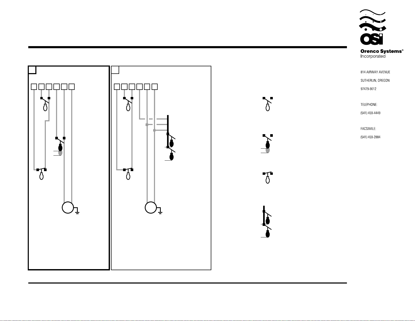
Float Arrangement Diagram
•
YGW
Factory Standard
•
Y(BR)W
2 64 51 2 3 64 5
3" Min.
115VAC, 1Hp, 1Ø, 60Hz Max.
230VAC, 1Hp, 1Ø, 60Hz Max.
Terminal Strip
High Level Alarm
Y-Yellow
Pump On & Off
G-Green
Redundant Off &
Low Level Alarm
W-White
Pump Motor
13
Black
115VAC, 1Hp, 1Ø, 60Hz Max.
230VAC, 1Hp, 1Ø, 60Hz Max.
Black/Red
White
Black
Red
White
Black
White
Pump Motor
Terminal Strip
2" Min.
High Level Alarm
Y-Yellow
Pump On & Off
(BR)-Blue & Red
Redundant Off &
Low Level Alarm
W-White
3" Min.
2" Min.
Float Types
Typical OSI float model: A
Specs: contact - normally open
differential - no minimum
power rating - signal
Possible substitutions: B,C,D
Typical OSI float model: B
Specs: contact - normally open
differential - 3" min.
power rating - pump
Possible substitutions: C,D
Typical OSI float model: T
Specs: contact - normally closed
differential - no minimum
power rating - signal
Typical OSI float model: K
Specs: contact - normally open
differential - 2" min.
power rating - pump
For a wire splicing illustration of the above
diagram, request Splice Box Wiring Diagram:
EDW-SB-A-4
Control Panel Series
A RO
For a wire splicing illustration of the above
diagram, request Splice Box Wiring Diagram:
EDW-SB-A-5
Drawing No.
EDW-FA-A-2
EDW-FA-A-2
Rev 2.1 ©11/16/98
Page 5
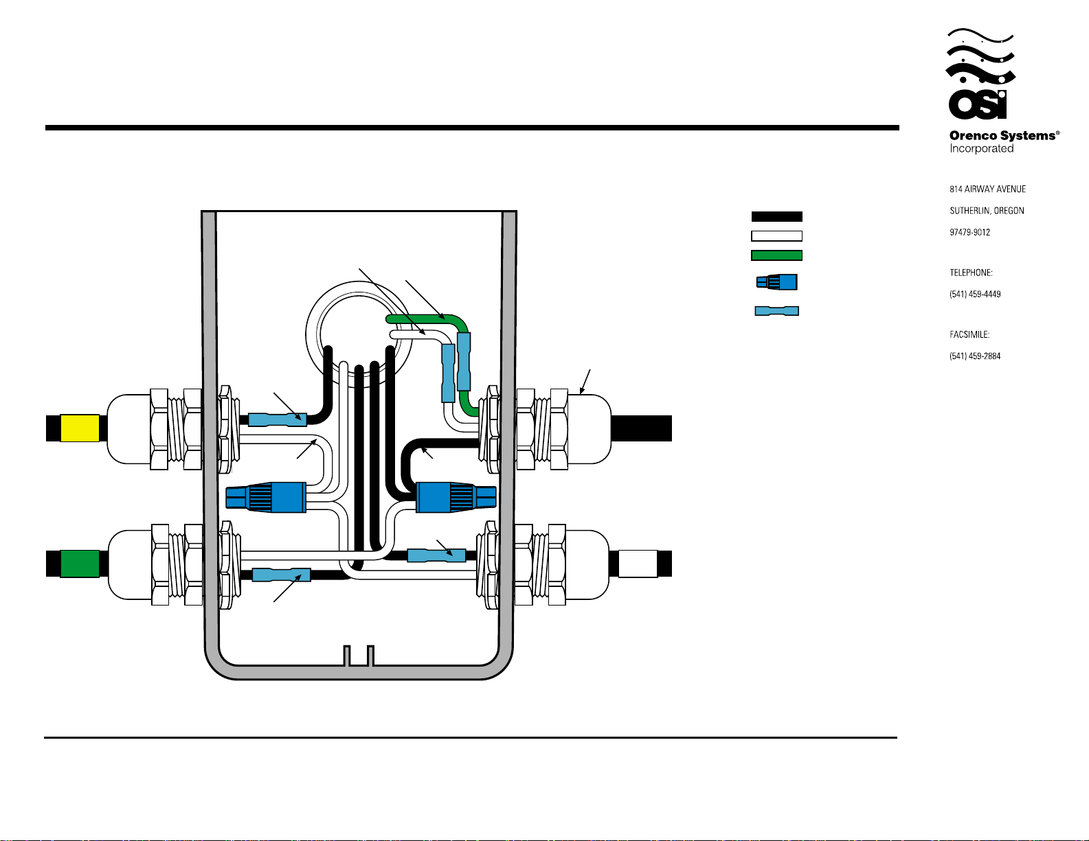
Splice Box Wiring Diagram
To Terminal
To Terminal
#2
Y
High Level Alarm Pump Cord
Pump On & Off Redundant Off &
To Terminal
#3
To Terminal
#4
To Ground
#6
Terminal
To Terminal
#5
To Terminal
#1
Low Level Alarm
Cord Grip
Hand tighten each cord grip
so that the cord will not easily
slide through the grommet.
WG
Key
Black Wire
White Wire
Green Wire
Waterproof
Wire Nut
Heat Shrink &
Butt Connector *
* Refer to drawing EIN-SB-SB-1
for splicing instructions.
Float Tag Colors
Yellow
-
Y
Purple
-
P
Blue
-
B
Green
-
G
Red
-
R
Orange
-
O
Grey
-
E
White
-
W
Note: Multi-function floats will
have more than one marker
Control Panel Series
A RO
Float Function Color Code
YGW
Splice Box Model
SB4
Attention: Failure to follow splicing
instructions will void warranty
Drawing No.
EDW-SB-A-4
EDW-SB-A-4
Rev 1.2 ©04/29/98
Page 6
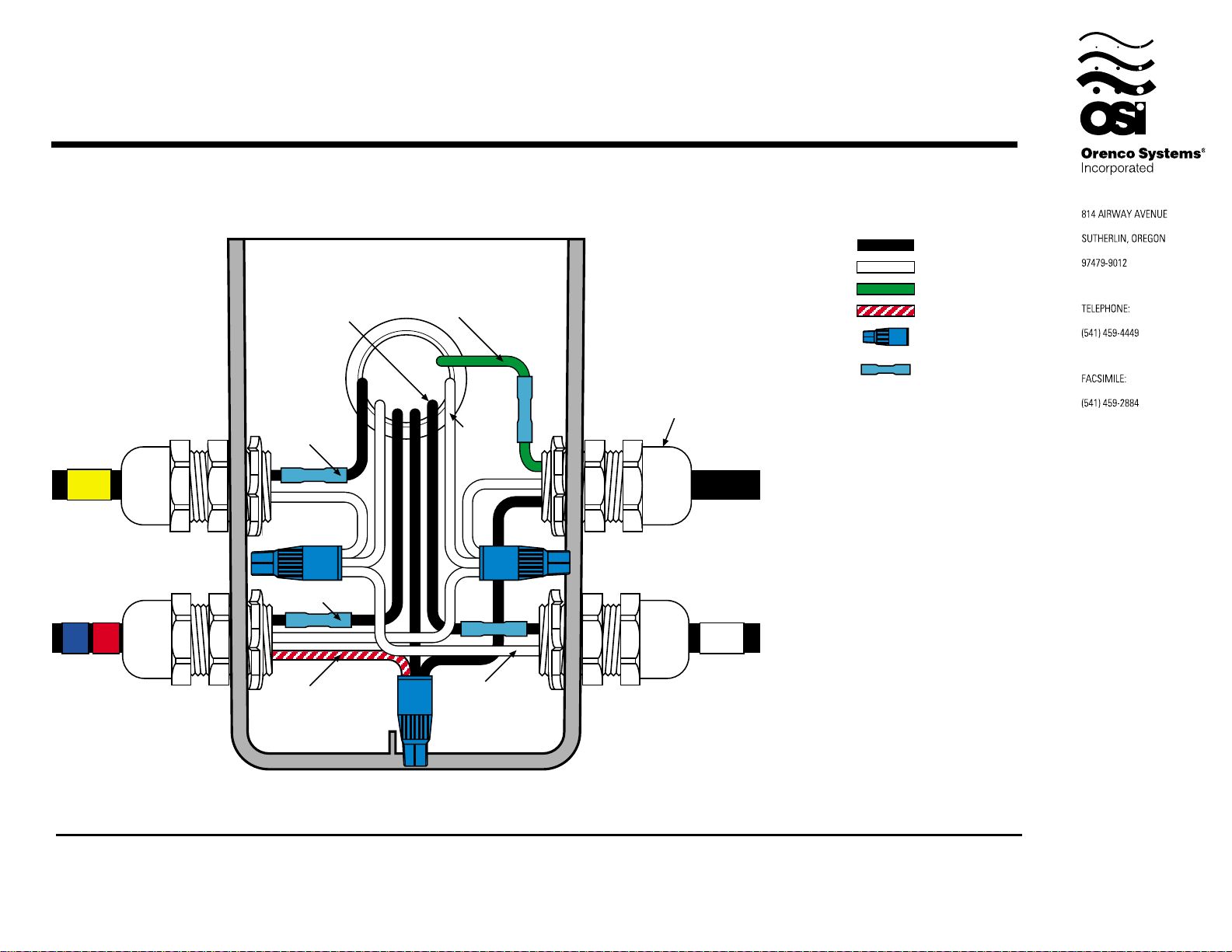
Splice Box Wiring Diagram
For use with double On & Off float system.
To Terminal
#1
To Terminal
#2
Y
High Level Alarm Pump Cord
To Terminal
#4
RB
Pump On & Off Redundant Off &
To Terminal
#5
To Ground
Terminal
To Terminal
#6
To Terminal
#3
Low Level Alarm
Cord Grip
Hand tighten each cord grip
so that the cord will not easily
slide through the grommet.
W
Key
Black Wire
White Wire
Green Wire
Red Wire
Waterproof
Wire Nut
Heat Shrink &
Butt Connector *
* Refer to drawing EIN-SB-SB-1
for splicing instructions.
Float Tag Colors
Yellow
-
Y
Purple
-
P
Blue
-
B
Green
-
G
Red
-
R
Orange
-
O
Grey
-
E
White
-
W
Note: Multi-function floats will
have more than one marker
Control Panel Series
A RO
Float Function Color Code
Y(BR)W
Splice Box Model
SB4
Attention: Failure to follow splicing
instructions will void warranty
Drawing No.
EDW-SB-A-5
EDW-SB-A-5
Rev 1.2 ©04/29/98
 Loading...