

Orenco Systems HV100, HV125, HV150, HV200 Installation Manual
© 2004 Orenco Systems®Inc. NIN-HV-HV-1
Rev 2.0, 3/04
Page 1 of 4
1
Discharge Plumbing Assemblies
Installation, Operation and Maintenance Instructions
Models HV100__, HV125__, HV150__, HV200__
Installation Instructions:
The Discharge Plumbing Assembly (a.k.a. “Hose & Valve” Assembly) is the route by which the effluent travels from the effluent
pump to the transport pipe. It is composed of rigid PVC pipe, a flexible PVC hose, a union, and a series of threaded elbows.
Options include ball valves, check valves, gate valves, external flex hose assemblies, and anti-siphon assemblies.
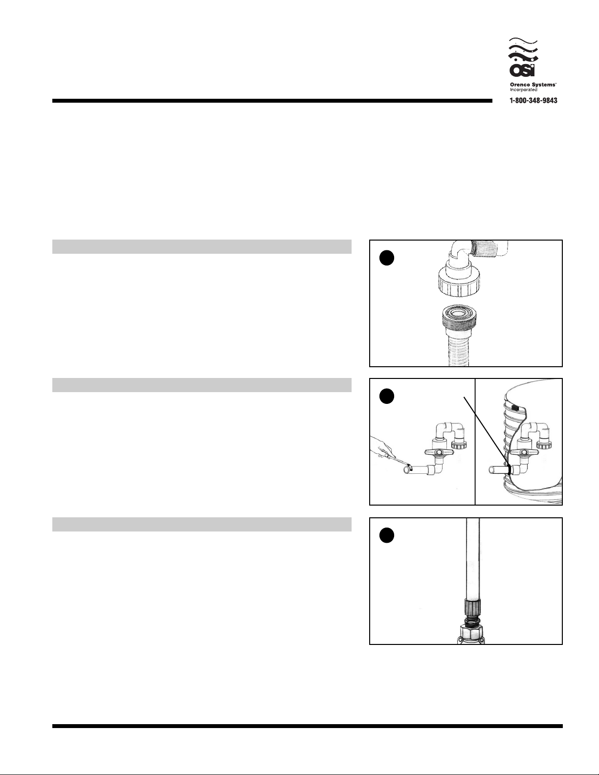
Step 1
Unscrew the union in the discharge plumbing assembly. Set the section
including the stem aside.
2
Step 2
Lubricate the pipe grommet in the access riser and the grey Schedule 80
nipple with petroleum jelly or an equivalent product. Push the nipple
through the pipe grommet, leaving as much of the nipple on the outside of
the riser as possible to minimize obstruction within the riser.
Grommet
3
Step 3
Screw the male adapter at the bottom of the discharge plumbing assembly
stem into the pump discharge.
© 2004 Orenco Systems®Inc.NIN-HV-HV-1
Rev 2.0, 3/04
Page 2 of 4
Installation Instructions (continued)
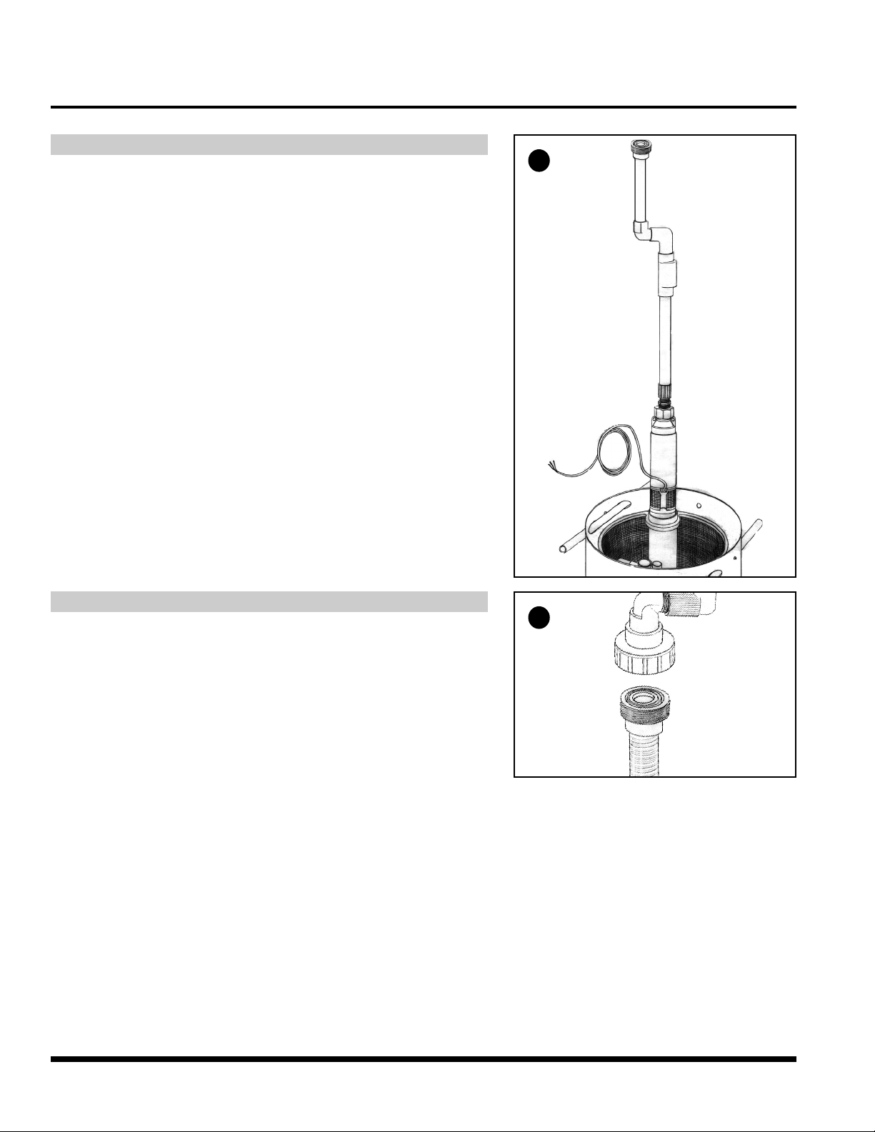
4
Step 4
Lower the pump into the screened pump vault. If the pump is a 4” diameter
turbine-style pump, make sure to lower the pump into the 4” PVC housing
attached to the screen (the flow inducer).
5
Step 5
Assemble the union.
Exercise the (optional) ball valve or gate valve by rotating the handle back
and forth to assure that there is enough operating room for the handle.
 Loading...