

Page 1
Long-Range Multi-Channel
In-Out Thermometer
with Cable Free Sensor and RF Clock
MODEL: RMR183/RMR183U
USER'S MANUAL
INTRODUCTION
Congratulations on your purchase of the RMR183/RMR183U
Long-Range (60 meters) Multi-Channel In-Out Thermometer with
433MHz cable free sensor and radio-controlled calendar clock.
The basic package comes with a main unit, which is the temperature
and calendar clock station, and a remote unit, the thermo sensor.
The main unit has a large display for indoor temperature,
calendar clock and temperatures collected and transmitted by the
remote unit. The main unit can support up to three remote units.
The main unit is capable of keeping track of the maximum and
minimum temperature of different sites. No wire installation is
required as the RMR183/RMR183U operates at 433MHz.
As for the calendar clock, it is radio-controlled. It automatically
synchronizes its current time and date when it is brought within
an approximate 1500km radius of the radio signal generated from
Frankfurt, Germany (DCF77) (or Radio signal MSF-60 from
Rugby, England for UK version).
You can also set the calendar clock manually when it is off range.
Other features include five-language display, crescendo daily
alarm and interchangeable display modes.
GB
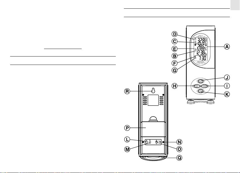
MAIN FEATURES: MAIN UNIT
1
Page 2

GB
A FOUR - LINE LCD DISPLA Y
Facilitates easy reading of remote and indoor temperatures and
calendar clock
] RADIO - RECEPTION SIGNAL
B[
Indicates the condition of radio reception
C TEMPERATURE TREND INDICATOR
Indicates the trend of temperature changes
D [ ] BATTERY - LOW INDICATOR
(REMOTE SENSOR)
Activates when the remote-sensor battery is low
E [ ] BATTERY - LOW INDICATOR
Activates when the battery of main unit is low
] ALARM - ON ICON
F[
Appears when the alarm is activated
(
)
G[ (
.
) ] ALARM ICON
Appears when the alarm time is displayed
H [ MODE ] BUTTON
Toggles the calendar clock display modes or activates the
calendar clock setting mode
I [ ALARM ] BUTTON
Displays the alarm time or sets the alarm status
J [MEMORY] BUTT ON
Displays maximum / minimum temperature
K [CHANNEL] BUTTON
Selects remote-sensor channels
L[
] BUTTON
Advances the value of a setting
M[
] BUTTON
Decreases the value of a setting
N [RESET] BUTTON
Returns all settings to default values
O °C/°F SLIDE SWITCH
Selects between degree Centigrade (°C) and Fahrenheit (°F)
P BATTERY COMP ARTMENT
Accommodates two (2) UM-3 or “AA” size 1.5V batteries
Q REMOV ABLE TABLE STAND
For standing the main unit on a flat surface
R WALL - MOUNT HOLE
For mounting the main unit on a wall
2
Page 3

MAIN FEATURES: REMOTE UNIT THN128
A LED INDICA TOR
Flashes when the remote sensor transmits a reading
B CHANNEL SLIDE SWITCH
Designates the remote sensor Channel
C RESET BUTTON
Returns all settings to default values
D BA TTERY COMP ARTMENT
Accommodates two (2) UM-4 “AAA” size 1.5V batteries
E BATTERY DOOR
F WALL-MOUNT HOLDER
Supports the remote unit in wall-mounting
G REMOV ABLE TABLE ST AND
For standing the remote unit on a flat surface
BEFORE YOU BEGIN
For best operation,
1. Assign different channels to different remote units.
2. Insert batteries for remote units before doing so for the main
unit.
3. Place the main unit as close as possible next to the remote unit
and reset the main unit after installing batteries. This will
ensure easier synchronization between the transmission and
reception of signals.
4. Position the remote unit and main unit within effective transmission range, which is 60 meters in open area.
3
GB
Page 4
GB
Note that the effective range is vastly affected by the building
materials and where the main and remote units are positioned. Try
various set-ups for best result.
Though the remote units are weather proof, they should be placed
away from direct sunlight, rain or snow.
Note:
1. Replace batteries when the low-battery indicator of a
particular channel activates on the main unit.
2. Once a channel is assigned to a remote unit, it can only be
changed by removing the batteries or resetting the unit.
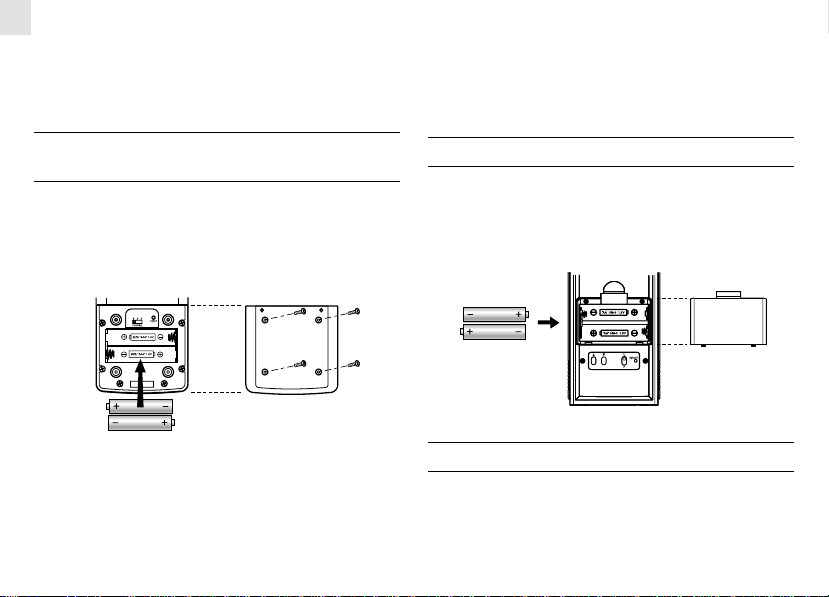
BATTERY INSTALLATION AND
CHANNEL SETTING: REMOTE UNIT
The remote unit uses two (2) UM-4 or “AAA” size 1.5V batteries.
Installation:
1. Remove the screws on the battery compartment.
2. Select the channel on the CHANNEL slide switch.
3. Insert the batteries strictly according to the polarities shown.
4. Replace the battery compartment door and screws.
BATTERY INSTALLATION: MAIN UNIT
1. Open the battery compartment door.
2. Install 2 batteries (UM-3 or “ AA” size 1.5V) strictly according
to the polarities shown.
3. Replace the battery compartment door.
LOW BATTERY WARNING
When it is time to replace batteries, the low-battery indicator will
show up when the corresponding channel is selected. The battery
level of the main unit will be shown on the indoor temperature
when it is running low.
4
Page 5

HOW T O USE THE TABLE STAND
OR WALL MOUNTING
The main unit has a removable table stand, which when installed,
can support the unit on a flat surface. Or you can remove the stand
and mount the unit on a wall using the recessed screw hole.
As for the remote unit, it comes with a wall-mount holder and a
removable stand. Use either to hold the unit in place.
Main unit
Wall-mount T able Stand
Remote unit
W all-mount Table Stand
THE RESET BUTTON
This button is only used when the unit is operating in an unfavorable way or malfunctioning. Use a blunt stylus to hold down the
button. All settings will return to their default values.
GETTING STARTED
Once batteries are in place for the remote units, they will start
transmitting temperature readings at 30 second intervals.
The main unit will also start searching for signals for about a
minute once batteries are installed. Upon successful reception,
the individual channel temperatures will be displayed on the top
line and the indoor temperature on the second line. The main unit
will automatically update its readings at about 30-second intervals.
If no signals are received, blanks "----" will be displayed and the
kinetic wave icon will show "
[MEMORY] simultaneously to enforce another search for about
30 seconds. This is useful in synchronizing the transmission and
reception of the remote and main units.
Repeat this step whenever you find discrepancies between the
reading shown on the main unit and that on the corresponding
remote unit.
5
". Press [CHANNEL] and
GB
Page 6

GB
HOW TO CHECK REMOTE AND
INDOOR TEMPERATURES
The indoor temperature is shown on the second line of the display .
As for the remote sites or channels, press [CHANNEL] to go from
one channel to another. The kinetic wave display on the channel
number indicates if the reception of that particular channel is in
good order.
If no readings are received from one particular channel for more
than two minutes, blanks “---” will be displayed until further
readings are successfully searched. Check if the remote unit
is sound and secure. You can wait for a little while or press
[CHANNEL] and [MEMORY] simultaneously to enforce an
immediate search. Of course no reading will be shown if no remote
unit is assigned to that channel.
If the temperature goes above or below the temperature measuring
range of the main unit or the remote unit (stated in specification),
the display will show “HHH” or “LLL”.
TEMPERATURE TREND
The temperature trend indicator on the screen shows the trend of
samplings collected at that particular remote site. Three trends,
rising, steady and falling, will be shown.
Arrow
indicator
Temperature
Trend
Rising Steady Falling
MAXIMUM AND MINIMUM
TEMPERATURES
The maximum and minimum recorded indoor temperatures and
those of outdoor channels will be automatically stored in memory.
To display them:
1. Select the channel to be checked.
2. Press [MEMORY] once to display the maximum temperature
and again the minimum temperature. The respective indicators,
MAX or MIN will be displayed.
T o clear the memory, hold down [MEMORY] for two seconds. The
maximum and minimum temperatures will be erased. If you press
[MEMORY] now, the maximum and minimum temperatures will
have the same values as the current ones until different readings
are recorded.
NOTE ON °C AND °F
The unit of temperature display is selected with the °C/°F slide
switch. Select °C for Centigrade or °F for Fahrenheit.
HOW TO READ
THE KINETIC WAVE DISPLAY
The kinetic wave display shows the signal receiving status of the
main unit. There are three possible forms:
6
Page 7

The unit is in searching mode.
transmission and reception of temperature readings will resume
once the interference recedes.
GB
Temperature readings are
securely registered.
No signals.
DISCONNECTED SIGNALS
If without obvious reasons the display for a particular channel
goes blank, press [CHANNEL] and [MEMORY] to enforce an
immediate search. If that fails, check:
1. The remote unit of that channel is still in place.
2. The batteries of both the remote unit and main unit. Replace as
necessary.
Note: When the temperature falls below freezing point, the
batteries of outdoor units will freeze, lowering their voltage
supply and the effective range.
3. The transmission is within range and path is clear of obstacles
and interference. Shorten the distance when necessary.
TRANSMISSION COLLISION
Signals from other household devices, such as door bells, home
security systems and entry controls, may interfere with those of
this product and cause temporary reception failure. This is normal
and does not affect the general performance of the product. The
CALENDAR AND ALARM TIME DISPLAY
The calendar and alarm time share the same section of display. The
calendar is displayed in day-month format. When the calendar is
displayed, pressing [ALARM] once will change the display to the
alarm time. Another press on the button will acti v a te the alarm. A
third press will deactivate it.
To display the calendar, press [MODE] once.
Calendar mode Alarm mode
ABOUT RADIO RECEPTION
The RMR183/RMR183U is designed to automatically synchronize
its calendar clock once it is brought within range of the Frankfurt
DCF77 radio signal. (Rugby MSF-60 Radio signal for UK version).
When the RMR183/RMR183U is within range, the radio-controlled mechanism will override all manual settings.
When the unit is receiving radio signal, the radio-reception Signal
will start to blink. Generally, complete reception take 2 to 10
minutes depending on the strength of the radio signal.
7
Page 8

GB
When the reception is complete, the radio-reception Signal will
stop blinking.
- Strong
- W eak
- No Reception
- Receiving
For better reception, place the unit away from metal objects and
electrical appliances to minimize interference.
If you wish to disable the auto-reception feature, press the [ ] and
[
] buttons simultaneously for two seconds. The radio-reception
Signal [
] will disappear. The unit will not respond to radio
signals.
To enable the feature again, hold down the [
] and [ ] buttons
again. The radio-reception signal will start blinking to initiate
reception automatically.
HOW TO SET THE CALENDAR CLOCK
MANUALLY
When the calendar is displayed, press [MODE] for two seconds.
The month digits will start to blink.
Enter the month using the [
button to rapidly increase or decrease the value.
Press [MODE] to confirm and proceed to set the day, display
language, day-of-the-week, hour and minute.
For the display language, you can choose between English (E),
German (D), French (F), Italy (I), Spanish (S).
The day-of-the-week display for the languages is as follows:
Language
After setting the minutes, press [MODE] to return to normal
display. If changes are made on the minutes, the seconds will reset
Monday Tuesday Wed. Thursday Friday Saturday Sunday
English
German
French
Italian
Spanish
and start from zero.
8
] and [ ] buttons. Hold down either
Day-of-the-week
Page 9

TIME DISPLAY MODE
When the display is in calendar mode, press [MODE] once to
change between the hour, minute, seconds display to hour, minute,
Day-of-Week display.
Hour-Minute-Second Hour-Minute-Day
HOW TO SET AND ACTIVATE
THE ALARM
While in alarm mode, press and hold [ALARM] for two seconds
the hour digits will flash.
Enter the value for the hour digits. Press [ALARM] to confirm and
go to the minute digits. Enter the value and press [ALARM] to
confirm.
The alarm is automatically activated. To deactivate it, press
[ALARM] once.
To stop the alarm, press any key (except [MEMORY] and
[CHANNEL] ) .
PRECAUTIONS
This product is engineered to give you years of satisfactory
service if you handle it carefully. Here are a few precautions:
1. Do not immerse the unit in water.
2. Do not clean the unit with abrasive or corrosive materials. The y
may scratch the plastic parts and corrode the electronic circuit.
3. Do not subject the unit to excessive force, shock, dust,
temperature or humidity, which may result in malfunction,
shorter electronic life span, damaged battery and distorted
parts.
4. Do not tamper with the unit's internal components. Doing so will
invalidate the warranty on the unit and may cause unnecessary
damage. The unit contains no user-serviceable parts.
5. Only use fresh batteries as specified in the user's manual. Do not
mix new and old batteries as the old ones may leak.
6. Always read the user's manual thoroughly before operating the
unit.
GB
ALARM FUNCTION
When the alarm is active, it will go off at the set time with the
ALARM ON icon flashing.
The crescendo function allows the alarm to start off gently and
step up its intensity in three steps. Without interruption, the
alarm will go off for a minute and will go off once again after
approx. 8 minutes.
SPECIFICATIONS
Temperature Measurement
Main unit
Indoor Temperature measurement
Operating range : -5.0°C to +50.0°C
(23.0°F to 122.0°F)
9
Page 10

GB
Temperature resolution : 0.1°C (0.2°F)
Remote unit
Proposed operating range : -20.0°C to +60.0°C
(-4.0°F to 140.0°F)
Temperature resolution : 0.1°C (0.2°F)
RF Transmission Frequency : 433 MHz
No. of Remote unit : Maximum of 3
RF Transmission Range : Maximum 60 meters
Temperature sensing cycle : around 30 seconds
Radio Controlled Clock
Radio Control : Auto synchronize
Calendar : Day of week in English,
Clock Time : 24 hour format
Alarm Duration : 1 minute crescendo
Snooze : 8 minutes
current time and date by
Radio signal generated
from Germany DCF77
or MSF-60 from UK for
UK version
German, French, Italy or
Spanish, Day/Month
12 hour format
(UK version)
Accuracy : +/-0.5 second/day
(when RF is disabled)
Power
Main unit : use 2 pcs UM-3 or “AA”
Remote sensing unit : use 2 pcs UM-4 or “AAA”
1.5V battery
1.5V battery
Weight
Main unit : 154 gm (without battery)
Remote sensing unit : 56.2 gm (without battery)
Dimension
Main unit : 187(L) x 70(W) x 20(T) mm
Remote sensing unit : 92(L) x 60(W) x 21 (T) mm
CAUTION
-
The content of this manual is subject to change
without further notice.
-
Technical features of this product is subject to change
without notice.
-
Due to printing limitation, the displays shown in this
manual may differ from the actual display.
-
The contents of this manual may not be reproduced
without the permission of the manufacturer.
10
Page 11

EC-DECLARATION OF CONFORMITY
This product contains the approved transmitter module TX 01 and complies
with the essential requirements of Article 3 of the R&TTE 1999/5/EC
Directives, if used for its intended use and that the following standard(s)
has/have been applied:
Efficient use of radio frequency spectrum
(Article 3.2 of the R&TTE Directive)
applied standard(s) EN 300 220-1(2,3):1997
Electromagnetic compatibility
(Article 3.1.b of the R&TTE Directive)
applied standard(s) ETS 300 683:1997
Safety of information technology equipment
(Article 3.1.a of the R&TTE directive)
applied standard(s) EN 60950:1997
Additional information:
The product is therefore conform with the Low Voltage Directive 73/23/EC,
the EMC Directive 89/336/EC and R&TTE Directive 1999/5/EC (appendix
II) and carries the respective CE marking.
VS-Villingen / Germany August 2001
Gerhard Preis
R&TTE Representative of manufacturer
RTTE Compliant Countries :
All EC countries, Switzerland CH
And Norway N
GB
11
Page 12

GB
Trouble
“---” is being displayed for
Remote data on the display of
the Main Unit
Displayed remote temperature
and/or humidity data on the
display of the Main Unit are
different from those on the
display of the Remote Sensor
The added Remote sensor is not
read by main unit
Displayed Temperature and/or
humidity data are different
from other measuring
instruments
TROUBLESHOOTING GUIDE — RMR183
Possible Cause
(1) Probably due to electromagnetic
interference and/or obstacle in-between
the Main Unit and Remote Sensor (e.g.,
double glass protection or reinforced
concrete wall); or
(2) Batteries of the Remote Sensor are being
discharged
Another Remote Sensor using the same
frequency and same ID code is being in use
within the effective area
Selected Channel is already used by another
Remote sensor
(1) The measurement method is different
(2) The area under evaluation is different or
being influenced by climate
12
(1) (i) Move the Main Unit away from any
source of interference such as DECT
phone, mobile phone; and/or (ii) Move
the Remote sensor nearer to the main
unit and start SEARCH mode in the
Main Unit
(2) Check LED of Remote Sensor. Replace
with new batteries if it does not flash
in one minute
Place the Remote Sensor closer to the Main
Unit. Then reset the Remote Sensor and
activate SEARCH mode in the Main Unit
Select another free channel via the Channel
switch. Then reset the Remote Sensor and
activate SEARCH mode in the Main Unit
(1) Use the same instruments with
consideration of the tolerance of
readings
(2) Place the 2 instruments very closely for
a time period (no less then 30 minutes),
avoiding direct light and air movements
Remedy
Page 13

Trouble
- Clock time is not correctly
set; and/or
- Reception icon “Antenna”
displays as “No reception”
The clock radio signal is not received because:
- Electromagnetic interference exist, or the
Main Unit is located within reinforced
concrete wall or shadowed area location
Possible Cause
- Orientation of placement is not at
optimum position for reception of clock
radio signal
Warning:
- For other cases not listed in the a bove, feel free to contact our help line
- Do not dissemble the unit. This will void the warranty
13
Remedy
- Locate the Main Unit far from PC,
mobile phone etc and re-locate it near
the window sill. Wait at least 24 hours
(note: during night-time signal is less
attenuate particularly after raining)
- The clock radio signal is searched at
1:00, 2:00, 3:00, 9:00, 15:00, 21:00
every day automatically
- To force the signal reception please refer
to instructions in the User’s manual
GB
 Loading...