

Page 1

DIGITAL WEATHER FORECASTER
WITH REMOTE THERMO-SENSOR AND
RADIO CONTROLLED CLOCK
MODEL: BAR113
USER’S MANUAL
( FOR USE IN UK & IRELAND ONLY )
MAIN FEATURES: MAIN UNIT
433MH CABLE FREE
Z
GB
INTRODUCTION
Congratulations on your purchase of the Weather forecaster with
cable free sensor and radio-controlled calendar clock (BAR113).
A multifunction device, this unit has a large four-line liquid
crystal display (LCD) for displaying weather forecast information,
in/outdoor temperatures, a radio frequency (RF) controlled calendar
clock, time zone adjusted time, and dual daily alarms. Also, it can
display temperature readings from up to three wireless remote
thermo-sensors.
Other features include a day-of-the-week display in four abbreviated
languages, a four-step crescendo alarm, and interchangeable clock
display modes.
CHANNELMEMMODE / S ET
AL°C
RESET
ON/OFF
°F
1
Page 2
GB
A . FRONT DISPLAY
A four line easy-to-read LCD each with specific purposes that
relate to weather forecasting, temperature, or clock / calendar
/ alarm functions.
A1 . WEATHER FORECAST WINDOW
- Graphically illustrates a weather forecast
A2. REMOTE TEMPERATURE WINDOW
- Displays current temperature, remote sensor unit
- Indicates the minimum / maximum remote temperature
- Displays remote temperature as Fahrenheit (°F) or Celsius (°C)
- Indicates when the remote sensor battery is low
- Indicates the remote sensor channel
A3. INDOOR TEMPERATURE WINDOW
- Displays current indoor temperature
- Indicates minimum / maximum indoor temperature
- Displays indoor temperatures as Fahrenheit (°F)/ Celsius (°C)
- Indicates when main unit battery is low
A4. TIME / DATE / ALARM WINDOW
- Displays the current time, date (day, month, and day-of-the-
week), or alarm times
- Current time and date in another time Zone
- Radio Frequency (RF) status indicator [
]
- “ALARM ON” icon indicates when the alarm is active [
- Alarm indicator [ ]
B. CONTROL BUTTONS
B1. CHANNEL BUTTON
Sets the remote sensor channel.
B2. [MEM] BUTTON
Displays minimum and maximum temperature readings, and
erases memory data
B3. ALARM [
] BUTTON
Displays the alarm time, or changes the alarm set time
B4. MODE/SET BUTTON
Changes the display mode of the clock, and alters time/date
setting
B5. UP [
] DOWN [ ] BUTTONS
Sets the increase or decrease in the value of a setting.
B6. [AL ON/OFF] BUTTON
Activates and deactivates the alarm
B7. °C/°F SLIDE SWITCH
Selects between Centigrade (°C) or Fahrenheit (°F) display
C. OTHER FEATURES
C1. BATTERY COMPARTMENT
Accommodates four UM-3 or “AA” size alkaline batteries
C2. RESET SLOT
Resets the unit by returning all setting to their default values
C3. REMOVABLE TABLE STAND
]
For mounting the remote sensor on a flat horizontal surface.
C4. RECESSED WALL-MOUNT HOLE
For mounting to a wall or vertical surface
2
Page 3

MAIN FEATURES:
REMOTE SENSOR UNIT
The remote sensor is a wireless independent component. Its function
is to monitor temperatures at a location other than the location of
the main unit.
A . LED INDICATOR
GB
Flashes when the remote sensor transmits a reading
B. CHANNEL SLIDE SWITCH
Designates the remote sensor Channel
C . RESET BUTTON
Returns all settings to default values
D. BATTERY COMPARTMENT
Accommodates two (2) UM-4 “AAA” size batteries
E. BATTERY DOOR
F. WALL-MOUNT HOLDER
Supports the remote unit in wall-mounting
G. REMOVABLE TABLE STAND
For standing the remote unit on a flat surface
BEFORE YOU BEGIN
For best operation:
Insert batteries for the remote unit first. Then proceed with inserting
the batteries for the main unit.
Position the remote unit and the main unit within effective
transmission range. In usual circumstances, the effective range is
30 meters.
Though the remote unit is weather proof, it should be placed away
from direct sunlight, rain or snow.
3
Page 4
GB
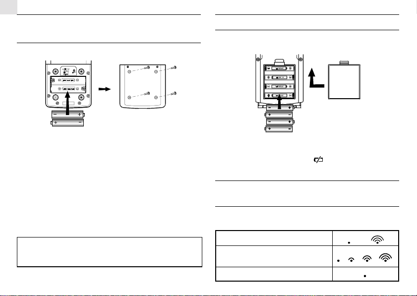
BATTERY INSTALLATION:
REMOTE UNIT
The remote unit uses two UM-4 or “AAA” size alkaline batteries.
BATTERY INSTALLATION: MAIN UNIT
1. Gently lift the tab on the battery compartment door.
2. Insert four UM-3 or “AA” size alkaline batteries.
Installation:
1. Remove the screws on the battery compartment.
2. Select the desired temperature scale by switching the °C/°F
switch located inside the battery compartment.
3. Select the channel number on the CHANNEL slide switch. Note
that once a channel is assigned to a remote unit, you can only
change it by removing the batteries or resetting the unit.
4. Insert the batteries strictly according to the polarities shown
inside the battery compartment.
5. Replace the battery compartment door and secure the screws.
Note: Disposed of improperly, batteries can be harmful.
Protect the environment by taking exhausted batteries to
authorized disposal stations.
3. Replace the battery compartment door.
Note: For both the remote sensor and the main unit, replace batteries when
they are low. The low battery indicator [ ] in the indoor or / and outdoor
temperature window will be displayed when the batteries are low.
HOW TO READ THE KINETIC
WAVE DISPLAY
The kinetic wave display shows the signal receiving status of the
main unit. There are three possible forms:
The unit is in searching mode.
Channel registered in search mode.
No signal received in search mode.
4
Page 5

MAXIMUM AND MINIMUM
TEMPERATURES
The maximum and minimum recorded temperatures will be
automatically stored in memory. To display them, press MEM.
Press MEM again to alternate between the maximum, minimum,
and current temperatures. The respective MAX or MIN indicator
will be displayed.
To clear the memory, press MEM button and hold for three seconds.
The maximum and minimum-recorded temperatures will be erased.
Subsequently, if you press MEM after the memory has been erased,
the maximum and minimum temperature will have the same values
as the current reading.
DISCONNECTED SIGNALS
If without obvious reasons the display for a particular channel
goes blank, press CHANNEL and MEM simultaneously to enforce
an immediate search. If that fails, check:
1. The remote unit of that channel is still in place
2. The batteries of both the remote unit and main unit. Replace if
necessary.
Note: When the temperature falls below freezing point, the
batteries of outdoor units will freeze lowering their voltage
supply and the effective range.
3. The transmission is within range and the path is clear of obstacles
and interference.
Shorten the distance when necessary.
TRANSMISSION COLLISION
Signals from other household devices, such as door bells, home
security systems and entry controls, may interfere with those of
this product and cause temporarily reception failure. This is normal
and does not affect the general performance of the product. The
transmission and reception of temperature readings will resume
once the interference recedes.
NOTE ON °C AND °F
The unit of temperature display is selected on the °C/°F slide
switch. Select °C for Centigrade or °F for Fahrenheit.
Note: The remote temperature display on the main unit is dominated
by the selection on the °C/°F slide switch of the main unit. Whatever
the display units of the remote sensors, they will be automatically
converted to the choice of the main unit.
WEATHER FORECAST FUNCTION
The unit is capable of detecting atmospheric pressure changes.
Based on collected data, it can predict the weather for the forthcoming
12 to 24 hours. The effective range covers an area of 30 to 50 km.
Indicator
displays
on the unit
Slightly Cloudy
5
CloudySunnyForecast
Rainy
GB
Page 6

GB
NOTE:
1. The accuracy of a general pressure-based weather forecast is
about 70% to 75%.
2. The weather forecasts from this unit are predictions that cover
the next 12 to 24 hours. It may not necessarily reflect the current
situation.
3. The “Sunny” icon, as applies to nighttime, implies clear weather.
CALENDAR CLOCK DISPLAY MODES
The BAR113 supports four time display modes in the sequence of:
MODE 1.
MODE 2.
MODE 3.
Hour-Minute
Hour-Minute-Second (of local time)
Day-Month (of local time)
Hour-Minute-Day of the Week (of local time)
Day-Month (of local time)
Hour-Minute-Day of the Week (of local time)
MODE 4.
Day-Month
Each press on the MODE button will toggle the display in the
above order.
Note: The bottom line of the display will be replaced by the alarm
time if the ALARM [
Hour-Minute-Day of the Week
] button is pressed.
ABOUT RADIO RECEPTION
The BAR113 is designed to automatically synchronize its calendar
clock once it is brought within range of the UK Rugby MSF-60
radio signal.
When the BAR113 is within range, its radio-control mechanism
will override all manual settings.
When the unit is receiving radio signal, the RADIO RECEPTION
signal will start to blink. A complete reception generally takes
about two to 10 minutes, depending on the strength of the radio
signal.
When the reception is complete, the RADIO RECEPTION signal
will stop blinking. The strength of the reception will remain until
the next scanning cycle backs place.
For better reception, place the clock away from metal objects and
electrical appliances to minimize interference.
6
Page 7

-
Strong
-
Weak
-
No signal
-
Receiving
If you wish to disable the auto-reception feature, press the
button for three seconds. The radio reception signal [ ]will disappear.
The unit will not respond to radio signals.
To enable the feature again, press the
The radio reception signal [
button for three seconds.
] will start blinking to initiate
reception automatically.
HOW TO SET THE CLOCK MANUALLY
To set the clock manually, hold MODE/SET for three seconds. The
hour digits will blink.
or select the hour. Keep pressing the button to in-
Press
crease or decrease the value rapidly.
Press MODE/SET to confirm. The minute digits will blink.
Repeat the same procedure to set the minutes, current date, month,
display language, day-of-week and offset for the alternate time
zone.
Note: The time and date are displayed in 12-HOUR clock format.
For the language display, you can choose among English (E),
German (D), French (F) and Italian (I). Day-of-week is in the usual
sequence of Monday through Sunday.
For the alternate time zone, which is indicated by the ZONE icon,
enter the hour offset using the
and buttons and the BAR113
will calculate the second time accordingly.
If there is an item you do not wish to change, simply press MODE/
SET to bypass the item.
When you are done, press MODE/SET to exit. The display will
return to the mode last chosen.
HOW TO SET AND ARM THE ALARMS
The BAR113 has two alarms, ALARM 1 and ALARM 2. They can be
invoked together or independently.
7
GB
Page 8

GB
To set an alarm:
1.
Press [ ] once to select ALARM 1 or again to select ALARM 2
the last selected time of the alarm will be displayed. If you have
never set the alarm before, the time will be displayed as 12:00am.
2.Press [
3.Enter the hour using
4.Press [
5.Enter the minutes using
6.Press [
be displayed indicating the alarm set above is now armed.
You can also arm or disarm an alarm by pressing the [AL ON/OFF]
button.
When an alarm is armed, it will go off at the set time.
The four-step crescendo function allows the alarm to start off
gently and step up its intensity. Without interruption, the alarm
will go off for a total of two minutes.
If a second alarm goes off when the first alarm is sounding off, the
first alarm will be disabled automatically.
] for three seconds. The hour digits will blink.
and .
]. The minute digits will blink.
and .
] to exit. The [ ] icon for the alarm chosen will
HOW TO STOP AN ALARM
To stop an alarm, you can use either press [ ] button or [AL ON/
OFF] button.
Pressing [
armed and will activate at the set time the following day.
If [AL ON/OFF] button is pressed again, the alarm will be stopped
and deactivated all together.
] or [AL ON/OFF] will stop the alarm, which is still
NOTE ON OUTDOOR-REMOTE
TEMPERATURE
Once batteries are in place in the remote unit, it will start
transmitting samplings at 30-second intervals.
If no signals are received when the outdoor-remote temperature is
selected, “
search for remote sensor signals, press MEM and CHANNEL
buttons simultaneously.
If that fails, check that the remote sensor is still in place. Make sure
the transmission is within range and the path is clear of obstacles
and interference.
” will be displayed. To force the main unit to
NOTE ON SETTING REMOTE SENSOR
CHANNELS
The unit has an auto-scan function that sequentially displays
temperature readings of up to three remote sensors. In order to
function properly, each remote sensor must be set to different
channels.
THE RESET BUTTON
The button is only used when the unit is operating in an unfavorable
way or malfunctioning. Use a blunt stylus to hold down the button.
All settings will return to their default values.
8
Page 9

HOW TO WALL-MOUNT OR USE THE
TABLE STAND
The unit can be wall-mounted using its recessed screw holes or
place on a flat surface by attaching the table stand.
Main Unit:
Wall-mount Table
Stand
433MH CABLE F REE
Z
CHANNELMEMMO DE / SET
Remote Sensor:
The sensor comes with a wall-mount holder and a removable stand.
Use either to hold the unit in place.
Stand
Wall-mount Table
GB
MAINTENANCE
When handled properly, this unit is engineered to give you years
of satisfactory service. Here are a few product care instructions:
1. Do not immerse the unit in water. If the unit comes in contact
with water, dry it immediately with a soft lint-free cloth.
2. Do not clean the unit with abrasive or corrosive materials.
Abrasive cleaning agents may scratch the plastic parts and
corrode the electronic circuit.
3. Do not subject the unit to excessive: force, shock, dust,
temperature, or humidity. Such treatment may result in
malfunction, a shorter electronic life span, damaged batteries, or
distorted parts.
4. Do not tamper with the unit’s internal components. Doing so
will terminate the unit’s warranty and may cause damage. The
unit contains no user-serviceable parts.
5. Only use new batteries as specified in this instruction manual.
Do not mix new and old batteries as the old batteries may leak.
6. Read this instruction manual thoroughly before operating the
unit.
9
Page 10

GB
SPECIFICATIONS
Temperature Measurement
Main unit
Indoor Temperature measurement
Proposed operating range : -5.0°C to +50.0°C
(23.0°F to 122.0°F)
Temperature resolution : 0.1°C (0.2°F)
Remote unit
Proposed operating range : -20.0°C to +60.0°C
(-4.0°F to 140.0°F)
Temperature resolution : 0.1°C (0.2°F)
RF Transmission Frequency : 433 MHz
RF Transmission Range : Maximum 30 meters
Temperature sensing cycle : around 30 seconds
Power
Main unit : use four (4) UM-3 or “AA”
1.5V alkaline battery
Remote sensing unit : use two (2) UM-4 or “AAA”
1.5V alkaline battery
Weight
Main unit : 189gm (without battery)
Remote sensing unit : 70 gm
Dimension
Main unit : 161 x 87 x 28 mm(L x Wx D)
Remote sensing unit : 92 x 60 x 21mm (L x Wx D)
CAUTION
— The content of this manual is subject to change without
further notice.
— Due to printing limitation, the displays shown in this
manual may differ from the actual display.
— The contents of this manual may not be reproduced
without the permission of the manufacturer.
10
Page 11

EC-DECLARATION OF CONFORMITY
This product contains the approved transmitter module TX 01 and
complies with the essential requirements of Article 3 of the R&TTE
1999/5/EC Directives, if used for its intended use and that the
following standard(s) has/have been applied:
Efficient use of radio frequency spectrum
(Article 3.2 of the R&TTE Directive)
applied standard(s) EN 300 220-1(2,3):1997
Electromagnetic compatibility
(Article 3.1.b of the R&TTE Directive)
applied standard(s) ETS 300 683:1997
Safety of information technology equipment
(Article 3.1.a of the R&TTE directive)
applied standard(s) EN 60950:1997
Additional information:
The product is therefore conform with the Low Voltage Directive
73/23/EC, the EMC Directive 89/336/EC and R&TTE Directive
1999/5/EC (appendix II) and carries the respective CE marking.
VS-Villingen / Germany August 2001
Gerhard Preis
R&TTE Representative of manufacturer
RTTE Compliant Countries :
All EC countries, Switzerland CH
And Norway N
GB
P/N.: 086-002214-02
11
Page 12

GB
MODEL: BAR113
DIGITAL WEATHER FORECASTER
WITH REMOTE THERMO - SENSOR
AND RADIO CONTROLLED CLOCK
Instruction Manual
****
Mode D'emploi
****
Bedienungsanleitung
****
Manuale di Istruzioni
****
Instrucciones de Funcionamiento
12
 Loading...