

ORBIT MANUFACTURING TXLP/2-700/17, TXLP/2-400/17, TXLP/2-500/17, TXLP/2-600/17, TXLP/2-840/17 Instructions Manual
...
ORBIT MANUFACTURING COMPANY
1507 B WEST PARK AVE. PERKASIE, PA 18944
PHONE: 215-453-9228
FAX: 215-257-7399
Quality & Comfort from the Ground Up
TXLP/2R Series Electric Floor Heating Cable Instructions
Installation Of The Heating Cable
IMPORTANT NOTE: THESE CABLES ARE NOT TO BE INSTALLED IN WALLS OR CEILINGS FOR ANY REASON
AND ALL ELECTRICAL CONNECTIONS MUST BE PERFORMED BY A QUALIFIED, LICENSED ELECTRICIAN.
NEVER:
Cross the blue heating cable over itself.
Cut the blue heating cable for any reason.
Run blue heating cable directly into the junction box.
Subject any part of the cable to harmful surfaces.
ALWAYS:
Follow local and national electrical codes.
Test the cable for the proper readings before, during and
after the installation.
Make certain both splice and bulb are buried in the pour.
Fill out the warranty card and return it to Orbit.
******DO NOT CUT THE HEATING CABLE******
This SPACING FORMULA must be used to calculate spacing between cables.
AREA (sq. ft.) x 12 ÷ LENGTH OF CABLE = On Center SPACING
(Cable length noted on UL tag.)
Example: Area In SquareFeet = 85 sq.Ft. 85x12= 1020 = 5.28” OnCenter
Cable
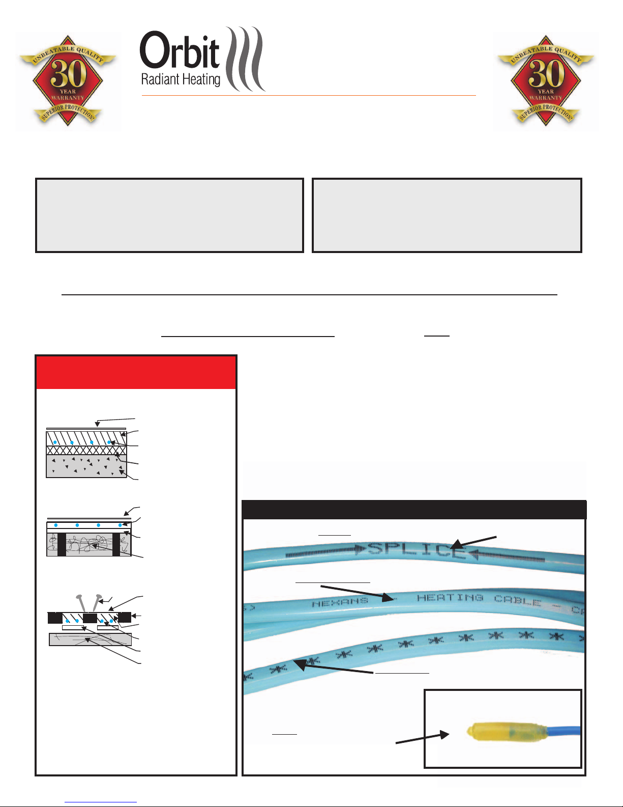
Typical Cable Installations
SLAB CONSTRUCTION
***FINISHED FLOORING
REINFORCED CONCRETE
**HEATING CABLE, IN NEW SLAB
OR ON TOP OF EXISTING SLAB.
MAXIMUM 2’’ FROM SURFACE.
GROUND RATED INSULATION
(OPTIONAL)
CRUSHED ROCK OR STONE
FRAME CONSTRUCTION
***FINISHED FLOORING
**HEATING CABLE
MIN. 5/8”
(* ) MASONRY MASS
SUB-FLOOR PLANKING
INSULATION
(OPTIONAL, RECOMMENDED)
Length
= 193 Ft. 193
The TXLP/2R Series Cable box sets are pre-engineered units available
for both 120 and 230 volt applications. Each cable has a specific length,
wattage, and ohms resistance reading. It is important that you supply
the TXLP/2R Heating Cable with the voltage it is designed and tagged
for. The heating cables are factory designed under precise specifications
and cannot be altered for any reason and are not interchangeable with
other cable.
CABLE
MUST
IT IS VERY IMPORTANT TO NEVER CUT THE HEATING
as this will damage the cable and void the warranty. Both splices
be buried in the masonry. These are the points where the cable is
attached to the cold lead, and on the opposite end where the heating
cable ends with the bulb. Note the thickness of the bulb when pouring
your flooring material to embed the cable. Only the cold leads can be out
of the masonry or concrete and run into the conduit.
*Identifying the Nexans TXLP Manufactured Heating Cable*
Cold lead “ ”, marked about 7’ from the start of cable.Splice
HARDWOOD FLOORING
NAILS
* Masonry Mass refers to any dry pack, self leveling
product, light weight bedding mortar, and all mortar
based aggregates.
** To secure the cable use either hot melt glue,
cable clips, or 3/8’’ crown staples. Or put down wire
mesh and secure with wire ties or duct tape.
*** Finished flooring refers to tile, marble, or radiant
compliant carpet, hardwood, and laminates.
HARDWOOD FLOORS, ONE
COVERING, MINIMAL THICKNESS
SLEEPERS
*MIN. 5/8" MASONRY MASS
(ASSURE NO AIR GAPS)
HEATING CABLE
INSULATION
SUB-FLOOR
(SLAB OR PLYWOOD)
(OPTIONAL)
Actual “ ” located between the splice and bulb.Heating Cable
‘’ ’’ identified by asterisks,
Cold Lead
located at the beginning of the cable.
‘‘ ’’ located on the end of
Bulb
the heating cable.
TESTING PROCEDURE (Tests Should Be Performed By A Licensed Electrician ONLY)
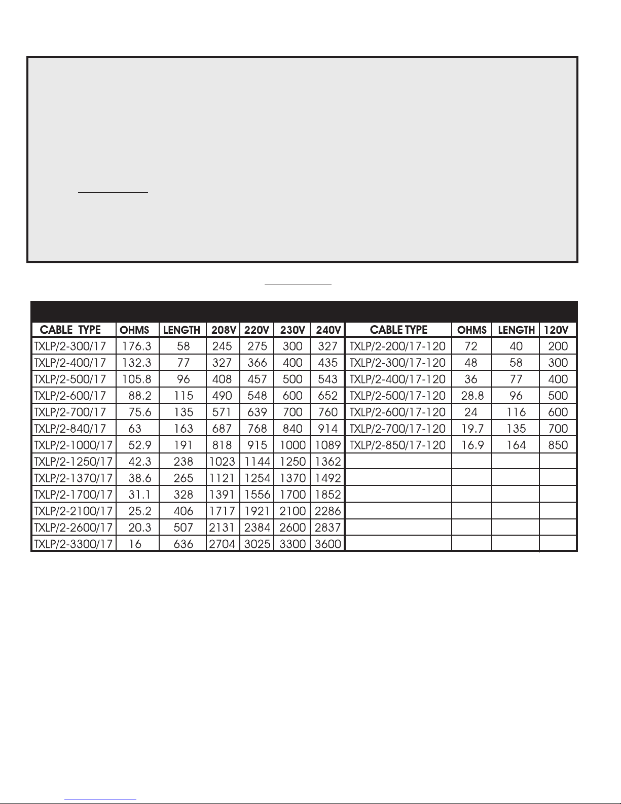
1. Verify that the cable you ordered is the one that you received.
2. Find your model number in Table 1 (Below) and record the Ohms for later use.
3. Visually inspect the heating cable before installation to locate obvious flaws or breaks.
4. With a digital OHM meter, first check resistance between the center conductor and the ground wire
(twisted copper). Reading should be OL or infinity.
5. Again use a digital OHM meter in order to verify proper Ohm resistance. Place one of the meter’s leads on
each of the cable’s conductors. The reading should be 10% (plus or minus) of the value in step 2.
6. With a megger, perform a leak test on the cable. (If a megger is not available, step 5 will have to suffice).
Place the positive (red) lead on one of the center conductors and the negative (black) lead on the ground
wire (twisted copper). The reading should be OL or infinity.
7. It is that a photo be taken of the floor after the cable is installed and before the final floorvery important
covering is laid. This will serve as a record of location and direction of cable runs. This can be used as
reference for future work to the area to avoid damaging the buried cables.
8. It is a good idea to keep the meter attached to the conductors during the pouring of the floor to note
any sudden change in the recorded value. If this occurs, STOP the installation to determine the cause.
9. Afterthecableisinstalledrepeatsteps4&5forwarranty registration purposes.
TABLE 1
Nexans TXLP/2 Cable Wattage Output Ratings At Different Voltages
GENERAL INSTALLATION GUIDELINES
Electrical Code and Safety: All heating cable installations shall be installed according to the National
Electric Code (NEC) Article 424 for space heating.
regulations of all authorities having jurisdiction.) Caution:
personnel, who are familiar with the construction, operation, and installation.
Before You Start:
Field measure the area for which the cable is designed to cover. Verify the area for the project is the same as the area
originally designed. If the area has changed (larger or smaller), please call the factory to assure that the cable will be
effective and operate in a safe manner. If you have any questions, it is important to contact our Tech Support
Department. Any changes in the pre-determined design area can seriously affect the performance of the system.
Do not exceed 15 Watts per square foot indoor in residential applications, or 33.5 Watts per square foot indoor for
commercial or industrial applications with any of the above cables.
(In addition, the installation shall be in accordance with the
This equipment shall only be installed by qualified
 Loading...