

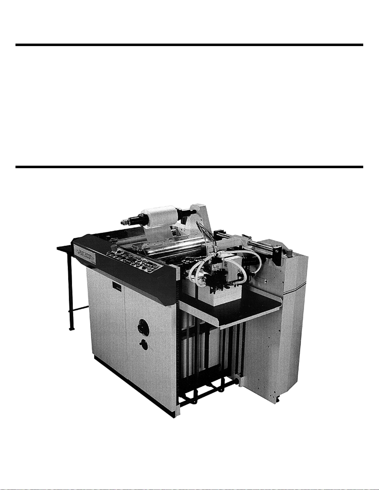
ORBIT ™ 2000 OPERATION &
MAINTENANCE MANUAL
© January 2001 GBC Films Group
Do not duplicate without written permission.
GBC Pro - T ech
4151 Anderson Road
DeForest, WI 53532
Revision : Ph: ( 608 ) 246 - 8844
Part number : 930 - 051
Fx: ( 608 ) 246 - 8645

Read me fileOrbit™ 2000 Operation and Maintenance Manual
Read Me File . . . . . . . . .
The information in this publication is provided for reference and is believed to be accurate and complete. GBC Films Group is not liable for errors in this publication or for incidental
or consequential damage in connection with the furnishing or use of the information in this
publication, including, but not limited to, any implied warranty of fitness or merchantability for
any particular use.
GBC Films Group reserves the right to make changes to this publication and to the
products described in it without notice. All specifications and information concerning products
are subject to change without notice.
Reference in this publication to information or products protected by copyright or patent
does not convey any license under the rights of GBC Films Group or others. GBC Films
Group assumes no liability arising from infringements of patents or any other rights of third
parties.
This publication is copyrighted © 2000 by GBC Films Group. All rights reserved. The
information contained in this publication is proprietary and may not be reproduced, stored,
transmitted, or transferred, in whole or in part, in any form without the prior and express written
permission of GBC Films Group.
The following information will explain how to move around within the electronic version
of this publication. The hand will change to a pointer finger identifying hyperlinked areas. When
moving from page to page, use
PAGE, use
from view to view, use
VIEW.
Should you find an error within this publication or would like to make a suggestion,
please utilize the fax correspondence sheet following this read me file and fax it to the number
provided. Your comments and help will ensure up to date information. Thank you.
to go back one PAGE and use to advance one PAGE. When moving
to return to a previous VIEW and use to advance to the next
to return to the first PAGE, use to advance to the last
© GBC Films Group January 2001

Read me file Orbit™ 2000 Operation and Maintenance Manual
This page intentionally left blank.
© GBC Films Group January 2001

Fax Correspondence
Fax number : ( 608 ) 246 - 8645 Date :
To : Sean Flood at GBC Pro-Tech
4151 Anderson Road
DeForest, WI 53532
From :
Company :
Address :
Phone number : ( ) Fax number : ( )
Read me fileOrbit™ 2000 Operation and Maintenance Manual
Re : Orbit™ 2000 Operations and Maintenance Manual ( 930051 )
Section #: Page #:
Correction (s):
Additional comments:
© GBC Films Group January 2001

Read me file Orbit™ 2000 Operation and Maintenance Manual
This page intentionally left blank.
© GBC Films Group January 2001

Section 1: Safety
1.1 Safety - Complete equipment......................................................................1 - 1
1.2 Safety - Rules for loading paper .................................................................1 - 4
1.3 Safety - Rules for handling the feeding head ..............................................1 - 5
1.4 Safety - Rules for setting up the rollers and the hinged stops .....................1 - 7
T able of ContentsOrbit™ 2000 Operation and Maintenance Manual
Table of Contents
1.5 Safety - Rules for set-up of the adjustable guide plates ..............................1 - 9
1.6 Safety - Rules for the chrome and pressure rollers ..................................1 - 10
1.7 Safety - Rules for the snap roller area ......................................................1 - 14
1.8 Safety - Rules for the use of the twin knife ...............................................1 - 17
1.9 Safety - Rules for the position adjustment of the decurling bar ................1 - 19
1.10 Safety - Rules for electrical installation .................................................1 - 20
1.11 Safety - Rules for machine cleaning .......................................................1 - 22
1.12 Safety - Rules for machine maintenance and adjustments .....................1 - 24
1.13 Safety - Rules for the feeder table ..........................................................1 - 26
© GBC Films Group January 2001
Page I

T able of Contents Orbit™ 2000 Operation and Maintenance Manual
1.14 Safety - Rules for the central drive maintenance ....................................1 - 27
1.15 Safety - Rules for snapping assembly/ chain/ belt drive maintnenance ..1 - 28
1.16 Safety - Rules for maintenance/ replacement of the twin knife ..............1 - 29
Section 2: Warranty
2.1 Terms and conditions .................................................................................2 - 1
2.2 Limited period of warranty ........................................................................2 - 2
2.3 Limited warranty conditions ......................................................................2 - 2
Section 3: Specifications
3.0 Specific dimensions and weight of the equipment illustration ...................3 - 1
Page II
3.1 Dimensions and weight of the equipment ....................................................3 -1
3.2 Shipping crate dimensions ..........................................................................3 - 2
3.3 Basic technical data ...................................................................................3 - 2
© GBC Films Group January 2001

Section 4: Installation
4.0 Installation precautions ..............................................................................4 - 1
4.1 Pre-installation check list ...........................................................................4 - 2
4.2 Suggested floor layout ................................................................................4 - 4
4.3 Shipping damage inspection .......................................................................4 - 5
4.4 Transporting of the machine ......................................................................4 - 6
T able of ContentsOrbit™ 2000 Operation and Maintenance Manual
4.5 Electrical installation .................................................................................4 - 7
4.6 Becker T4.25 DSK compressor installation ..............................................4 - 8
4.7 Initial inspection .........................................................................................4 - 9
Section 5: Operations
5.0 Operations ..................................................................................................5 - 1
5.1 General information ...................................................................................5 - 2
5.1.1 Main and secondary operator position ..........................................5 - 2
© GBC Films Group January 2001
Page III

T able of Contents Orbit™ 2000 Operation and Maintenance Manual
5.1.2 The control panel ...........................................................................5 - 3
Original overlay illustration ..........................................................5 - 4
New overlay illustration ................................................................5 - 5
5.2 Feeder section ............................................................................................5 - 6
5.2.1 Sheet stacking ................................................................................5 - 7
5.2.2 Feeder table positioning ................................................................5 - 9
5.2.3 The feeding head ..........................................................................5 - 10
5.2.4 First Gate ......................................................................................5 - 15
5.2.5 Feed roller assembly ....................................................................5 - 16
5.2.6 Second gate ...................................................................................5 - 21
5.2.7 Adjustable guide plates ................................................................5 - 22
5.3 Lamination section ....................................................................................5 - 23
Page IV
5.3.1 Film roll positioning .....................................................................5 - 23
5.3.2 Heating ...........................................................................................5 - 27
© GBC Films Group January 2001

T able of ContentsOrbit™ 2000 Operation and Maintenance Manual
5.3.3 Laminating rollers .........................................................................5 - 29
5.3.4 Spreader roller ( option ) .............................................................5 - 32
5.4 Separator Section ....................................................................................5 - 33
5.4.1 The decurling bar .........................................................................5 - 33
5.4.2 Pull rollers ....................................................................................5 - 37
5.4.3 Twin knife .....................................................................................5 - 40
5.4.4 Snapping assembly .......................................................................5 - 42
5.4.5 Stacking table ...............................................................................5 - 45
Section 6: Applications
6.1 Recommended film types ............................................................................6 - 1
6.2 General threading procedure .....................................................................6 - 2
6.3 Film threading diagram ..............................................................................6 - 5
© GBC Films Group January 2001
Page V

T able of Contents Orbit™ 2000 Operation and Maintenance Manual
Section 7: Troubleshooting
7.1 Lamination troubleshooting ......................................................................7 - 2
7.2 Wave pattern troubleshooting ...................................................................7 - 4
7.3 Feeder troubleshooting ..............................................................................7 - 9
7.4 Misfed sheets troubleshooting ..................................................................7 - 10
7.5 Web troubleshooting ..................................................................................7 - 11
7.6 Machine troubleshooting ...........................................................................7 - 12
Section 8: Maintenance
8.1 Maintenance schedule ...............................................................................8 - 2
8.2 Operators Maintenance .............................................................................8 - 5
8.2.1 Safety - Rules for machine cleaning ...............................................8 - 5
Page VI
8.2.2 Safety - Rules for maintenance/ replacement of the twin knife ......8 - 7
8.2.3 Feed table chain tensioning ...........................................................8 - 9
© GBC Films Group January 2001

1.0 Safety regulations
1.1 Safety - Complete equipment
ATTENTION
SafetyOrbit™ 2000 Operation and Maintenance Manual
1/
2/
Do not operate this equipment unless you have read and understand this
operator manual and have been fully trained in its operation by a
qualified GBC service technician.
ATTENTION
The operator may use the Orbit 2000 only for the lamination of paper sheets.
The equipment may not be used for any other type of work. The type of paper
and film must comply with conditions of Section 2 of the Technical Specifications.
The equipment is provided with means to control lamination functions. The
controls as set up by the factory may not be modified or altered.
3/
Do not operate , adjust, service or repair the Orbit 2000 if you are under the
influence of alcohol, drugs, or medication.
4/
Do not operate the Orbit 2000 if you are ill or tired.
© GBC Films Group January 2001
ATTENTION
ATTENTION
Page 1 - 1
Safety Orbit™ 2000 Operation and Maintenance Manual
ATTENTION
5/
6/
All safety covers must be in place during operation. The equipment must not be started
and used, if all covers are not in place, and safety switches are not operational.
ATTENTION
Test all three interlocked safety g ua rd s each d ay ( the ch ro m e roller gu ard ,
snap roller guard and the guard under the laminating and snap ARGA s ) and
the two em ergen cy stop sw itches ( one on the co ntrol p an el and on e on th e
drive side of th e feeder ) and the p ile up safety switch ( on the feeder ta b le
guide ra ils )to ensure tha t they fu nction p rop erly.
7/
8/
ATTENTION
Exercise extreme caution when working with sheets to avoid paper cuts.
ATTENTION
Never clean any rollers while the equipment is running. If needed, turn the rollers for
cleaning or testing by using the slow forward or slow reverse push buttons.
ATTENTION
9/
Page 1 - 2
When using the slow forward and slow reverse push buttons, push and
release the buttons and wait for the machine to stop before cleaning
the exposed area of the rollers.
© GBC Films Group January 2001
ATTENTION
SafetyOrbit™ 2000 Operation and Maintenance Manual
10/
11/
Never p erfo rm ad ju stm en ts w hile the m a ch ine is run n ing. T h e m ach in e m u st first be
stopped , ad justed a nd th en restarted. ( Ex cep t When A d justing Lap For S h eet Size ! )
ATTENTION
Excercise caution when working around the feeder table, control panel and
stacking tray to avoid bumping you head.
ATTENTION
12/
13/
14/
The equipment must be fixed/ positioned on a firm and even floor. The
working station of the operator must be at the same level.
ATTENTION
The operator shall provide adequate lighting suitable for the given task.
ELECTRICAL
SHOCK
Do not remove or modify any guards, covers or enclosures. Contact with any
moving parts or/ and electrical voltage can result in injury or death!
© GBC Films Group January 2001
Page 1 - 3
Safety Orbit™ 2000 Operation and Maintenance Manual
1.2 Safety - Rules for loading paper
The normal function of the equipment is to insert paper and laminate it. For a safe loading of paper
it is necessary to follow these safety rules:
ATTENTION
1/
2/
3/
Do not attempt to load paper while the machine is running. Your fingers
couldbe hurt during the automatic insertion of paper.
WARNING
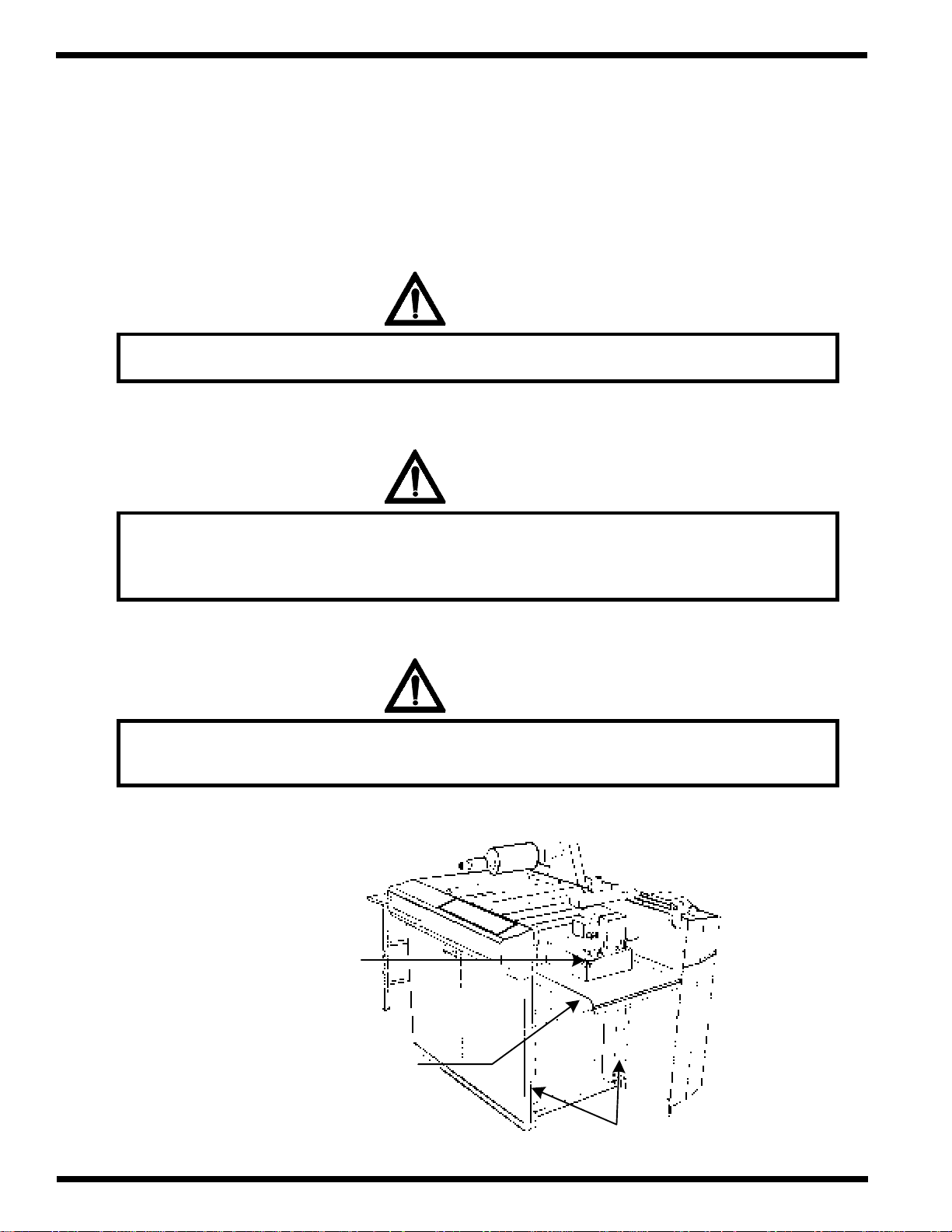
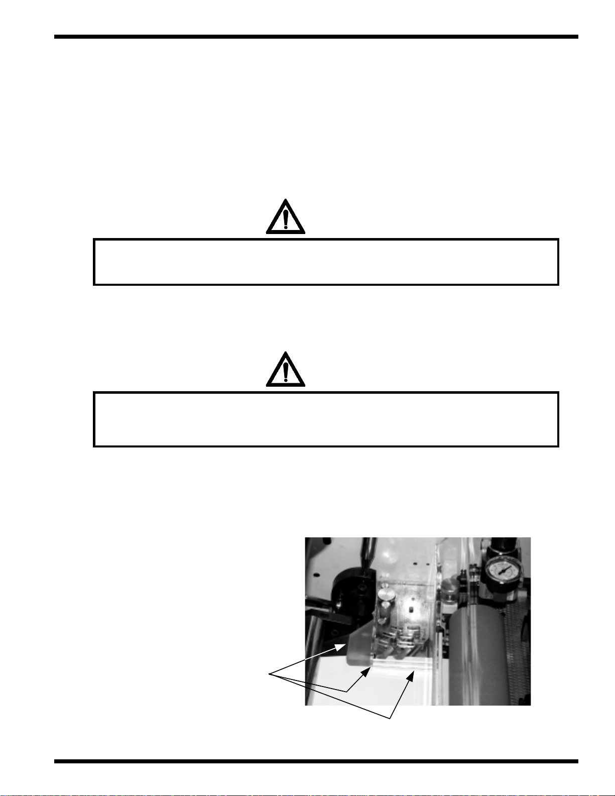
Ensure the feeder stack/ pile is in the bottom position before loading paper. To move
into that position, press the Pile/ Stack down push button.
CAUTION: Avoid bumping your head on the feeder when loading paper.
WARNING
Do not touch the stack/ pile, table or chains with your fingers or other body
parts when the table is moving or the laminator is running.
Page 1 - 4
Feeder Stack/ Pile
Feeder Table
Chains
© GBC Films Group January 2001
SafetyOrbit™ 2000 Operation and Maintenance Manual
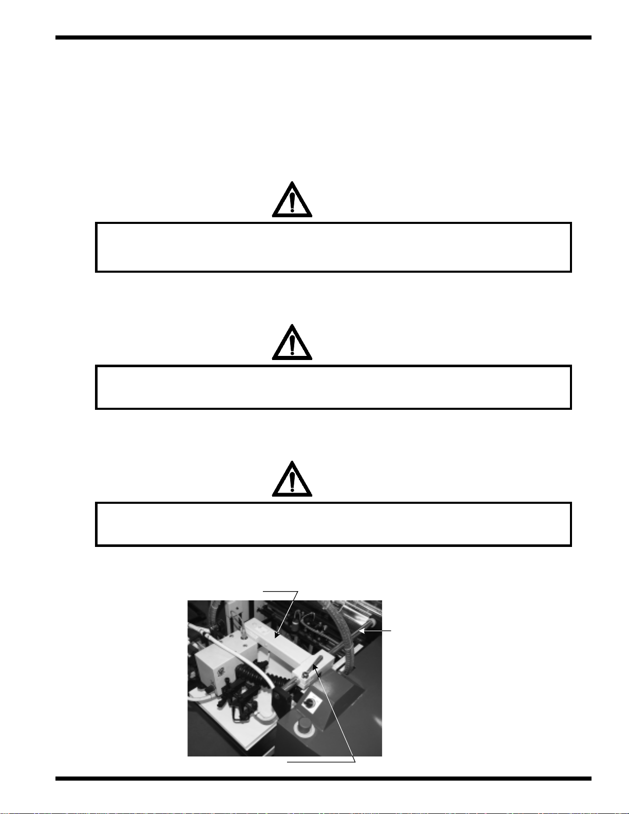
1.3 Safety - Rules for handling the feeding head
The feeding head grabs the paper sheet and inserts it into the pull rollers. When changing paper
size, the position of the feeding head must also be changed. For safe adjustments, the following safety rules
apply:
WARNING
1/
2/
3/
Do not touch the feeder head while the machine is running. The moving
suction cups may hurt your hands or fingers.
ATTENTION
Do not adjust the feeding head while the machine is running with the
exception of the control buttons described in Section 5.0
ATTENTION
To move the head, loosen the clamp on the locating bar, then slide the head
by grabbing the upper handle bar and gently pull or push.
Handle bar
Clamp
© GBC Films Group January 2001
Locating bar
Page 1 - 5
Safety Orbit™ 2000 Operation and Maintenance Manual
ATTENTION
4/
Do n ot p lace an y o bjects on the u p p er su rface of th e feed ing h ead or f eeder tab le.
ATTENTION
5/
6/
Do not remove covers, fixed cover of the feeding head
and/ or the protective rubber cover.
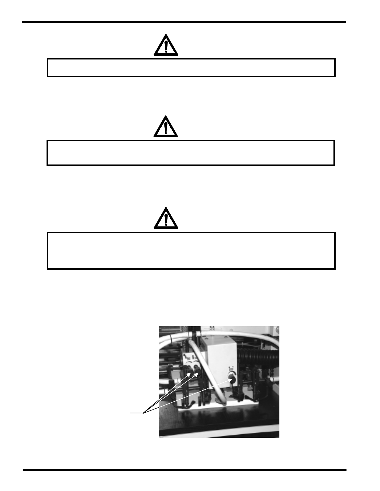
ATTENTION
Op erate th e turn ing k n ob s carefu lly an d w ith on ly on e h an d w h ile the
machine is running. Only trained operators may use the machine. Do not wear
ties, loose fit clothing or dangling jew elry while operating the machine.
Page 1 - 6
Turning
knobs
© GBC Films Group January 2001
SafetyOrbit™ 2000 Operation and Maintenance Manual
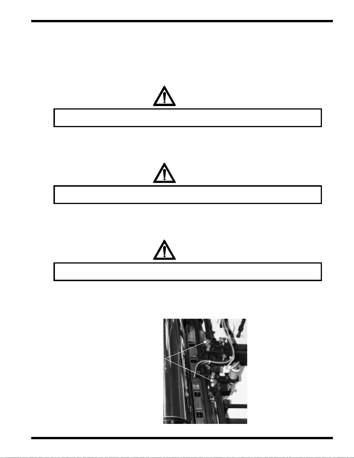
1.4 Safety - Rules for setting up the rollers and the hinged
stops
ATTENTION
1/
2/
3/
Do not touch the rollers or hinged stops while the machine is running.
WARNING
WARNING: The chrome roller may be hot. Contact will result in severe burns!
ATTENTION
The insertion or removal of any weights is permissable only when the machine is idle.
Counter weights
© GBC Films Group January 2001
Page 1 - 7
Safety Orbit™ 2000 Operation and Maintenance Manual
WARNING
4/
5/
Caution: Excercise extreme caution when adjusting the rollers
to avoid pinching by the loading roller.
ATTENTION
Ha nd le the ro llers only w h en the P lexi-glass cover of th e ch rom e ro ller is closed.
ATTENTION
6/
7/
Keep fingers, hands and clothing clear away from the rollers
while the machine is in operation.
WARNING
WARNING: Do not be startled by the pressure roller dropping
approximately two minutes after the laminator has been stopped.
Page 1 - 8
© GBC Films Group January 2001
SafetyOrbit™ 2000 Operation and Maintenance Manual
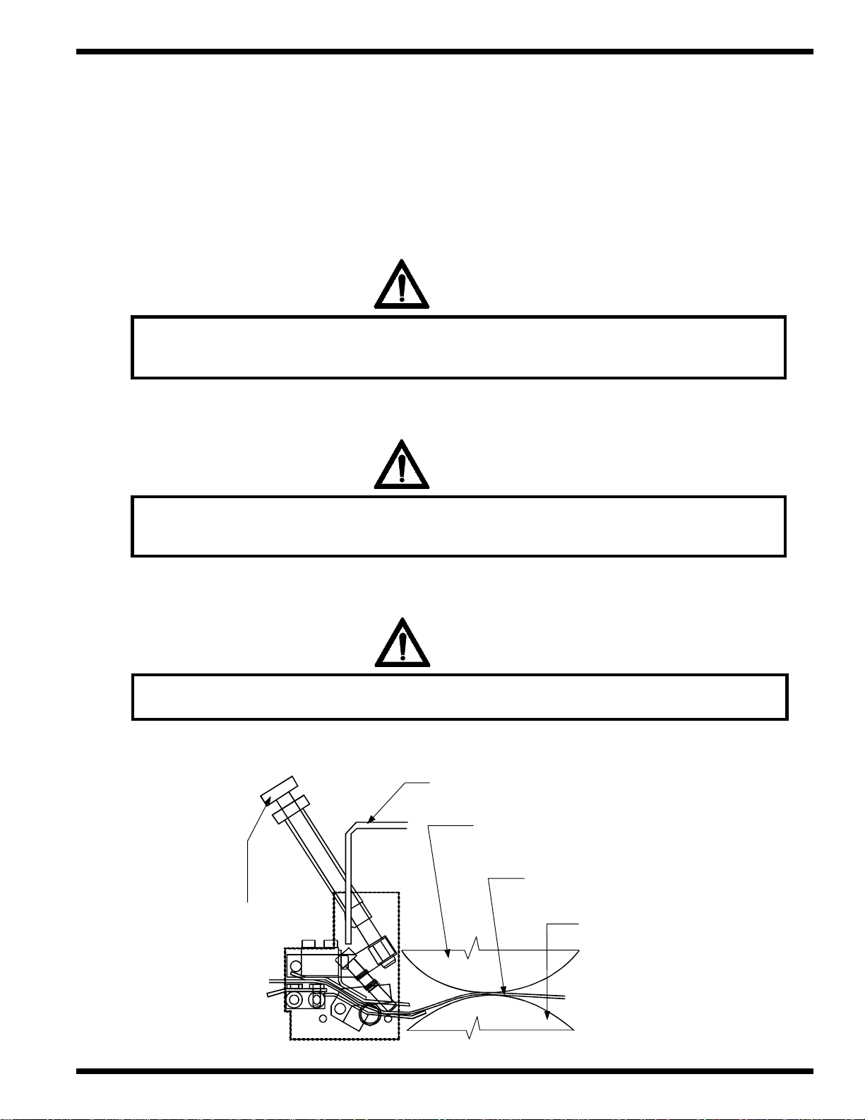
1.5 Safety - Rules for setup of the adjustable guide plates
The guiding plates form paper before it enters into the chrome roller . Their position must be adjusted
for different paper weights. For a safe adjustment of plates follow these safety rules:
ATTENTION
1/
2/
3/
The plate's position may be adjusted while the equipment is running by using
the set-up screw. This may only be performed by a trained operator.
WARNING
CAUTION: Do not wear ties, loose fit clothing or dangling jewelry. These items
can get caught by the hinged stops or the feed rollers.
ATTENTION
Th e ch rom e ro ller gua rd must be in the fu lly closed p osition.
Se t-u p s c re w
© GBC Films Group January 2001
Chro m e ro ller guard
Chro m e ro ller
Pa p e r & f ilm s to c k
Pressure roller
Page 1 - 9
Safety Orbit™ 2000 Operation and Maintenance Manual
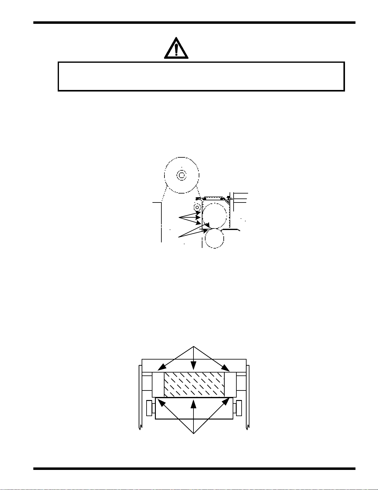
1.6 Safety - Rules for the chrome and pressure rollers
The working temperature of the chrome roller is 120 to 135 deg C. Because of the machine function
it is not possible to cover the area around the chrome and pr essur e rollers completely. Near the contact
area of the rollers, there is a very dangerous zone. Because of that and the high temperature, the following
safety rules must be complied with:
WARNING
1/
2/
WARNING: The chrome roller may be hot. Contact will result in severe burns!
WARNING
WARNING: Keep fingers, hands and other body parts away from the rollers.
WARNING
3/
4/
Page 1 - 10
CAUTION: Never clean the surface of the rollers while the machine is running.
Use the Slow FWD and Slow Reverse to change the exposed area for cleaning.
WARNING
CAUTION: Do not wear ties, loose fit clothing or dangling jewelry. These items
can get caught the rollers while working around or loading film.
© GBC Films Group January 2001
WARNING
SafetyOrbit™ 2000 Operation and Maintenance Manual
5/
6/
CAUTION: Do not use any tools for cleaning or removing remnants of films
from the rollers while the machine is in operation.
ELECTRICAL
SHOCK
Do not remove or modify any guards, covers or enclosures. Contact with any
moving parts or/ and electrical voltage can result in injury or death!
WARNING
7/
8/
CAUTION: Do not cover the chrome roller guard ventilation holes.
ATTENTION
When cleaning, follow the rules for Safety - Rules for cleaning in Section 3.10
WARNING
9/
WARNING: Keep hands and fingers away from the pressure/ chrome roller when
using Pressure Roll Up/ Close and Down/ Open push buttons.
© GBC Films Group January 2001
Page 1 - 11
Safety Orbit™ 2000 Operation and Maintenance Manual
WARNING
10/
11/
WARNING: Depress the laminator Stop button before attempting to
perform any web up procedure on the laminator.
ATTENTION
Alw ay s ensu re the ad h esive is facing away from the ch rom e ro ller wh en load ing film.
WARNING
12/
13/
CAUTION: Open the plastic chrome roller guard fully to prevent to
accidental closing onto your hands and fingers.
WARNING
WARNING: Hot surface. Ensure the chrome roller is below 122
O
F ( 50 OC )
before servicing or adjusting. Check the temperature on the temperature
control display or by using an external temperature sensor or wait
60 minutes from the time the machine has been turned off.
Page 1 - 12
© GBC Films Group January 2001
WARNING
SafetyOrbit™ 2000 Operation and Maintenance Manual
14/
WARNING: Avoid making contact with any of the hot surface areas. Avoid all
pin ch points an d cr u sh h a za rd a r ea s a s illu str a ted b e lo w.
Side view
a - DANGER: High temperature
roller surface area.
b - DANGER: Pinch/ Crush
point area.
a
b
© GBC Films Group January 2001
Rear view
WARNING: Hot surface area
WARNING: Crush hazard area
Page 1 - 13
Safety Orbit™ 2000 Operation and Maintenance Manual
1.7 Safety - Rules for the snap roller area
It is not possible to cover the entire zone around the snapping roller because of the operation of the
machine. It is therefore necessary to observe the following safety rules:
WARNING
1/
2/
CAUTION: Do not adjust the regulating screws of the sn a pp ing roller w h ile the
lamina tor is in opera tion. D u ring op era tion the reg ulating screw h an d le is mov ing a n d
your fin gers may be cru shed b etw een the reg u lating screws and the P lexi-Glass co ver.
WARNING
CAUTION: Do not place your fingers or any other part of your body near the contact
point between the upper and lower snap rollers.
ATTEN TION
3/
4/
Page 1 - 14
Du ring o peration, the plastic cover mu st rem ain in the fu lly closed position.
WARNING
CAUTION: Open the plastic snap roller guard fully to prevent accidental
closing onto your hands or fingers.
© GBC Films Group January 2001
WARNING
SafetyOrbit™ 2000 Operation and Maintenance Manual
5/
CAUTION: Do not place any objects on the plastic snap roller guard.
6/
Do not remove or modify any guards, covers or enclosures. Contact with any
moving parts or/ and electrical voltage can result in injury or death!
The snap roller side view
ELECTRICAL
SHOCK
CAUTION: Keep fingers clear during
machine operation
Adjusting regulating screws
W ARNING: Pinch hazard area
DANGER: Crush point by
Regulating Screws
Top
Bottom
© GBC Films Group January 2001
Page 1 - 15
Safety Orbit™ 2000 Operation and Maintenance Manual
Regulating screw view from the stacking table
CAUTION: Finger Crush hazard area
Rear view of the Snap Roller Guard Cover
Page 1 - 16
© GBC Films Group January 2001
1.8 Safety - Rules for the use of the twin knife
The cutting knives are covered by plastic guards from the top and side. Because of the sharpness
and speed with which the knives move it is necessary to observe the following safety rules:
WARNING
SafetyOrbit™ 2000 Operation and Maintenance Manual
1/
2/
CAUTION: Do not place your fingers or any other part of your body near
the plastic guard while the machine is running.
WARNING
WARNING: Do not place your fingers or objects under the plastic guard,
unless the equipment is disconnected from the power supply and the
emergency stop switch is depressed.
WARNING: Sharp knife can cut you!
Remove power and depress
emergency stop switch before
woking in this vicinity.
© GBC Films Group January 2001
Page 1 - 17
Safety Orbit™ 2000 Operation and Maintenance Manual
WARNING
3/
4/
WARNING: For safe knife adjustment, use a 4 mm allen wrench only. The allen
wrench can be inserted through the oval shaped openings in the upper
section of the plastic guard of the twin knife.
WARNING
WARNING: Disconnect power to the equipment before performing any task in the
vicinity of the twin knife requiring the removal of the cover
ATTEN TION
5/
6/
7/
Do not operate the laminator unless the plastic guard is in place above the twin knife.
WARNING
CAUTION: Do not place any objects on the plastic knife guard.
ELECTRICAL
SHOCK
Do not remove or modify any guards, covers or enclosures. Contact with any
moving parts or/ and electrical voltage can result in injury or death!
Page 1 - 18
© GBC Films Group January 2001
SafetyOrbit™ 2000 Operation and Maintenance Manual
1.9 Safety - Rules for the position adjustment of the decurling bar
During lamination internal stress develops between paper and the chrome roller. The decurling
bar straightens the sheets before they exit the lamination section. During adjustment of the bar , the
following safety rules must be observed:
WARNING
1/
2/
CAUTION: Exercise caution while loosening the decurling bar handle.
The securing screw and the edge of the groove on the regulating
wheel may collide during sudden loosening.
WARNING
CAUTION: Exercise caution while adjusting the control lever position.
During sudden change in the position of the control lever, the set-up
lever of the decurling bar may be hit.
WARNING
3/
4/
CAUTION: Do not place your fingers near the groove on the regulating
wheel while changing the position of the decurling bar.
CAUTION: Due to heat eminating from the chrome roller and pressure
roller area, avoid contact with the decurling bar.
© GBC Films Group January 2001
WARNING
Page 1 - 19
Safety Orbit™ 2000 Operation and Maintenance Manual
1.10 Safety - Rules for electrical installation
WARNING
1/
CAUTION: Repairs, adjustments and/ or maintenance may be performed
by a qualified technician ( excludes any operator maintenance and operator
adjustments ). The word "qualified" is decribed below.
Qualified
• Any engineer that has experience with electrical and mechanical design of lamination equipment.
The engineers should be fully aware of all aspects of safety with regards to lamination equipment.
• Any commissioning or service engineer must be of competent nature, trained and qualified to GBC
Pro-T ech standards to fulfill that job. This person will have completed and passed the full service training
course from GBC Pro-T ech.
• Any GBC T echnician, GBC Specialist, and / or GBC Pro-Tech T echnician that has been through
the GBC Pro-T ech service training course.
2/
Page 1 - 20
WARNING: Operator maintenance and operator adjustments may be performed
only by person(s) trained in all aspects of the equipment.
WARNING
© GBC Films Group January 2001
WARNING
SafetyOrbit™ 2000 Operation and Maintenance Manual
3/
4/
5/
WARNING: At no time should you attempt to overide/ by pass and safety shield,
safety switches or safety device located on this equipment.
ELECTRICAL
SHOCK
WARNING: Do not modify any part of the circuitry at any time or for any reason!
WARNING
WARNING: All guards and covers must be returned to their original position after any
repairs, adjustments and/ or maintenance has been completed.
6/
7/
WARNING: At least 1 ft. ( 1 meter ) of free space is required in front of the machine to
allow for safe access for work on the machine electrical system.
Do not remove or modify any guards, covers or enclosures. Contact with any
moving parts or/ and electrical voltage can result in injury or death!
© GBC Films Group January 2001
WARNING
ELECTRICAL
SHOCK
Page 1 - 21

Safety Orbit™ 2000 Operation and Maintenance Manual
1.11 Safety - Rules for machine cleaning
WARNING
1/
2/
WARNING: Do not clean any part of the machine while the laminator is in operation.
WARNING
CAUTION: Never clean the surface of the rollers while the machine is running.
Use the Slow FWD and Slow Reverse to change the exposed area for cleaning.
Use the sequence described below.
a/ Press and hold the Inch/ Slow FWD or Reverse/ Slow Reverse push button.
b/ Release the perspective push button and wait for the machine to stop.
c/ Clean the exposed area of the rollers.
d/ Repeat as necessary.
Page 1 - 22
WARNING
WARNING: The chrome roller is hot. Contact will result in severe burns!
© GBC Films Group January 2001

WARNING
SafetyOrbit™ 2000 Operation and Maintenance Manual
3/
4/
5/
WARNING: Hot surface. Exercise extreme caution when cleaning the chrome roller.
Surface temperatures may be upwards of 248
ATTENTION
Always use cotton or Nomex gloves when cleaning the chrome roller.
CAUTION: Do not use aggressive solvents that could cause damage to
the rubber rollers. Use only Mineral Spirits.
TM
WARNING
O
F to 275 OF ( 120 - 135 OC ).
6/
7/
WARNING: Crush hazard exists near any rollers. Do not press Pressure Up/ Pressure
Roll Close switch when your hands or fingers are near the pressure roller arms.
Do not remove or modify any guards, covers or enclosures. Contact with any
moving parts or/ and electrical voltage can result in injury or death!
© GBC Films Group January 2001
WARNING
ELECTRICAL
SHOCK
Page 1 - 23

Safety Orbit™ 2000 Operation and Maintenance Manual
1.12 Safety - Rules for machine maintenance and adjustments
WARNING
1/
2/
WARNING: Do not remove any covers or guards while the machine is in operation.
WARNING
WARNING: Do not start the machine with the guards or covers removed.
3/
4/
WARNING
WARNING: Shut off and lock the electric supply circuit breaker before performing
any operator maintenance or operator adjustments.
WARNING
WARNING: Hot surface! Ensure the chrome roller temperature is below
122 OF ( 50 OC ) before servicing or adjusting.
Page 1 - 24
© GBC Films Group January 2001

5/
SafetyOrbit™ 2000 Operation and Maintenance Manual
WARNING
WARNING: Check the temperature on the temperature control display if power
is "ON" or by using an external temperature sensor or wait 60 minutes from
the time the machine has been turned off before performing any
operator maintenance, operator adjustments or set-up.
WARNING
6/
7/
8/
CAUTION: Do not wear ties, loose fit clothing or dangling jewelry. These items
can get caught by moving parts while performing tasks.
WARNING
CAUTION: Always wear safety glasses when changing the springs.
Uncontrolled springs can damage your eyes.
WARNING
WARNING: Operator maintenance and operator adjustments may be performed
only by person(s) trained in all aspects of the equipment.
9/
Do not remove or modify any guards, covers or enclosures. Contact with any
moving parts or/ and electrical voltage can result in injury or death!
© GBC Films Group January 2001
ELECTRICAL
SHOCK
Page 1 - 25

Safety Orbit™ 2000 Operation and Maintenance Manual
1.13 Safety - Rules for the feeder table
During the automated run the feeder table moves upward in steps. When a new ream of paper is
loaded, the table must be moved down. T o ensure your safety , the following safety rules should be followed:
WARNING
1/
2/
WARNING: Operation of the feeder table may be performed only by
person(s) trained in all aspects of the equipment.
ATTEN TION
Use the Pile/ Stack Up or Pile/ Stack Down push buttons to move the feeder table.
3/
Page 1 - 26
ELECTRICAL
SHOCK
Do not remove or modify any guards, covers or enclosures. Contact with any
moving parts or/ and electrical voltage can result in injury or death!
© GBC Films Group January 2001

SafetyOrbit™ 2000 Operation and Maintenance Manual
1.14 Safety - Rules for the central drive maintenance
The main motor drives the feeding head, the feeding roller , and the chrome roller. It is located on the
opposite side from the operator, and protected by a fixed cover. For safe work, the following safety rules
should be followed:
1/
2/
WARNING
WARNING: Shut off the compressed air intake before setting up the
second hinged end-stops and pressure rollers.
WARNING
WARNING: Only person(s) trained in all aspects of the equipment may
operate the central drive.
ELECTRICAL
SHOCK
3/
Do not remove or modify any guards, covers or enclosures. Contact with any
moving parts or/ and electrical voltage can result in injury or death!
© GBC Films Group January 2001
Page 1 - 27

Safety Orbit™ 2000 Operation and Maintenance Manual
1.15 Safety - Rules for Snapping assembly/ chain/ belt drive maintenance
The chain and belt drives are protected by a fixed cover and is located on the opposite side from the
operator . For safe work, the following safety rules should be followed:
WARNING
1/
2/
WARNING: Turn power off at the main breaker before tentioning the chains or belts.
ATTEN TION
O p er a tor m a in te n ance for th e c h a in s a n d b elts ar e limited to lu b r ica tion an d
tentioning. All other work must be performed by a qualified technician.
3/
Page 1 - 28
ELECTRICAL
SHOCK
Do not modify any guards, covers or enclosures. Contact with any
moving parts or/ and electrical voltage can result in injury or death!
© GBC Films Group January 2001

SafetyOrbit™ 2000 Operation and Maintenance Manual
1.16 Safety - Rules for maintenance/ replacement of the twin knife
The twin knife is very sharp and extreme caution should be exercised when working in its vicinity .
For safe work, the following safety rules should be followed:
WARNING
1/
2/
3/
WARNING: Knife has sharp edges! Do not touch the sharp edges of the knives.
WARNING
WARNING: For safe knife adjustment, use a 4 mm allen wrench only. The allen
wrench can be inserted through the oval shaped openings in the upper
section of the plastic guard of the twin knife.
WARNING
WARNING: Do not place your fingers or objects under the plastic guard,
unless the equipment is disconnected from the power supply and the
emergency stop switch is depressed.
4/
© GBC Films Group January 2001
Do not remove or modify any guards, covers or enclosures. Contact with any
moving parts or/ and electrical voltage can result in injury or death!
ELECTRICAL
SHOCK
Page 1 - 29

Safety Orbit™ 2000 Operation and Maintenance Manual
This page intentionally left blank.
Page 1 - 30
© GBC Films Group January 2001

Orbit™ 2000 Operation and Maintenance Manual
Warranty
2.0 Warranty
GBC Films Group’s sole and exclusive liability and the customer’ s sole and exclusive remedy under
this warranty shall be, at GBC Films Group’s option, to r epair or replace any such defective part or product.
These remedies are only available if GBC Films Group’s examination of the product discloses to GBC
Films Group’s satisfaction that such defects actually exist and wer e not caused by misuse, neglect, attempt
to repair , unauthorized alteration or modification, incorrect line voltage, fir e, accident, flood or other hazards.
2.1 Terms and conditions
2.1.1 GBC Films Group warrants that the laminating machine ORBIT™ 2000, except as noted
below, is fr ee from defects in material and workmanship for a period of ( 3 ) three months from the date of
installation.
2.1.2 The warranty shall be limited to repairs, adjustments and/ or replacement as deemed
necessary by GBC Films Group.
2.1.3 THE WARRANTY MADE HEREIN IS IN LIEU OF ALL OTHER WARRANTIES,
EXPRESS OR IMPLIED, INCLUDING ANY WARRANTY OR MERCHANTABILITY OR FITNESS
FOR A P AR TICULAR PURPOSE. GBC FILMS GROUP WILL NOT BE LIABLE FOR PROPERTY
DAMAGE OR PERSONAL INJURY ( UNLESS PRIMARIL Y CAUSED BY ITS NEGLIGENCE ), LOSS
OF PROFIT OR OTHER INCIDENT AL OR CONSEQUENTIAL DAMAGES ARISING OUT OF THE
USE OR INABILITY TO USE THE EQUIPMENT .
© GBC Films Group January 2001
Page 2 - 1

Warranty Orbit™ 2000 Operation and Maintenance Manual
2.2 Limited period of warranty
Consumption replacement parts are warranted to be free from defects and workmanship for a period
of ( 60 ) sixty days from date of installation and include:
• Nip rollers, Snapping rollers and Pull rollers
• All rubber made rollers
• All belts
• Feeder suction cups
Warranty r epair or replacement does not extend the warranty beyond the initial ( 60 ) day period
from the date of installation.
2.3 Limited warranty conditions
The warranty becomes void in the event of mishandling, tampering, incorrect use of films not
compatible with our equipment or use contrary to the applicable instruction materials, shipping damage or
repair performed by other than a qualified service personnel authorized by GBC. Routine maintenance,
cleaning, adjustments, normal cosmetic and mechanical wear or deterioration due to extreme conditions
are not covered by this warranty .
Page 2 - 2 © GBC Films Group January 2001

Orbit™ 2000 Operation and Maintenance Manual
Warranty
2.3.1 Warranty is not applicable to the following conditions:
1/ Damage to the chrome laminating roller , rubberized feeding r ollers, pressure r ollers, pull rollers
and snapping rollers if caused by knives, razor blades or any other type of sharp tool.
2/ Damage to the chrome laminating roller , rubberized feeding r ollers, pressure r ollers, pull rollers
and snapping rollers if caused by:
– any object falling into the working area of the machine.
– cleaning the rollers using solutions or material that could harm the surface. Refer to Section 8
Maintenance under cleaning the rollers for suitable cleaners.
3/ Damage to the Plexi-Glass panels or air regulator glass caused:
– mechanically
– by using cleaners that would harm the Plexi-Glass covers
4/ Damage to the exterior finish caused:
– mechanically
– by using cleaning solvents that would harm the finish. Refer to Section 8 Maintenance under
cleaning the exterior for suitable cleaners.
5/ Damage to the feeding head by incompetent handling or adjusting.
6/ Damage to the machine caused by:
– moving
– installation performed by any person other than a qualified GBC service technician
– Operation of the equipment by person(s) not fully trained in all aspects of the machine.
© GBC Films Group January 2001
Page 2 - 3

Warranty Orbit™ 2000 Operation and Maintenance Manual
This page intentionally left blank.
Page 2 - 4 © GBC Films Group January 2001

SpecificationsOrbit™ 2000 Operation and Maintenance Manual
3.0 Specific dimensions and weight of the equipment
1956 mm
1325 mm
1010 mm
718 mm
1025 mm
1010 mm
1210 mm
3.1 DIMENSIONS AND WEIGHT OF THE EQUIPMENT
US VERSION EU VERSION
Machine dimensions 77" x 39.76" x 47.64" 1956 x 1010 x 1210 mm
(length x width x height) (length x width x height)
Base dimensions 3.3' x 6.4' 1.01 x 1.96 m
Floor area 21.3 ft
Weight of the Machine 1543 Ib 700 kg
2
1.98 m
© GBC Films Group January 2001
2
Page 3 - 1

Specifications
Orbit™ 2000 Operation and Maintenance Manual
3.2 SHIPPING CRATE DIMENSIONS AND WEIGHT
US VERSION EU VERSION
Dimensions of the crate with machine 59.1" x 47.3" x 56.7" 1500 x 1200 x 1440 mm
(length x width x height) (length x width x height)
W eight of the Machine with the crate 1676 lb 760 kg
3.3 BASIC TECHNICAL DATA
1. P APER SPECIFICATION
Max. paper size 14" x 20" 360 x 520 mm
Min. paper size 8" x 8" 200 x 200 mm
Smallest paper size 70 lb - 24 pt 115 - 350 g/m
2. FILM SPECIFICATIONS
T ypes of useable films Polypropylene, Polyester , Nylon film
Film gauge 1.0 - 1.7 mil. 1.0 - 1.7 mil.
Inside film roll diameter 21/4" - 3" 57 - 77 mm
Outside film roll diameter 7.4" 190 mm
Length of rolled film 1700 ft520 m
3. MACHINE PARAMETER
Speed 65 ft/min. 20 m/min.
Feeder pile height 25" 635 mm
US VERSION EU VERSION
2
4. ACOUSTIC NOISE DAT A
Equivalent noise level L AEG 75.3 dB (A) 75.3 dB (A)
Maximum noise level L Aeg (max) 79.8 dB (A) 79.8 dB (A)
Level of the acoustic output L W A 87.7 dB (A) 87.7 dB (A)
Page 3 - 2
© GBC Films Group January 2001

5. ELECTRICAL CIRCUIT
Power input 5 kV A +/- 10 % 5 kVA +/- 10 %
Basic voltage requirements 3 phase 230 V 60 Hz 3 phase 400 V 50
Nominal current 30 A 30 A
6. PNEUMATIC CIRCUIT
Pressure in the machine circuit 90 psi @ 4 CFM 0,6 MPa @ 113 l/min.
The feeder pneumatic circuit
- vacuum - 0.6 Bar - 0.6 Bar
- pressure +0.6 Bar +0.6 Bar
SpecificationsOrbit™ 2000 Operation and Maintenance Manual
US VERSION EU VERSION
with ground Hz with ground
7. MIN/ MAX 1ft./ min / 65 ft./ min .3 m/ min. / 20 m./ min
Slow Forward V ariable speed V ariable speed
Slow Reverse V ariable speed V ariable speed
© GBC Films Group January 2001
Page 3 - 3

Specifications
This page intentionally left blank.
Orbit™ 2000 Operation and Maintenance Manual
Page 3 - 4
© GBC Films Group January 2001

InstallationOrbit™ 2000 Operation and Maintenance Manual
4.0 Installation Precautions
WARNING
WARNING: To avoid injury to yourself or damage to the equipment, please
read and understand the instructions in this manual before you
attempt to install, operate or service the laminator!
1. The GBC Orbit™ 2000 System may be installed only by a qualified ( as defined below ) GBC employed technician.
2. Any moving or un-installing of the equipment may also, only be done by a qualified ( as defined below ) GBC
employed technician.
3. Once the machine is installed, all cables remaining on the floor from the electrical cabinet to the machine must be
covered, to avoid any accidents.
Qualified
• Any engineer that has experience with electrical and mechanical design of lamination equipment. The engineers
should be fully aware of all aspects of safety with regards to lamination equipment.
• Any commissioning or service engineer must be of competent nature, trained and qualified to GBC Pro-T ech
standards to fulfill that job. This person will have completed and passed the full service training course from GBC ProT ech.
• Any GBC T echnician, GBC Specialist, and / or GBC Pro-T ech T echnician that has been through the GBC
Pro-T ech service training course.
© GBC Films Group January 2001
Page 4 - 1

Installation
Orbit™ 2000 Operation and Maintenance Manual
4.1 Pre-installation checklist
The installation of the machine, the start-up of operation, and training must be provided by a qualified
GBC Films Group service technician, or another authorized organization.
Prior to the machine installation it is necessary to provide:
– an even floor of 2500 kg/ sq. meter minimal load factor ( 36.165 lb/ sq.ft ).
– a connection to air pressure of 0.6 Mpa @ 1 13L/ min. ( 90 PSI @ 4 CFM ) for the pneumatic
circuit.
– a fused dicconnect
– a connection of 3 phase with ground, 400/ 230VAC+/- 10 %, 50 Hz, 30 amps ( EU V ersion )
for the electrical circuit.
– a connection of 3 phase with ground 230VAC +/- 10 %, 60Hz, 30 amps ( US V ersion ) for
the electrical circuit.
Becker Compressor
The Becker compressor supplies air to the feeding assembly , and is connected by means of
a plug to the machine.
Machine position
The machine must be placed so that
Page 4 - 2
– space of at least 40 cm (1.3 ft) is available between the stacking table and the wall or any
other fixed object
– space of at least 80 cm (2.6 ft) is available on the drive side between the covers and the wall
or any other fixed object (another machine, etc.)
© GBC Films Group January 2001

InstallationOrbit™ 2000 Operation and Maintenance Manual
The Floor
The machine must be placed on a firm and reasonably even floor capable of supporting a
load of 2500 kg/ square meter ( 36165 lb/ sq.ft. ).
Note
The machine is also provided with a terminal to connect an additional conductor for the interconnection, since the value of leakage currents from noise suppression elements is higher than 3.5
mA AC. This terminal for the additional interconnection can be located on the bar between the side
plates, when the lower cover on the operator's side has been opened. The additional interconnecting
conductor is to be attached to this terminal.
ELECTRICAL
SHOCK
Only a qualified electrician should connect power to the laminator. You can be severely
shocked, electrocuted or cause a fire if power is improperly applied.
ELECTRICAL
SHOCK
Do not allow anything to rest on the power cord. Do not locate the cord where people
can walk on it. You or others can be severely shocked, electrocuted or cause a fire.
© GBC Films Group January 2001
Page 4 - 3

Installation
4.2 Suggested floor layout
T4.25DSK
Becker Compressor
Orbit™ 2000 Operation and Maintenance Manual
Operation
Secondary
Min. 0.8 m
( Min. 2.6 ft. )
Main
Operation
Operation
Secondary
Page 4 - 4
Min. 0.4 m
( Min. 1.3 ft. )
© GBC Films Group January 2001

4.3 Shipping damage inspection
INFORMATION
Before signing the Bill of Lading, youshould inspect the crate and / or palletfor signs
of damage or missing items; ifapplicable, make note of this on theBill of Lading.
INFORMATION
InstallationOrbit™ 2000 Operation and Maintenance Manual
ALL SHIPMENTS ARE EX-WORKS. At ourdock, title passes to the buyer. Please
review your insurance coverage prior to shipment, as you are responsible for all
subsequent freight charges and risks.
WARNING
The Orbit™ 2000 is a large and heavy piece of equipment. It is necessary to
employ LICENSED RIGGERS ONLY to move the machine. The machine is not
designed to be tipped up or sideways in any way. Such action disturbs the exact
alignment of moving parts on the machine and requires extensive realignment.
You can be crushedor seriously injured.
GBC Pro-Tech's warranty does not cover malfunction of the equipment due to
mishandling and / or tipping. GBC Films Group bears no responsibility for
personal injury or damage due to moving the machine improperly.
© GBC Films Group January 2001
WARNING
Page 4 - 5

Installation
Orbit™ 2000 Operation and Maintenance Manual
4.4 Transporting of the machine
The machine is shipped from the factory bolted to
a wooden shipping pallet/ frame.
Note the position of the machine on the pallet/
frame as illustrated to the right.
Moving the machine on the pallet/ frame
can only be accomplished with a lift truck
or a pallet wagon.
The forks of the lift truck/ pallet wagon
must be long enough to reach past the
transport supports on the farthest side
from the lift truck/ pallet wagon.
T o remove the machine fr om the pallet/ frame:
– remove the shipping bolts
– drive the lift truck/ pallet wagon between the
pallet/ frame and the machine frame
– slowly raise the machine from the pallet/ frame
– Replace the shipping angle irons with the leveling
feet before final placement.
The shift of the machine from the frame to
the floor is shown on the picture.
Page 4 - 6
© GBC Films Group January 2001

InstallationOrbit™ 2000 Operation and Maintenance Manual
4.5 Electrical installation
The main plug may be inserted only into a fixed electrical distribution socket, regularly inspected
according to appropriate national standards. Prior to the start-up, the initial inspection of the machine
electrical equipment must be done according to IEC 364-6-61 standard, which includes the fixed power
input if the machine is not connected by a flexible cable. The machine may be started only when all electrical
requirements have been complied with according to appropriate national standards for printing machines.
During the entire time of operation the user is obligated to comply with the requirements of applicable
national standards for printing machines, and their electrical wiring.
EU VERSION US VERSION
Nominal voltage 3 NPE 400 V/230 V 50 Hz 3 Phase with ground
230+/- 10% VAC 60 Hz
Operating voltage 24 VDC 24 VDC
Power input 5 kVA 5 kVA
Nominal current 30 Amps 30 Amps
Recommended fuses 25 A gTF 500V 25 A gTF 500V
Electrical installation has been designed, manufactured and tested according to EN 60204-1, 1992
Standard, and is shown on electrical installation schematic diagram BJ-41-1 10 to BJ-41-1 18, description
BJ-41-211 to BJ-41-212, and lay-out BJ-41-200- to BJ-41-203.
The manufacturer of ORBIT 2000 guarantees that the machine complies with interference elimination
to a level specified by EN 500081-1 part 1, in residential, business, and light industry zones.
Repairs, setup, and maintenance may be performed by a technically trained or sufficiently experienced
person, who knows how to avoid dangers involved in manipulations with electricity, as stated in EN 602041, article 3.55.
© GBC Films Group January 2001
Page 4 - 7

Installation
Orbit™ 2000 Operation and Maintenance Manual
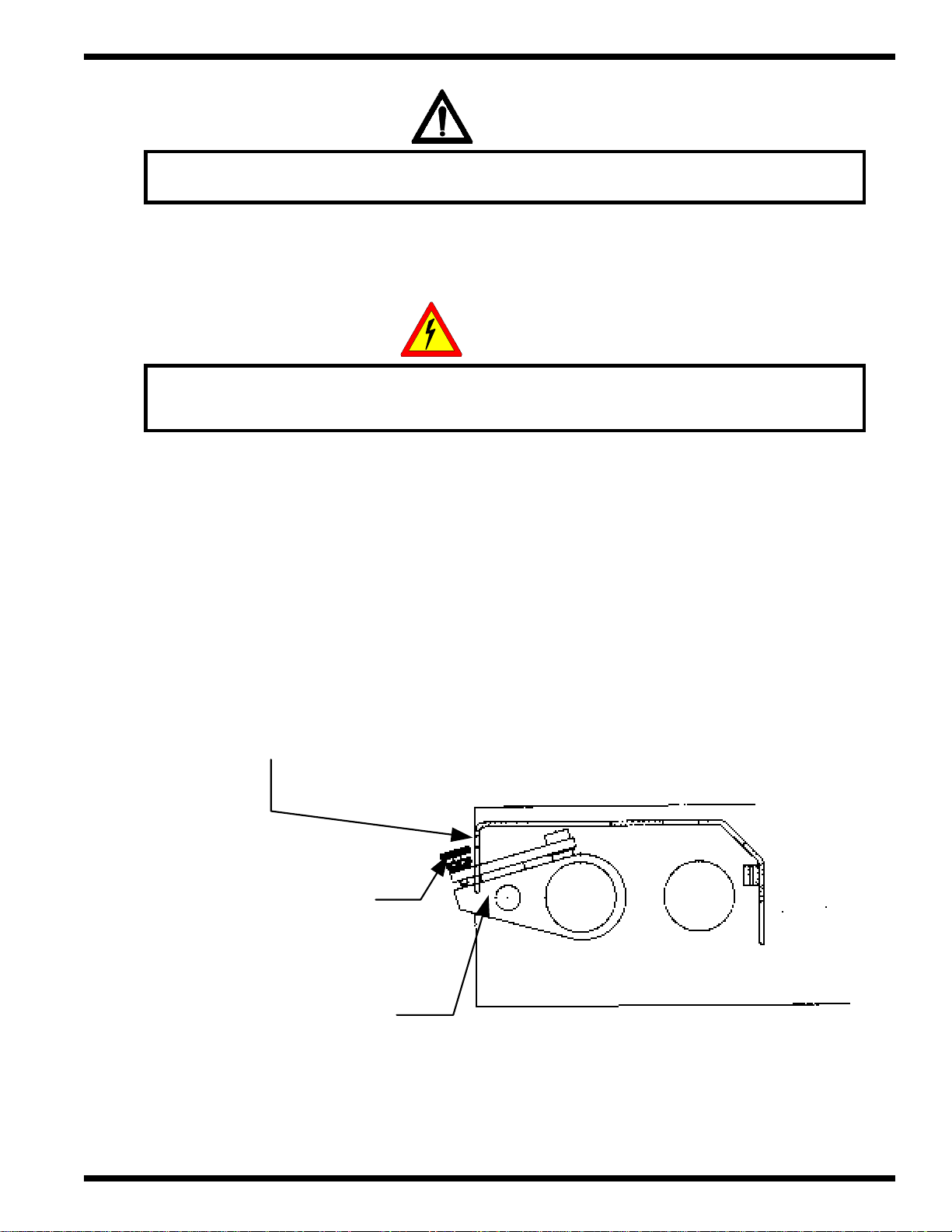
4.6 Becker T4.25 DSK Compressor installation
WARNING
WARNING: Do not place the compressor near machines that have
exhaust air containing oil.
The machine includes a compressor with its own original technical description. It is the rotary wing
type Becker T4.25 DSK compressor , operating without the use of oil. It may not suck in any moistur e, oil,
or any other fluid.
When the compressor has been attached to the machine, check the vacuum, which should be 0.4 Bar
( 1 1.81 inHg ). Adjust the compressor for correct vacuum gauge ( a ) indication. The compr essor may be
switched on and off by means of the switch ( b ), while the machine is being adjusted.
a
b
The pressure and the vacuum valves are adjusted as needed for the operation. When the valves are
completely closed, the compressor has the highest output, electric power is unnecessarily wasted, and wear
and tear are increased.
Page 4 - 8
© GBC Films Group January 2001

4.7 Initial inspection
Remove power to the laminator before performing step ( a ) below. Contact with
electrical components while power is supplied can result in injury or death!
a/ Electrical assembly inspection
– Component mounting
InstallationOrbit™ 2000 Operation and Maintenance Manual
ELECTRICAL
SHOCK
– T erminal security
– Wire tightness
– Circuit breaker wires
ELECTRICAL
SHOCK
Electrical troubleshooting should be left to qualified GBC service technicians!
Electrical shock hazard!
b/ Protective circuit inspection
– The safety of protective circuits may be checked by feeding a current of at least 10 A (50
Hz) from the PEL V source for at least 10 seconds. The test is done between the PE terminal
and various points that are part of the protective circuit. See EN 60204-1, article 20.2.
© GBC Films Group January 2001
Page 4 - 9

Installation
– The voltage measured between the terminal PE and the test points may not exceed
c/ Voltage checks
– from fused disconnect - 240 VAC +/- 10% 3 phase with ground.
– Check each leg, A,B nad C, to ground for proper voltage drop.
Orbit™ 2000 Operation and Maintenance Manual
U =3.3V fo r S= 1.0 square millimeters
U = 2.6V f or S= 1.5 sq. millimeters
U = 1.9V f o r S = 2.5 sq. millimeters
( U ) is the largest drop in voltage and ( S ) is the smallest effective diameter
of the protective conductor in the tested branch of the protective circuit.
– Check main line voltage to locking plug connection on the Orbit™2000.
– Connect plug from Orbit™2000 to electrical supply .
d/ Perform a safety check of all emergency stops, safety latches and lockouts.
– Emergency stop buttons
– Safety shields
– Power on/ off lockout
– T able limit switches
– Feeder head protect from pile-up table
e/ Power-up the Orbit™2000 and confirm that the temperature contoller is illuminated.
If the temperature controller is not illuminated, check the E-Stops, safety latches or lockouts
for activation.
f/ Check all roatations of motors: Feeder Pile-up, Feeder pile-down, main drive and
compressor/ feeder
Page 4 - 10
© GBC Films Group January 2001

g/ Perform a function check of the control panel switches.
h/ Ensure all guides move corr ectly.
i/ Install the stacking table.
InstallationOrbit™ 2000 Operation and Maintenance Manual
© GBC Films Group January 2001
Page 4 - 11

Installation
This page intentionally left blank.
Orbit™ 2000 Operation and Maintenance Manual
Page 4 - 12
© GBC Films Group January 2001

5.0 Operation
WARNING: Only person(s) trained in all aspects of safety and operations
CAUTION: Do not wear ties, loose fit clothing or dangling jewelry. These items
OperationsOrbit™ 2000 Operation and Maintenance Manual
WARNING
may use this equipment.
WARNING
can get caught by the hinged stops or the feed rollers.
This section describes in detail each part of the four areas on the Orbit™ 2000. The four areas
consist of;
( 1 ) 5.1 General information
( 2 ) 5.2 The Feeder Section
( 3 ) 5.3 The Lamination Section
( 4 ) 5.4 The Separator Section.
ATTENTION
Do not operate this equipment unless you have read and understand this
operator manual and have been fully trained in its operation by a
qua lified GB C service technician.
© GBC Films Group January 2001
Page 5 - 1
Operations
Orbit™ 2000 Operation and Maintenance Manual
5.1 General information
Under this section you will find an illustration of the main and secondary operator positions, the
control panel legend and an illustration of the control panel (with the original overlay and the new
overlay).
5.1.1 The main and secondary operator positions
Becker Compressor
T4.25DSK
Secondary
Operation
Page 5 - 2
Secondary
Operation
Main
Operation
© GBC Films Group January 2001

5.1.2 The control panel
Legend
1. Push button - start
2. Push button - stop
3. Speed indicator
4. Potentiometer - speed adjustment by means of the main motor
5. Push button - feeder table UP
6. Push button - feeder table DOWN
7. Push button - pressure roller UP
8. Push button - pressure roller DOWN
OperationsOrbit™ 2000 Operation and Maintenance Manual
9. Laminated sheets counter
10. Temperature regulator of the chrome roller deg C/ deg. F
11. Indicator of missing sheets
12. Switch for changing heating zones on the chrome roller
13. The pulling roller switch, UP/DOWN
14. The cutter drive switch ON/OFF
15. Push button for pulsing the snapping assembly
16. Snapping drive switch
17. Potentiometer - snapping drive speed adjustment
18. Push button - r everse drive
19. Push button - emergency stop
20. Push button - stepping run (slow drive for equipment cleaning)
Please refer to the control panel diagram that r esembles your machine on pages 4 and 5.
The overlay has changed but the functions have remain the same.
© GBC Films Group January 2001
INFORMATION
Page 5 - 3

Operations
Original overlay
Orbit™ 2000 Operation and Maintenance Manual
MACHINE START
1
SPEED
3579
R00
UP
PILE
MACHINE STOP
24
80
90
70
60
50
40
DOWN
100
0
30
10
20
68101214161820
F E E D E R
TEMPERATURE
DOWN
120.0
120.0
UP
PRESSURE ROLL
9999
1113151719
L A M I N A T I N G S E C T I O N
S E P A R A T O R
EMERGENCY
MISSING SHEETS
PULL ROLLERSNAP IMPULSE
50
SEP. SPEED
8"-14"8"-11"
OFF
HEATER
UPDOWN
80
90
70
60
40
30
10
20
ONOFFONOFF
KNIFESEP. MOTOR
100
REVERSEMACHINE INCH
0
Page 5 - 4
© GBC Films Group January 2001

New overlay
OperationsOrbit™ 2000 Operation and Maintenance Manual
START
1
357
SPEED
R00
UP
70
60
50
40
30
DOWN
STOP
24
80
90
100
%
0
10
20
68101214161820
F E E D E R L A M I N A T O RL A M I N A T O R
TEMPERATURE
DOWN
120.0
120.0
UP
9999
9
1113151719
S E P A R A T O R
MISFEED
CLOSEOPEN
50
SNAP SPEED
EMERGENCY STOP
STOP
HEATERS
STARTSTOP
PULL ROLLER
STARTSTOP
SNAP MOTOR
SNAP IMPULSE
80
90
70
60
40
100
%
0
30
10
20
SLOW REV
SLOW FWD
© GBC Films Group January 2001
Page 5 - 5

Operations
Orbit™ 2000 Operation and Maintenance Manual
5.2 Feeder Section
The feeding mechanism consists mainly of the assembly for the lowering and lifting of the feeding
table. In addition, there are the feeding table, the feeding head, fixed face stops, first gate, side stackers,
feeding roller, and the second gate.
The feeder serves the purpose of stacking paper sheets, and is operated by roller chains guided
by two leading spindles. The sheets are taken from the table and inserted into the machine by means of
the feeding head. During lamination the paper is removed from the pile.
The feeding head feeler controls the height of the pile and the lifting of the table. The feed table is
lifted automatically as the paper is removed. One step of lift equals 2 to 3 mm, independently of the
amount of paper . The table lift is either automatically contr olled by the feeding head feeler, or manually
by means of push buttons on the control panel.
"PILE UP” (5) the table lifts
"PILE DOWN” (6) the table lowers
New overlay Oroginal overlay
5
6
Page 5 - 6
© GBC Films Group January 2001

OperationsOrbit™ 2000 Operation and Maintenance Manual
5.2.1 Sheet stacking
Face stacking
The correct face position of the paper stack on the feeding table is provided by the face stackers
( a ), and the first gate ( b ). The sheets must be pushed tight against the surface of the face stackers. One
should make sure that the paper doesn't bend, which can cause problems in the feeding process.
b
a
© GBC Films Group January 2001
Page 5 - 7

Operations
Orbit™ 2000 Operation and Maintenance Manual
Side stacking
The collation of paper pile on the sides is done by side stackers ( c ), which are placed symmetrically .
A slight play must be allowed between the ledges and the paper pile to prevent damage to the paper and
improper feeding. The side stackers are controlled by the knob ( d ) on the operator's side. The arrow
indicates ( e ) the direction of turning for the changing of sheet size. Smaller size in the “ - “ direction,
larger size in the “ + “ direction.
e
d
WARNING
CAUTION: Ensure the path of the side stackers are
clear before making any adjustments.
Page 5 - 8
c
© GBC Films Group January 2001

OperationsOrbit™ 2000 Operation and Maintenance Manual
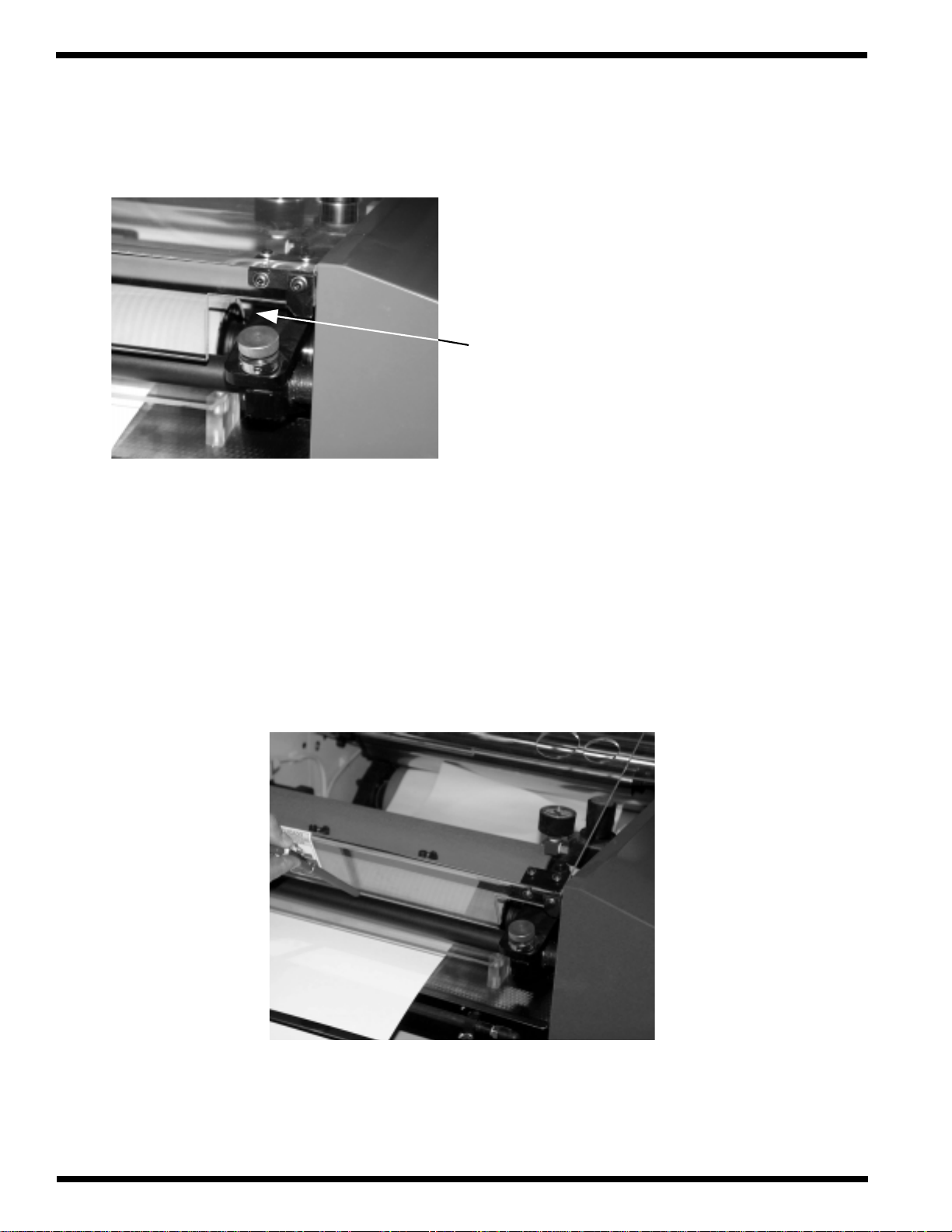
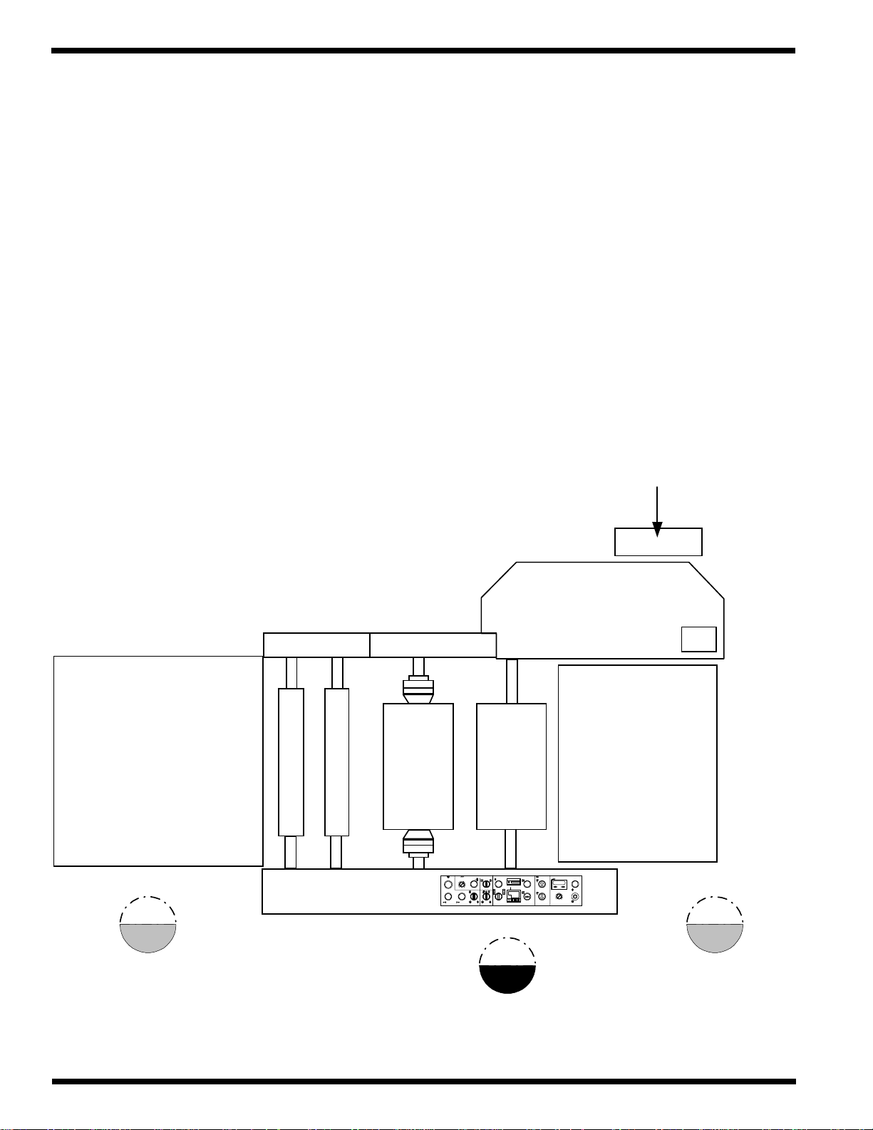
5.2.2 Feeder table positioning
When the paper pile has been loaded, press the “ FEEDER ST ACK/ PILE UP ” button. The table
( f) starts lifting, and its top position is determined by the Paper Pile Height Sensor ( g ), adjust so that
the first gate exceeds the height of the paper by 6 mm.
ATTENTION
The capacity sensor may be adjusted by a qualified service technician only.
First gate
g
6 mm
f
© GBC Films Group January 2001
Page 5 - 9

Operations
5.2.3 The feeding head
WARNING: Press the stop button before performing the following set-up procedure!
Feeding head setup
Orbit™ 2000 Operation and Maintenance Manual
WARNING
Loosen the clamp ( a ) using the handle bar ( b ). Push the head to its back position, away from the
machine. Press the button FEEDER ST ACK/ PILE UP until the paper pile stops at the Paper Pile Height
Sensor ( d ). The feeder foot ( e ) now assumes control and lift the table with paper stack on to its working
position. Move the head so that the rear stops ( c ) touch gently the rear side of the paper stack, and
tighten the clamp.
b
a
Page 5 - 10
c
© GBC Films Group January 2001

OperationsOrbit™ 2000 Operation and Maintenance Manual
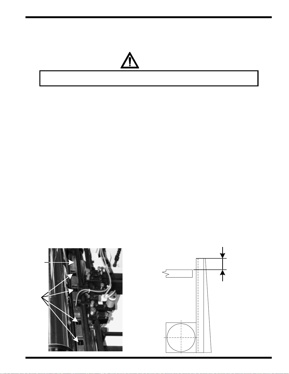
The separating elements setup
1/ The foot of the ( d ) feeler touches the top of the paper stack. Move the strip ( e ) to the stack so
that its front edge is 5 to 7 mm within the paper and 4 to 6 mm above it. For various paper
weights ( e ) must be set to provide for correct paper sheets separation.
5 - 7 mm
d
e
4 - 6 mm
2/ Brushes ( f ) should overlap the paper edge by 2 to 3 mm, and touch the paper very lightly, and
not interfere with paper sheets feathering. For heavier paper use only brushes instead of strips.
ff
© GBC Films Group January 2001
Page 5 - 11

Operations
Orbit™ 2000 Operation and Maintenance Manual
3/ Set up the center suction cups ( g ) by adjusting strips ( e ) so the paper sheets between the cups
are tight.
gg
e
4/ Depending on the paper type, adjust vacuum as needed to lift the sheets via the transport suction
cups by turning the regulator on the Becker compressor. The amount of vacuum can be observed
on the manometer ( h ).
h
5/ The proper air pressure required to feather the paper is set up by means of regulators ( i ) and
( j ).
ij
Page 5 - 12
© GBC Films Group January 2001

OperationsOrbit™ 2000 Operation and Maintenance Manual
6/ Adjust air blowing tubes ( k ) by turning the nut ( l ) so that 10 - 20 sheets at the top of the stack
are feathered.
l
k
7/ Regulator ( m ) sets up the stack height.
m
© GBC Films Group January 2001
Page 5 - 13

Operations
Orbit™ 2000 Operation and Maintenance Manual
Feeding small sheet sizes
WARNING
WARNING: Press the stop button before performing the following set-up procedure!
To feed small sizes of paper sheets, less than the distance between the outside suction cups ( n ),
you must loosen the screw ( o ) and rotate the two outside suction cups ( n ) 90 degrees forward then
secure in place by tightening the screws ( o ). This is necessary to prevent the outside suction cups ( n )
from colliding with the side stacker guides and to not waste vacuum power on suction cups not in contact
with the paper pile.
o
n
n
Page 5 - 14
90
o
© GBC Films Group January 2001

5.2.4 First gate
WARNING
CAUTION: Only a qualified service technician may adjust the first gate.
The first gate assembly is calibrated at the factory and may be field calibrated by a qualified
service technician only. Refer to Section 8 Maintenance.
OperationsOrbit™ 2000 Operation and Maintenance Manual
Function of the first gate
The first gate ( a ) positions the paper ream so that the front is always vertical. While the head is
moving forward, the first gate will tip so as to not interfere with the paper feeding.
© GBC Films Group January 2001
a
Page 5 - 15

Operations
5.2.5 Feed roller assembly
The assembly consists of gravity rollers ( a), accelerating rollers ( b ), plate holders ( c ) and the
sheet overlap sensor ( d ).
d
Orbit™ 2000 Operation and Maintenance Manual
c
a
c
b
Gravity rollers
The gravity rollers are always touching the
paper pressing it against the feed rollers. The position
is factory set, and remains unchanged for all sizes of
paper. For higher paper weights the pressure has to be
increased. For this purpose, a set of weights ( e ) is
supplied as accessories. The weight is simply pulled
out or inserted.
a
b
e
Page 5 - 16
© GBC Films Group January 2001

OperationsOrbit™ 2000 Operation and Maintenance Manual
Accelerating rollers
WARNING
CAUTION: The position of the rollers are set at the factory and does not
require changing, regardless of sheet size.
Accelerating rollers increase the pressure on the feeding roller at the moment the second gate
drops out of the way . Allowing equal pressure to feed paper stock evenly to the chr ome roller and pressure
roller area. The moment of pressure is controlled by the control system and has been factory set. The
spring ( g) determines the pressure.
g
© GBC Films Group January 2001
Page 5 - 17

Operations
Orbit™ 2000 Operation and Maintenance Manual
Plate holders
The plate holders keeps the paper sheet on the lower guiding plate to prevent it from jumping
over the second gate.
Positioning: The machine has three hold-down fingers in total. The position of the middle one does not
change and is factory set. The position of the extreme two change with respect to the size of sheet, and is
adjusted to be about 10 mm distant from the edge of paper, after the screw ( h ) has been loosened. Be
sure to tighten the screw ( h ) after positioning the hold down fingers.
10 10
Adjusting: Pressure is adjusted by moving the holder ( i ) , which is held by screw ( j ). Follow the
procedure below.
j
1/ Loosen the screw ( h ).
h
2/ Insert one sheet of paper ( of the same
specific weight ) to be laminated.
i
Pressure area
3/ Adjust the holders so the finger ( k )
touches the paper without bending.
k
Feeder
4/ Tighten the screw ( h ).
Page 5 - 18
© GBC Films Group January 2001

OperationsOrbit™ 2000 Operation and Maintenance Manual
Sheet misfeed sensor
The sheet misfeed sensor protects the supporting laminating roller from the laminating adhesive.
Check its function daily.
To check the sensor, follow the procedure below.
1/ Take a single sheet of paper, insert it under the sensor ( l ).
2/ Block the sensor repeatedly by sliding the sheet of paper in and out from under the sensor.
3/ The proper function is signaled by the sensor LED, which lights up accordingly.
l
CAUTION: Only a qualified service technician may repair the sheet overlap sensor.
© GBC Films Group January 2001
WARNING
Page 5 - 19

Operations
Overlap adjustment
WARNING: Only person(s) trained in all aspects of the equipment may
CAUTION: NEVER TURN THE DIAL ( t ) WHEN THE MACHINE IS STOPPED!
Orbit™ 2000 Operation and Maintenance Manual
WARNING
perform any operator adjustments.
WARNING
For each paper size, the speed of the feeding head must be adjusted. This is done by manually
turning the dial pointer ( u ) located below the control panel.
Steps
1/ Set the machine to its lowest running speed.
2/ Start the machine.
u
3/ Set the dial pointer ( u ) to a value
just short of the sheet length. ( ie. a 17 in.
sheet, set the dial to 16.5 in. )
4/ Check the overlap.
5/ Should you require a shorter overlap, turn the dial pointer ( u ) slightly toward the “larger sheet
size” direction.
6/ Should you require a longer overlap, turn the dial pointer ( u ) slightly toward the “shorter sheet
size” direction.
7/ After turning the dial pointer ( u ), always wait for 2 to 4 sheets, before continuing with the
adjustments. The variator has a slight delay.
Page 5 - 20
© GBC Films Group January 2001
5.2.6 Second gate
WARNING
CAUTION: Only a qualified service technician may adjust the second gate.
The second gate ( a ) rigisters the sheet and drops out of the way releasing the sheet so that the
overlap of the individual sheets are within the required limits of +/- 1.5 mm.
OperationsOrbit™ 2000 Operation and Maintenance Manual
Position of the second gate
The top edge of the second gate ( a ) must exceed the height of the guide plate ( b ) by 2.3 to 2.7
mm.
b
a
2.3 - 2.7
mm
© GBC Films Group January 2001
Page 5 - 21

Operations
Orbit™ 2000 Operation and Maintenance Manual
5.2.7 Adjustable guide plates
Sliding plates ( a ) guide the sheets into the pressure area helping to minimize wrinkles of the
sheets. They form the sheet before it enters the laminating rollers. The plates position is adjusted by
turning screw ( b ) and nut ( c ).
When working with heavy paper, adjust the plates so the sheet is guided into roller 1/8 in. ( 3.17 mm )
below chrome roller and pressure roller nip.
b
a
c
When working with light paper,adjust the plates so the sheet is guided into roller 1/4 in. ( 6.35 mm )
below chrome roller and pressure roller nip.
b
c
Page 5 - 22
a
© GBC Films Group January 2001

OperationsOrbit™ 2000 Operation and Maintenance Manual
5.3 Lamination section
The lamination section consists mainly of the spool arbor, heating controls, laminating rollers
and the spreader roller.
The laminator serves the purpose of unwind the spool of film via the spool arbor, activating the
thermal adhesive via the chrome roller , laying it on the fed sheets via the laminating r ollers and decurling
the sheets for flat separation via the decurling bar.
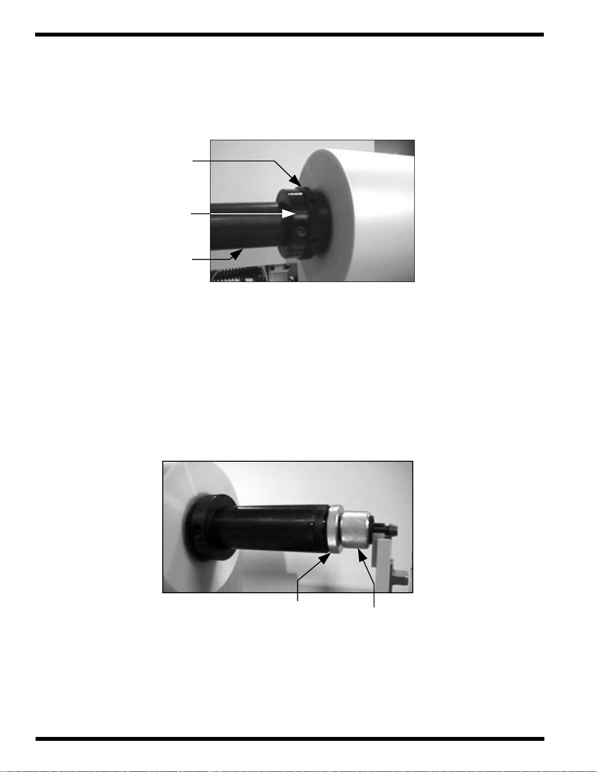
5.3.1 Film roll positioning
WARNING
CAUTION: Do not wear ties, loose fit clothing or dangling jewelry. These items
can get caught the rollers while working around or loading film.
Use the following instructions to load a roll of film and to properly position it:
1/ Set the lateral film adjust nut ( a ) so that the face is in line with the marker ( b ) on the thread of
the spool arbor ( c ). This provides acenter point in which you can adjust the film shaft left or
right to fine tune the film lay down on the sheets.
ab
© GBC Films Group January 2001
c
Page 5 - 23

Operations
g
Orbit™ 2000 Operation and Maintenance Manual
2/ Lower the spool arbor support arm ( d ) by pressing down on the latch ( e ) and pull towards you
from the control side.
e
YOUR MACHINE MAY OR
*
MAY NOT HAVE A
SUPPORT ARM.
d
3/ Loosen the 8 mm screw to the control side conical cone ( f ) and slide it off of the spool arbor
( c ).
c
f
4/ Loosen the nut ( g ) on the drive side conical cone ( h ) and leave loose measurement purposes.
Page 5 - 24
h
© GBC Films Group January 2001

OperationsOrbit™ 2000 Operation and Maintenance Manual
5/ Position the roll of film on the spool arbor ( c ) with respect to the adhesive side (Poly-in or Poly-
out). Refer to Section 6 Applications.
c
f
6/ Replace the control side conical cone ( f ) on the operator’s side and leave the 8 mm screw
loose for movemt.
7/ Measure from operators side/ side frame to paper pile left margin ( a ). Always add 1/8 in.
( 3.17 mm ) to this measurement. Use the measurement just obtained, with the 1/8 in ( 3.17 mm )
addition, to measure the edge of the film ( b ) on the spool arbor to the operators side/ side frame.
X
X + 10 mm
X + 3/8 in.
© GBC Films Group January 2001
b
a
5 mm
Page 5 - 25
Operations
g
Orbit™ 2000 Operation and Maintenance Manual
8/ Tighten the 8 mm screws on both conical cones and tighten the nut ( g ) on the drive side conical
cone ( h ) to secure the roll of film to the spool arbor ( c ).
h
c
9/ Use the lateral film adjust nut ( a ) to fine tune the positioning of the spool arbor with respect to
the pile stack and use the unwind brake nut ( i ) to apply tension to film roll on shaft.
ai
Page 5 - 26
© GBC Films Group January 2001

5.3.2 Heating
WARNING: Keep fingers, hands and other body parts away from the rollers.
OperationsOrbit™ 2000 Operation and Maintenance Manual
WARNING
WARNING: The chrome roller can become extremely hot.
Contact will result in severe burns!
WARNING
Heating is controlled by two means. ( 1 ) by using the temperature controller and ( 2 ) by using
the heat width selection. Heat is delivered from the chrome roll of the laminating rollers.
Temperature adjustment
Adjust the chrome roller temperature for good lamination by pressing or on the
temperature controller.
Actual temperature
( Green numbers )
120.0
120.0
Set temperature
( Red numbers )
Decrease set point
© GBC Films Group January 2001
Increase set point
Page 5 - 27

Operations
Orbit™ 2000 Operation and Maintenance Manual
Heat width selection
For sheet width size between 8 - 11 in. ( 200-280 mm ), set the heater switch ( a ) to 8-11”.
HEATERS
STOP
a
HEATER
OFF
12"-14"8"-11"
New
overlay
Original
overlay
Chrome
roller
12-14 in.
( 305-356 mm )
For sheet width size between 12 - 14 in. ( 305-356 mm ), set the heater switch ( a ) to 12-14”.
HEATERS
STOP
New
overlay
a
HEATER
OFF
12"-14"8"-11"
Original
overlay
Chrome
roller
( 200-280 mm )
8-11 in.
Page 5 - 28
© GBC Films Group January 2001

OperationsOrbit™ 2000 Operation and Maintenance Manual
5.3.3 Laminating rollers
WARNING
WARNING: Keep fingers, hands and other body parts away from the rollers.
The upper chrome roller combined with the lower pressure roller make up the laminating
rollers. The laminating rollers function is to press the adhesive and the film onto the surface of the
sheets. Pressure is regulated by turning the right side regulator ( a ) and/or left side regulator ( b ).
a
b
Independent control of the left and right side pressure enables the operator to contr ol the amount
of pressure applied to the sheets. Equal pressure should be applied for good, clear lamination with no
wrinkling on the paper. Off setting pressures on controls can help with minor wrinkling problems.
© GBC Films Group January 2001
Page 5 - 29

Operations
Adjusting pressure
WARNING: Do not remove any covers or guards while the machine is in operation.
Pressure may be adjusted by two air regulators. One for each side of the pull rollers. To adjust,
follow the procedure below.
Orbit™ 2000 Operation and Maintenance Manual
WARNING
1/ Pull up on the outer part of the regulator knob to unlock.
2/ Turn clockwise to increase pressure and/or counterclockwise to decrease pressure.
3/ Push the outer part of the regulator knob down to lock.
Locked
Unlock
Page 5 - 30
© GBC Films Group January 2001

OperationsOrbit™ 2000 Operation and Maintenance Manual
Automatic pressure cancellation
The closure of the pressure rollers is controlled by the PLC. The PLC will open the pressure
rollers two minutes after the laminator stops to prevent damage to the rubber roller surface.
Automatic pressure cancellation occurs when:
– two ( 2 ) minutes has expired after the machine has been switched off.
– two ( 2 ) minutes has expired form an idle state.
( You can reengage the pressure rollers by pressing the pressur e r oller selector switch to
Close/ Up position. )
UP
PRESSURE ROLL
UP
New overlay
DOW N
DOW N
O r ig in a l ove r la y
( The up indicator is illuminated when the pressure roller is up )
– immediately after an emergency stop push button has been depressed.
– immediately after power has been removed or turned off.
© GBC Films Group January 2001
Page 5 - 31

Operations
Orbit™ 2000 Operation and Maintenance Manual
5.3.4 Spreader roller ( option )
IN F O R MAT ION
Th e follow in g info rm ation is for tho se m ach ines th at a re euip ped
with the op tional sp read er roller.
The spreader roller ( a ) is designed to adjust so the laminate is evenly applied across the
chrome roller. The adjustment is located on the operator side of the machine. Follow the steps below
to adjust the spreader roller:
1/ Loosen the lock nut ( b ).
2/ Turn the adjustment knob ( c ).
– Clockwise to raise the control side of
the spreader roller.
– Counterclockwise to lower the control
side of the spreader roller.
3/ Tighten the lock nut ( b ).
a
c
b
Page 5 - 32
© GBC Films Group January 2001

OperationsOrbit™ 2000 Operation and Maintenance Manual
5.4 Separator section
This section consists of the decurling bar, pull roller, twin knives, snapping assembly and the
stacking table. The separator section runs in conjunction with the laminator and feeder sections.
WARNING
CAUTION: Do not w ear ties, loose fit clothing or dangling jewelry. These items
can get caught the rollers while working around or loading film.
5.4.1 The decurling bar
CAUTION: Do not wear ties, loose fit clothing or dangling jewelry. These items
can get caught the rollers while working around or loading film.
The decurling bar applies or removes curl from the paper sheet following the lamination of
film on the paper by the chrome roller.
WARNING
WARNING: The chrome roller may be hot. Contact will result in severe burns!
© GBC Films Group January 2001
WARNING
Page 5 - 33

Operations
Position of the decurling bar
The position of the decurling bar is dependent of the paper thickness. For thin paper, 60 lb. to
100 lb., the decurling bar effects the web path.
Chrome roller
Orbit™ 2000 Operation and Maintenance Manual
Thin paper
Decurling bar
For thicker papers, 12 pt. to 18 pt., the decurling bar should not effect the web path.
Thick paper
Chrome roller
Decurling bar
Page 5 - 34
© GBC Films Group January 2001

Adjusting the decurling bar
WARNING: Keep fingers, hands and other body parts away from the rollers.
Follow the steps below to adjust the decurling bar:
1/ Loosen the locking lever ( b ).
OperationsOrbit™ 2000 Operation and Maintenance Manual
WARNING
2/ Turn the decurling bar adjustment lever ( a ) with respect to the paper thickness.
3/ Secure the decurling bar in position by tightening the locking lever ( b ).
a
b
For thin paper, radius R3 ( c ) may required if a line is caused by the decurling bar on the
laminated sheets.
© GBC Films Group January 2001
Page 5 - 35

Operations
To change the from R2 to R3 and vice versa,
follow the steps below:
Orbit™ 2000 Operation and Maintenance Manual
1/ Remove the four 8 mm bolts ( a ).
2/ Turn the decurling bar ( b ) with the
desired radius up.
3/ Replace the four 8 mm bolts ( a ).
Effects of the decurling bar
R2
R3
b
a
The sheets should lay flat when exiting the snapping rollers and are collected on the stacking
table.
Correctly decurled sheets Incorrectly decurled sheets
Stacking table
Stacking table
Page 5 - 36
© GBC Films Group January 2001

5.4.2 Pull rollers
WARNING: Keep fingers, hands and other body parts away from the rollers.
CAUTION: Do not w ear ties, loose fit clothing or dangling jewelry. These items
can get caught the rollers while working around or loading film.
OperationsOrbit™ 2000 Operation and Maintenance Manual
WARNING
WARNING
The pull rollers ( a ) provide pull on the paper between the laminating section and the snapping
rollers to achieve straight sheets on the decurling bar.
a
© GBC Films Group January 2001
Page 5 - 37

Operations
Orbit™ 2000 Operation and Maintenance Manual
PAPER PULL ADJUSTMENT
To adjust the paper pull force use the following steps:
1/ Loosen the locking nut ( b ).
2/ Turn the regulating bolt ( c ).
3/ The setting is indicated by the white marker of the control device ( d ) with respect to the
upper roller position scale ( e ).
4/ Tighten the locking nut ( b ) to secure the regulating bolt ( c ).
e
c
b
Page 5 - 38
d
© GBC Films Group January 2001

Paper pull adjustment with regards to sheet weight.
OperationsOrbit™ 2000 Operation and Maintenance Manual
Light pull
© GBC Films Group January 2001
Heavy pull
Page 5 - 39
 Loading...