

Page 1
+
RCS Pylons
Support structures designed for low RCS measurements
+
Unique ogival
shape = extremely
low backscatter
Page 2
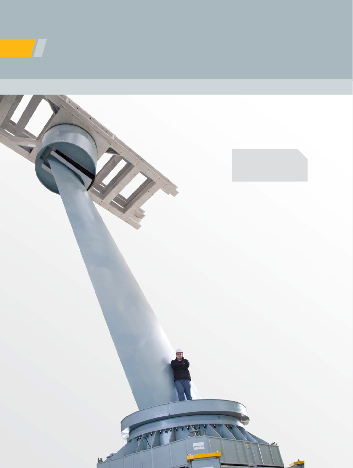
A broad selection of pylons, combined with the choice of rotator types allows for a custom fi t
between pylon and DUT (Device under test). As a result of the unique ogival shape, front and
rear sharp edges, and structure surface accuracy, ORBIT/FR pylons demonstrate extremely low
backscatter, essential for RCS measurements.
Our pylons can be installed on a concrete base, adapter plate, ORBIT/FR positioner, linear slide,
elevator or any combination of the above.
SOLUTION FOR
• RCS measurements
• R&D applications
• Far-fi eld measurements
Key Features
• Ogive ratio: 1:4 standard, 1:6 and 1:7
available for most models
• Pylons for multiple applications
(RCS, Antenna measurement)
• Height: standard from 3 to 70 feet
(1 to 21 meters), or custom order
• Interchangeable tips (Optional)
• Three types of rotator heads: two AZ/EL
and one AZ only
• Load capacity: From 500 - 80,000 lbs.
• Sharp edges: 0.004 - 0.008 inch
• Surface fi nish – 63 microinch
• Optimal power-to volume ratio
• Position feedback readout: synchro or rotary
encoders
AZ/EL
"HAT" TYPE
Pylon structure
AZ/EL
LOW PROFILE
AZIMUTH
ONLY
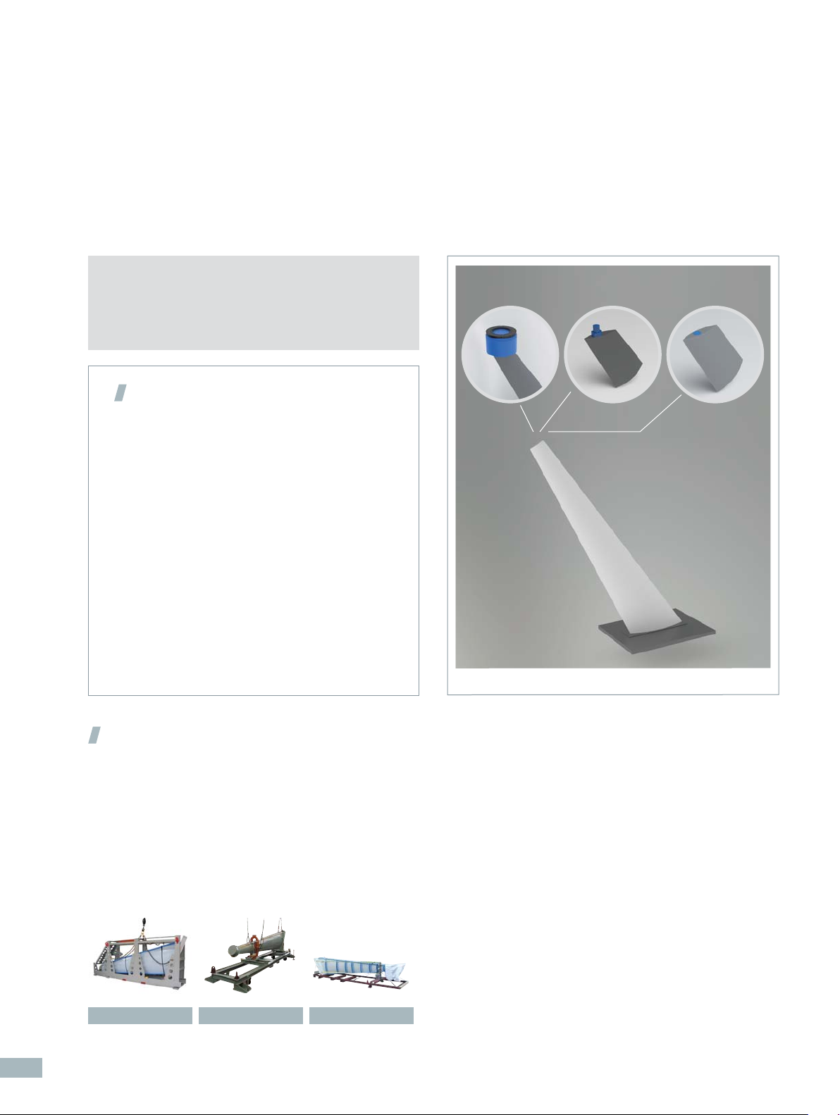
System Confi guration
• Pylon structure: steel, aluminum or combination
of steel and aluminum
• Rotators: AZ/EL and AZ only
• Environment: indoor (standard), outdoor (optional)
• Mini model tower (optional)
• Storage fi xture
• Cover and edges protection kit
• Lifting device for installation
Storage fi xture Lifting device Edges protection kit
2
ORBIT/FR offers three types of DUT rotation mechanisms
(heads): two Azimuth-over-Elevation (AZ/EL) rotators and
one Azimuth (AZ) - only rotator.
Page 3
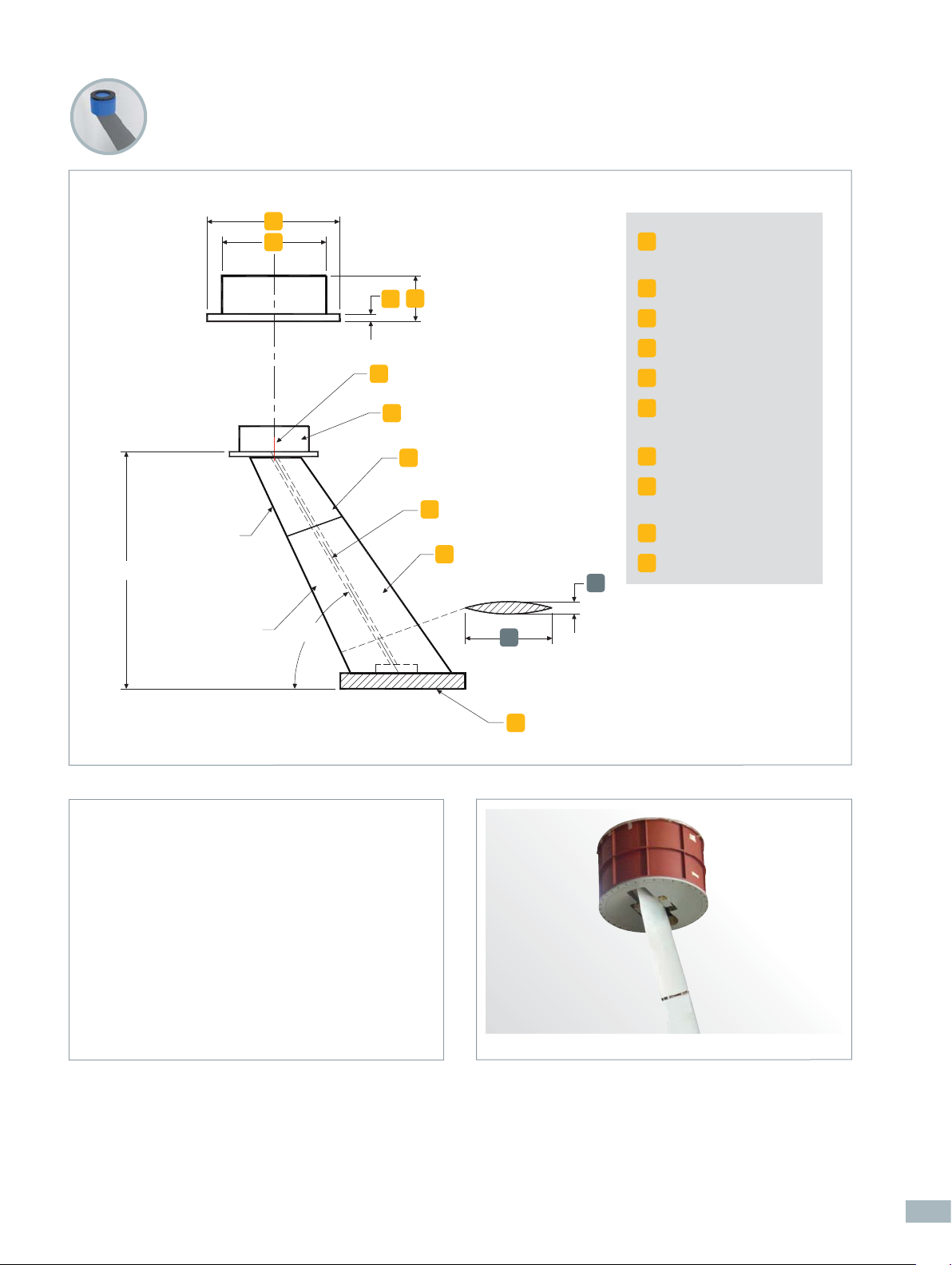
Rotators / AZIMUTH - OVER - ELEVATION (AZ/EL)
"HAT" type rotator with pylon
d1
d2
EDGE SHARPNESS
0.004-0.008 INCH
HEIGHT
d1
Rotator turntable
diameter (flange)
d2
h
t
A
B
C
D
E
OGIVE
w
Rotator base diameter
h
Rotator height
t
Flange thickness
A
Rotator (head)
B
AZ & EL drive and
control system
Tip
C
Through hole
D
for cables
Pylon structure
E
Support base
F
SURFACE FINISH
63 MICROINCH
60°
The “HAT” type pylon rotators are used for heavy
duty DUT measurement.
This unique hat-shaped rotator is positioned on top
of the pylon and provides a mounting interface on its
bottom fl ange to allow the rotator to fi t inside the DUT.
Fitting the rotator inside the DUT minimizes the
rotator’s interference in the measurement results.
Above a 20 ton DUT load, the mounting interface is on
top of the rotator.
l
OGIVE RATIO
w/l=1/4, 1/6, 1/7
F
Pylon with "HAT" type rotator
3
Page 4

AZ/EL Rotator “HAT” Type and Pylon Specifi cations
COMPLETE PYLON
ASSEMBLY MODEL
TIP & ROTATOR
(1)
ONLY
AL-28007-150
AL-28207-150
AL-28010-300
AL-28210-300
AL-28013-600
AL-28213-600
AL-28014-1200
AL-28214-1200
AL-28014-2000
AL-28214-2000
AL-28015-2750
AL-28215-2750
AL-28015-3000
AL-28215-3000
AL-28016-5000
AL-28216-5000
AL-28017-8000
AL-28217-8000
DUT Weight kg 681 1,362 2,724 5,448 9,080 12,485 13,620 22,700 36,300
(max) lbs 1,500 3,000 6,000 12,000 20,000 27,500 30,000 50,000 80,000
Delivered Torque kg-m 104 415 1,078 1,659 3,042 9,678 9,678 20,738 29,034
(EL) ft-lbs 750 3,000 7,800 12,000 22,000 70,000 70,000 150,000 210,000
Delivered Torque kg-m 36 100 173 207 691 4,148 4,148 5,530 6,913
(AZ) ft-lbs 260 720 1,250 1,500 5,000 30,000 30,000 40,000 50,000
Side Bending kg-m 51 142 346 346 1,383 4,148 4,148 5,530 8,295
Moment ft-lbs 370 1,030 2,500 2,500 10,000 30,000 30,000 40,000 60,000
Travel (EL) deg + 5, - 45 + 5, - 45 + 5, - 30 + 5, - 30 + 5, - 30 + 10, - 30 + 10, - 30 + 10, - 30 + 10, - 30
Travel (AZ) deg 360 Continuous
(2)
Accuracy (EL)
Accuracy (AZ)
deg ± 0.05 ± 0.05 ± 0.05 ± 0.05 ± 0.05 ± 0.05 ± 0.05 ± 0.05 ± 0.05
(2)
deg ± 0.03 ± 0.03 ± 0.03 ± 0.03 ± 0.03 ± 0.03 ± 0.03 ± 0.03 ± 0.03
Readout Resolution (EL) deg 0.01 0.001 0.001 0.001 0.001 0.001 0.001 0.001 0.001
Readout Resolution (AZ) deg 0.001 0.001 0.001 0.001 0.001 0.001 0.001 0.001 0.001
Backlash (EL)
Backlash (AZ)
Rotation Speed (EL)
(± 20 %)
Rotation Speed(AZ)
(± 20 %)
(2)
deg 0.07 0.07 0.07 0.07 0.07 0.04 0.04 0.04 0.04
(2)
deg 0.04 0.04 0.04 0.05 0.05 0.04 0.04 0.04 0.04
(2)
(3)
(3)
deg/min 10 4 4 4 4 20 20 20 2
(2)
deg/min 36 30 30 30 50 30 30 20 12
Rotator Height (h) mm 152 183 305 508 635 584 851 1219 1422
in 6 7.2 12 20 25 23 33.5 48 56
Turntable Diameter (d1) mm 327 406 660 559 864 1524 1524 1880 2413
(Flange) in 12.9 16 26 22 34 60 60 74 95
Base Diameter (d2) mm 279 358 597 508 813 1394 1397 1778 2311
in 11 14.1 23.5 20 32 54.9 55 70 91
Flange Thickness (t) mm 8.1 8.1 15.9 25.4 25.4 30 30.0 38.1
in 0.32 0.32 0.63 1 1 1.2 1.2 1.5
(1) Possible to order a tip and rotator only
(2) Data is based on testing in “No Load” position
(3) (+/-20%) refl ects a speed deviation
* Encoder / synchro are applicable for standard models (Optional: Absolute encoder for 6,000 lbs and above)
4
Page 5

Rotators / AZIMUTH - OVER - ELEVATION (AZ/EL)
Low profi le rotator with pylon
h
d1
d2
Rotator base diameter
d1
Rotator turntable
d2
diameter
Rotator height
h
Rotator (head)
A
A
B
C
EDGE SHARPNESS
0.004-0.008 INCH
HEIGHT
SURFACE FINISH
63 MICROINCH
60°
The Low profi le pylon rotators are used for overall
small size and light weight DUT measurement.
The rotator’s drive and position feedback components
(i.e. synchro and encoder) are installed inside the tip
structure and only the “small” head protrudes from the
top.
AZ & EL drive and
B
control system
Tip
C
Through hole
D
for cables
D
E
OGIVE
w
Pylon structure
E
Support base
F
l
OGIVE RATIO
w/l=1/4,1/6
F
The DUT is secured to the top of the rotator.
Pylon with low profi le rotator
5
Page 6

AZ/EL Rotator Low Profi le Type and Pylon Specifi cations
COMPLETE PYLON ASSEMBLY MODEL
(1)
TIP & ROTATOR ONLY
AL-28063-60
AL-28263-60
AL-28062-110
AL-28262-110
AL-28061-220
AL-28261-220
AL-28060-600
AL-28260-600
DUT Weight (max) kg 270 500 1,000 2,724
lbs 600 1,100 2,200 6,000
Delivered Torque (EL) kg-m 50 44 120 830
ft-lbs 360 320 865 6,000
Delivered Torque (AZ) kg-m 5 12 25 97
ft-lbs 33 87 181 700
Side Bending Moment kg-m 7 17 35 140
ft-lbs 50 123 253 1,020
(2)
Travel (EL)
deg 0,-40 0,-40 0,-40 0,-40
Travel (AZ) deg 360 Continuous
(3)
Readout Accuracy (EL)
Readout Accuracy (AZ)
deg ± 0.13 ± 0.13 ± 0.13 ± 0.12
(3)
deg ± 0.05 ± 0.06 ± 0.06 ± 0.06
Readout Resolution (EL) deg 0.02 0.02 0.02 0.02
Readout Resolution (AZ) deg 0.001 0.001 0.001 0.001
Backlash (EL)
Backlash (AZ)
Rotation Speed (EL)
(± 20 %)
Rotation Speed (AZ)
(± 20 %)
(3)
deg 0.06 0.06 0.06 0.06
(3)
deg 0.03 0.06 0.03 0.03
(3)
(4)
deg/min 1 2 1 1
(3)
(4)
deg/min 22 44 22 22
Rotator Height (h) mm 119 140 140 234
in 4.7 5.5 5.5 9.2
Base Diameter (d1) mm 90 116 116 201
in 3.6 4.6 4.6 7.9
Turntable Diameter (d2) mm 60 88 88 136
in 2.36 3.46 3.46 5.36
(1) For orders concerning tip & rotator only, contact our specialists with interface details.
(2) Typical elevation travel is from 0-40 degrees. For other standard travel options, consult our specialists.
(3) Data is based on testing in “No Load” position.
(4) (+/-20%) refl ects a speed deviation
6
Page 7

Rotators / AZIMUTH ONLY
Azimuth only rotator with pylon
A
B
d1
C
D
EDGE SHARPNESS
0.004-0.008 INCH
HEIGHT
SURFACE FINISH
63 MICROINCH
60°
The Azimuth only pylon rotators are used for an
overall small size and light weight DUT in single axis
measurement. They incorporate a positioner located
in the tip of the pylon. The rotator seamlessly
mates with the device under test, preserving the
integrity of the DUT’s test evaluation. DUT elevation adjustments can be implemented manually or
via a motorized elevation positioner/leveling device at
the base of the pylon.
E
OGIVE
w
l
OGIVE RATIO
w/l=1/4,1/6
F
Pylon with azimuth only rotator
Rotator turntable
d1
diameter
Turntable
A
AZ & EL drive and
B
control system
Tip
C
Through hole
D
for cables
Pylon structure
E
Support base
F
AZ only Rotator and Pylon Specifi cations
COMPLETE PYLON ASSEMBLY MODEL
(1)
TIP & ROTATOR ONLY
DUT Weight (max) kg 227 454 1,000
lbs 500 1,000 2,200
Delivered Torque (max) kg-m 2.8 4.1 6.9
ft-lbs 20 30 50
Bending Moment (max) kg-m 41.5 138.3 248.9
ft-lbs 300 1,000 1,800
(2)
Backlash
Readout Accuracy
Readout Resolution deg 0.001 0.001 0.001
Speed deg/min 30 15 12
Azimuth Travel deg 360 continuous
Turntable Diameter (d1) mm 70 70 159
in 2.75 2.75 6.25
(1) For orders concerning tip & rotator only, contact our specialists with interface details
(2) Data is based on testing in “No Load” position
deg 0.03 0.03 0.03
(2)
deg +/- 0.05 +/- 0.05 +/- 0.05
AL-28053-50
AL-28253-50
AL-28055-100
AL-28255-100
AL-28057-220
AL-28257-220
7
Page 8

Pylon ordering information
Pylons can be ordered from our selection of standard models or can be customized to suit customer
specifi c requirements.
To order a complete pylon assembly follow the example in the
table below.
Note the series number of the pylon model, the number
representing the ogive aspect ratio, and the number of feet for
the height of the pylon.
Options
• Slip rings with up to 30 contacts on the azimuth
axis (depends on rotator’s size)
• Rotary joints for “HAT” type rotators: 12 GHz,
18 GHz, 26 GHz and 40 GHz
• Service connector with static cover on top
of the "HAT" type rotators
• Special mounting holes and interfaces
are available upon request
• Special tilting device for installation or
removal of the pylon
Basic models:
• 28xxx-xxx – complete pylon
assembly, hat type
• 282xx-xxx – tip and rotator
only, hat type
• 2806x-xxx – complete low
profi le pylon rotator
• 2826x-xxx – tip and rotator
only, low profi le
Basic model series Aspect ratio Pylon height
AL-28007-150 7 11
Aspect ratios:
• 4 – 1:4 ogive ratio
• 6 – 1:6 ogive ratio
• 7 – 1:7 ogive ratio
Example: AL-28007-150-7-11
Pylon heights:
• Pylon heights from 3 ft to
70 ft are available in standard
sizes in 1 ft increments.
• Pylon heights requiring ½ ft
increments start from 3 ft are
available upon request
www.microwavevision.com / Contact us at: sales@microwavevision.com
8
Product speci cations and descriptions in this document are subject to change without notice.
Actual products may differ in appearance from images shown.
© MICROWAVE VISION 2012
 Loading...