

Page 1
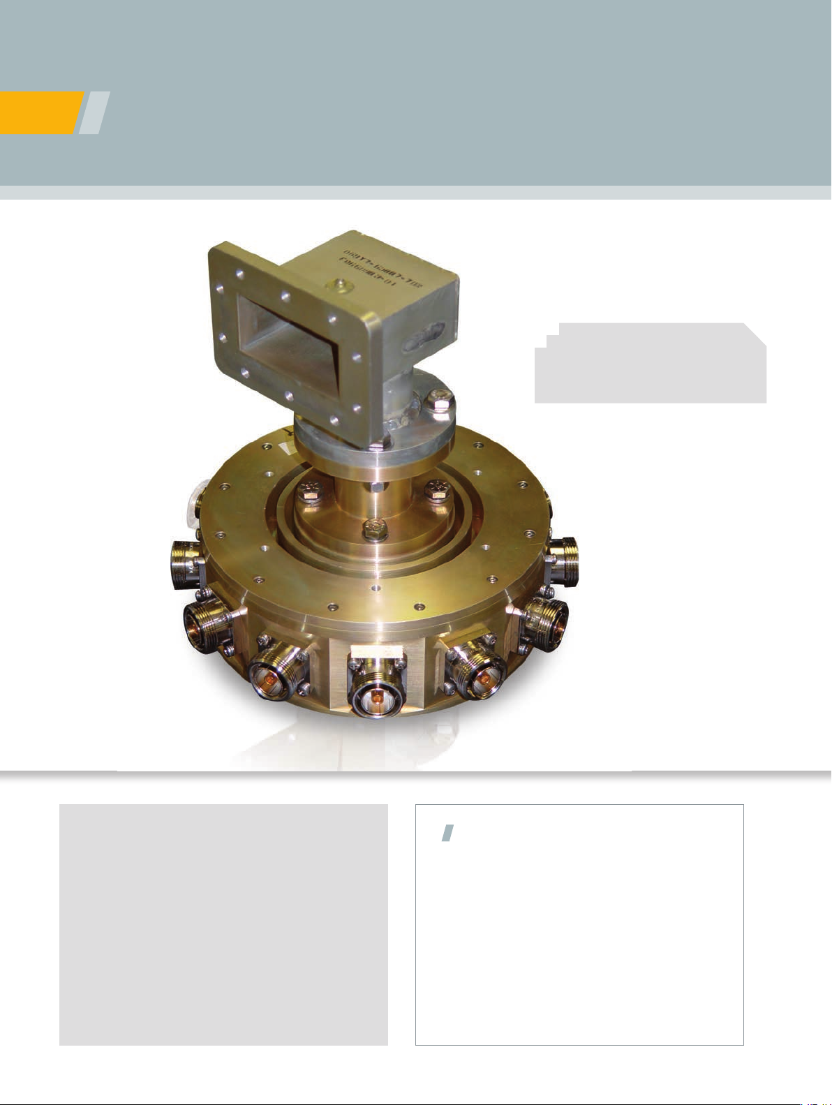
Radial Power Combiners
+
• Hot replacement capability
• Low insertion loss
• High reliability
SOLUTION FOR
• EMI/EMC testing
• EW* transmitters
• Communications
• Radar
• HDTV transmitters
• Phased array antennas
• Air trafc control
• Wireless systems
*Electronic warfare
Model number 752
Features
• Compact geometry
• Hot replacement capability
• Extremely low insertion loss
• Excellent failure tolerance
• Graceful decline in power output if amplifier
modules fail
•
High reliability- high mean time between failures
• Very high power handling capability
• Large number of inputs
• Well suited for harsh environments
Page 2
The demanding requirements of state-of-the-art RADAR, EW and communications systems call for high
power, reliable ampliers. Based on low loss radial waveguide technology, ORBIT/FR’s series 700 combiners
and dividers are precisely machined assemblies qualied to meet the most specic of requirements.
Featuring hot replacement capability and compact geometry, these combiners/dividers are a cost-effective
solution to your high power transmission needs.
ORBIT/FR radial combiners are N-way dielectric nonresonant radial transmission line structures. The inputs are
equally spaced along the circumference of a parallel plate
radial transmission line; output power is extracted at the
center. The inputs are coaxial or rectangular waveguides.
The central output structure is generally coaxial, although
rectangular or higher mode circular waveguides can be
used. Neither isolation resistors nor mode suppressers are
used in the combiners; failure tolerance and hot replacement capability can be achieved without these devices. For
certain applications, generally those at lower frequencies
and lower combining orders, ORBIT/FR has built N-way
matched coaxial Tees. An N-way Tee can be considered
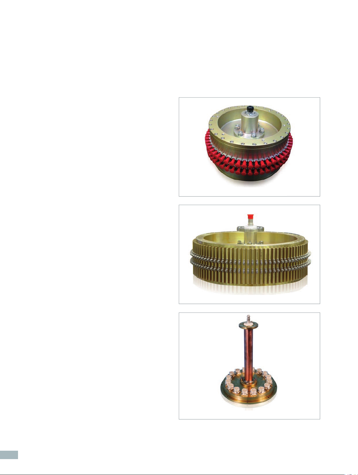
Model number 707
a degenerate case of a radial combiner in which the radial
transmission line is so small in radius that it has become
electrically insignificant.
By virtue of the N-way single step combining geometry,
small size (compared to a corporate combiner), and the
avoidance of resistive and absorptive devices, exceptionally
low combining losses are realized with radial combiners.
Typical combining losses vary from under 0.1 dB for VHF
and low UHF units to 0.3 dB at S-band and 0.5 dB at
K-band. Indeed, losses at VHF and UHF are so low that
they are usually difficult to measure.
The power combiners also feature a “hot replacement”
capability since the device is tolerant of open and short
failures at adjoining ports, meaning that an amplifier can
be replaced while the unit is operational.
Power levels are primarily dictated by the choice of connectors; CW levels in excess of tens of kilowatts are possible
with these devices.
Model number 730
Model number 753
2
Page 3

Specifications
Radial power combiner model summary table
MODEL Frequency Inputs Peak Average Typ. Insertion VSWR Amplitude Phase Application
Range Power Power Loss (dB) (Max.) Imbalance Imbalance
(dB) (deg)
701 20-100 MHz 12 70 KW 20 KW 0.2 dB 1.5:1 ± 0.1 dB ± 1 deg EMC Test Facility
710 100-500 MHz 4 35 KW 0,15 1.25:1 ± 0.1 dB ± 1 deg EW/EMC transmitter
723 225-400 MHz 64 15 KW 0,2 1.3:1 ± 0.15 dB ± 1 deg Communications Transmitter
703 400-450 MHz 25 100 KW 25 KW 0,1 1.2:1 ± 0.1 dB ± 1 deg Scientific Applications
734 400-485 MHz 10 25 KW 3.75 KW 0,15 1.2:1 ± 0.15 dB ± 1 deg Wind shear Radar
706 400-625 MHz 24 50 KW 3.2 KW 0,3 1.25:1 ± 0.15 dB ± 1.5 deg Devider for Phased Array
702 420-430 MHz 20 50 KW 0,15 1.3:1 ± 0.1 dB ± 1 deg Scientific Applications
753 500-600 MHz 16 5 KW 0,15 1.25:1 ± 0.15 dB ± 1 deg -
704 1.2-1.4 GHz 32 50 KW 2 KW 0,15 1.3:1 ± 0.15 dB ± 1.5 deg Air Traffic Control Radar
748 1.25-1.35 GHz 40 65 KW 2 KW 0,3 1.5:1 ± 0.2 dB ± 2 deg Air Traffic Control Radar
741 1.93-1.99 GHz 32 10 KW 500W 0,25 1.25:1 ± 0.25 dB ± 2.5 deg PCS Transmitter
744 13.75-14.5 GHz 12 100 W 0,4 1.4:1 ± 0.3 dB ± 4 deg Satellite Terminal
709 16.3-16.6 GHz 16 40 KW 0,3 1.3:1 ± 0.25 dB ± 4 deg Divider for Phased Array
738 2.5-2.7 GHz 8 2 KW 200 W 0,25 1.3:1 ± 0.25 dB ± 2.5 deg Transmitter
742 2.5-2.7 GHz 12 1 KW 0,2 1.3:1 ± 0.25 dB ± 2.5 deg Transmitter
746 2.5-2.7 GHz 2 2 KW 200 W 0,25 1.3:1 ± 0.25 dB ± 2.5 deg -
707 2.7-2.9 GHz 54 50 KW 3.5 KW 0,3 1.5:1 ± 0.2 dB ± 2 deg Air Traffic Control Radar
708 2.7-2.9 GHz 32 50 KW 3.5 KW 0,3 1.5:1 ± 0.2 dB ± 2 deg Air Traffic Control Radar
711 2.7-2.9 GHz 50 30 KW 3 KW 0,3 1.25:1 ± 0.2 dB ± 3 deg Air Traffic Control Radar
730 2.7-2.9 GHz 90 100 KW 5 KW 0,3 1.5:1 ± 0.25 dB ± 2.5 deg Air Traffic Control Radar
735 2.7-2.9 GHz 16 1 KW 0,2 1.3:1 ± 0.25 dB ± 2.5 deg -
737 2.7-2.9 GHz 18 20 KW 2 KW 0,3 1.5:1 ± 0.2 dB ± 2 deg Radar
705 2.7-3.1 GHz 60 70 KW 7 KW 0,3 1.5:1 ± 0.3 dB ± 4 deg Air Traffic Control Radar
736 2.95-3.45 GHz 8 2 KW 500 W 0,3 1.5:1 ± 0.2 dB ± 2 deg Radar
751 3.0-3.4 GHz 34 3 KW 900 W 0,3 1.5:1 ± 0.2 dB ± 2 deg -
752 3.1-3.4 GHz 12 134 KW 6.7 KW 0,3 1.5:1 ± 0.25 dB ± 2.5 deg -
715 43.5-45.5 GHz 16 25 W 0,5 1.5:1 ± 0.5 dB ± 5 deg Star Terminal
743 5.85-6.425 GHz 16 1 KW 0,3 1.4:1 ± 0.3 dB ± 3 deg Satellite Terminal
733 9-11 GHz 16 100 W 0,3 1.3:1 ± 0.3 dB ± 5 deg Communications Transmitter
ORBIT/FR Customer Satisfaction Focus
ORBIT/FR is a registered ISO 9001: 2008 company
dedicated to customer satisfaction. We maintain
close contact with our customers through the entire
product life cycle, from initial purchase through
project management and post-sales support.
3
Page 4

Have a question? Need more information?
Locate your local ORBIT/FR sales rep at:
http://www.orbitfr.com/usa/content/locate-sales-representative
Or email us at: sales@orbitfr.com
Product specifications and descriptions in this document are subject to change without notice.
Radial Power Combiners Datasheet
Actual products may differ in appearance from images shown.
© MVG 2013
www.microwavevision.com
 Loading...