

Page 1

REFERENCE ANTENNAS
>
Open Boundary Wideband
Quad Ridge Horns
QH Typical 3D cross-Polarization
radiation pattern
REFERENCE ANTENNAS
> Main use:
• Gain calibration
• Wideband probe for far-field test range
• Reflector feed for high gain applications
> Delivered documents:
• Typical performance data (TYMEDATM)
• Measured return loss data and port-to-port coupling
> Surface treatment:
• Alodine 1200 according to MIL-C 5541E class 3
• Blue paint
> Related services:
• Calibration and maintenance
Customization
•
QH Typical 3D co-Polarization
radiation pattern
➊ TECHNICAL PERFORMANCE
• Circular polarization available with external
hybrid coupler
• Uniform gain over operational bandwidth
Dual linear discrimination with high polarization
•
purity and isolation
• Low VSWR
• Wide bandwidth
➋ DESIGN
• Prevents excitation of unwanted higher order
modes in the aperture
• Smooth radiation pattern over the operational
bandwidth
• Lightweight for easy handling
➌ REPEATABILITY
• Stiff and robust mechanical design
Standard SATIMO circular interface for precision
•
centering
• Precision pin for accurate polarization alignment
• Precision machined
• High reliability connector
> Measurement antennas
33
Page 2
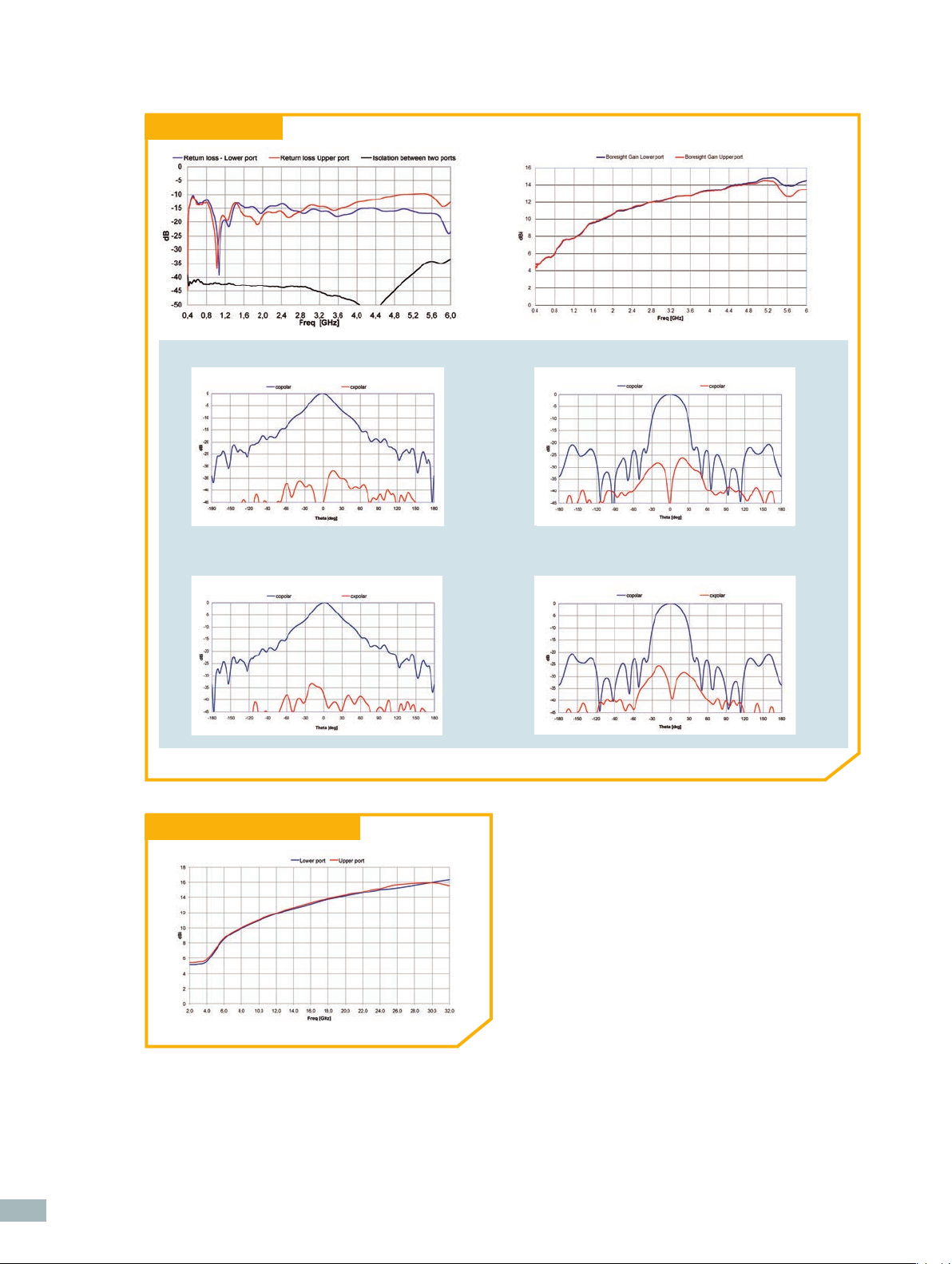
QH 400 performance
❚ @ 3 GHz Normalized Elevation Patterns (E – H plane) - Lower Port
Pattern E-plane lower port @ 3 GHz
❚ @ 3 GHz Normalized Elevation Patterns (E – H plane) - Upper Port
Pattern E-plane PORT 2 @ 3 GHz
Pattern H-plane lower port @ 3 GHz
Pattern H-plane PORT 2 @ 3 GHz
34
QH 2000 boresight gain vs frequency
Page 3

QH 800 performance
❚ @ 6 GHz Normalized Elevation Patterns (E – H plane) - Lower Port
Pattern E-plane lower port @ 6 GHz
❚ @ 6 GHz Normalized Elevation Patterns (E – H plane) - Upper Port
Pattern E-plane PORT 2 @ 6 GHz
Pattern H-plane lower port @ 6 GHz
Pattern H-plane PORT 2 @ 6 GHz
Electrical characteristics
Part number QH 400 QH 800 QH 2000
Type of antenna Open boundary Open boundary Open boundary
wideband wideband wideband
Quad ridge antenna Quad ridge antenna Quad ridge antenna
Frequency range 0.4 – 6.0 GHz 0.8 – 12 GHz 2 – 32 GHz
Average gain 5 – 15 dBi 5 – 15 dBi 5 – 17 dBi
Average VSWR < 1.9:1 < 1.9:1 < 2.5:1 [2-4 GHz]
< 1.9:1 [4-32 GHz]
Average return loss < -10 dB < -10 dB <-7 dB [2-4 GHz]
< -10 dB [4-32 GHz]
Polarization Dual linear Dual linear Dual linear
Cross-polar discrimination > 30 dB > 30 dB [0.8-10.2] GHz
> 25 dB [10.8-12.0] GHz
Port-to-port isolation > 30 dB > 30 dB [0.8-10.8] GHz
> 25 dB [10.8-12.0]GHz
Impedance 50 Ohms 50 Ohms 50 Ohms
> 30 dB
> 30 dB
> Measurement antennas
35
Page 4

Mechanical characteristics
Part number QH 400 QH 800 QH 2000
Dimensions (approx) H x W X L 527 x 527 x 462 mm 264 x 264 x 245 mm 110 x 105 x 105 mm
Weight (approx) 5 kg 1.2 kg 0.24 kg
Connector PC 3.5 Female
Material Aluminum
Treatment Alodine 1200
(1)
PC 3.5 Female
(2)
Aluminum Aluminum
Alodine 1200
Color Blue Blue Blue
Interface Ø 110 mm 110 mm 60 mm
(1) Huber+Suhner type 23 PC35-50-0-51/199UE
(2) Equivalent to MIL-C 5541E class 3
(1)
(2)
PC 3.5 Female
Alodine 1200
(1)
(2)
QH 400, QH 800 interface
M5
67.2
ø110
Mechanical drawing
“W”= “H”
67.2
ø4 H7
ø65
ø35.4
ø60
QH 2000 interface
M4
ø3 H7
ø50
36
“L”
 Loading...