

Page 1

REFERENCE ANTENNAS
>
Magnetic Dipoles
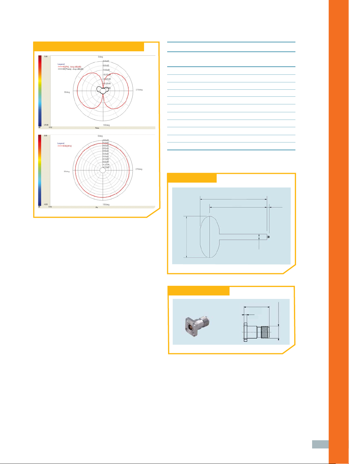
Typical 3D radiation pattern
The magnetic dipole or magnetic
loop antenna is complementary
to the electrical dipole, with a
similar radiation pattern but in
orthogonal polarization.
REFERENCE ANTENNAS
> Main use:
• Gain reference
• Effi ciency reference
• Chamber refl ectivity evaluation: directivity,
cross polarization and radiation pattern
> Delivered documents:
• Typical performance data (TYMEDATM)
•
Measured return loss data
> Surface treatment:
• Alodine 1200 according to MIL-C 5541E class 3
• Blue paint
> Related certifi cation:
• CTIA low gain antenna measurement
> Related services:
• Calibration and maintenance
•
Customization
➊ TECHNICAL PERFORMANCE
• Low loss and high effi ciency
• Azimuth pattern symmetry is within ± 0.1 dB
variation as specifi ed by the CTIA for ripple
testing according to the OTA Test Plan
➋ DESIGN
• Innovative low loss structure with a protective
external radome
• Excellent rotation symmetrical structure
minimizing cross polarization level
• The radiating structure is orthogonal to the feeding
line, minimizing cable and feed point interaction
• The radiating structure is entirely metallic without
the use of external discrete components
• Innovative choke design further reduces cable
interaction by attenuating the natural return
currents from the magnetic dipole
➌ REPEATABILITY
• Stiff and robust mechanical design
• Precision machined
• High reliability connector
18
Page 2
MD Typical elevation and azimuth radiation pattern
Electrical characteristics
Part number MD
Type of antenna Magnetic dipole
Available frequencies 0.65 – 5.5 GHz
Gain variation over azimuth <± 0.1 dB
Peak directivity 2.1 dBi (Typ)
Peak gain 1.6 dBi (Typ)
Effi ciency
VSWR
Return loss
Cross polar level < 20 dB
Impedance 50 Ohms
Frequency BW (Ret. Loss <-10 dB) 5 % (Typ)
(1) at the labeled center frequency
(1)
~ 88 % (Typ)
(1)
1.9:1
(1)
< -10 dB
Mechanical drawing
“A”
“B”
“C”
“D”
Connector type & interface
Type 23 PC35-50-0-51/199 UE
1.6
(.063)
13.3
(.524)
“d”
> Measurement antennas
1/4-36 UNS-2A
19
Page 3

“A” = Total length
“B” = Phase center position
“C” = Connector length
“D” = Maximum diameter
“d” = Minimum diameter
Mechanical characteristics
Part number Frequency A mm B mm C mm D mm d mm Connector Weight
range Type
1
MD 665 652 – 678 MHz 239.2 207.8 8.2 135 18 PC 3.5 Female
MD 720 715 – 735 MHz 216.5 185.1 8.2 135 18 PC 3.5 Female1 400 g (approx)
MD 836 824 – 860 MHz 217.2 185.8 8.2 135 18 PC 3.5 Female1 400 g (approx)
MD 880 870 – 900 MHz 217.2 185.8 8.2 135 18 PC 3.5 Female1 400 g (approx)
MD 900 880 – 920 MHz 217.2 185.8 8.2 135 18 PC 3.5 Female1 400 g (approx)
MD 945 925 – 965 MHz 217.2 185.8 8.2 135 18 PC 3.5 Female1 400 g (approx)
MD 1230 1205 – 1255 MHz 155.9 124.5 8.2 135 18 PC 3.5 Female1 350 g (approx)
MD 1575 1545 – 1605 MHz 121.1 106.0 8.2 65 14 PC 3.5 Female1 200 g (approx)
MD 1730 1695 – 1755 MHz 109.7 94.6 8.2 65 14 PC 3.5 Female1 200 g (approx)
MD 1800 1765 – 1830 MHz 109.7 94.6 8.2 65 14 PC 3.5 Female1 200 g (approx)
MD 1840 1810 – 1875 MHz 109.7 94.6 8.2 65 14 PC 3.5 Female1 200 g (approx)
MD 1880 1850 – 1910 MHz 109.7 94.6 8.2 65 14 PC 3.5 Female1 200 g (approx)
MD 1960 1935 – 1995 MHz 109.7 94.6 8.2 65 14 PC 3.5 Female1 200 g (approx)
MD 2050 2010 – 2085 MHz 109.7 94.6 8.2 65 14 PC 3.5 Female1 200 g (approx)
MD 2140 2110 – 2170 MHz 109.7 94.6 8.2 65 14 PC 3.5 Female1 200 g (approx)
MD 2350 2300 – 2400 MHz 109.7 94.6 8.2 65 14 PC 3.5 Female1 200 g (approx)
MD 2450 2400 – 2483 MHz 109.7 94.6 8.2 65 14 PC 3.5 Female1 200 g (approx)
MD 2600 2565 – 2670 MHz 109.7 94.6 8.2 65 14 PC 3.5 Female1 200 g (approx)
MD 2800 2730 – 2870 MHz 109.7 94.6 8.2 65 14 PC 3.5 Female1 200 g (approx)
MD 3600 3530 – 3670 MHz 174.6 157.3 8.2 65 14 PC 3.5 Female1 250 g (approx)
MD 5500 5363 – 5637 MHz 171.6 156.5 8.2 65 14 PC 3.5 Female1 250 g (approx)
400 g (approx)
20
(1): Huber+Suhner type 23 PC35-50-0-51/199UE
 Loading...