

Page 1
G-DualScan
Page 2

I G-DualScan
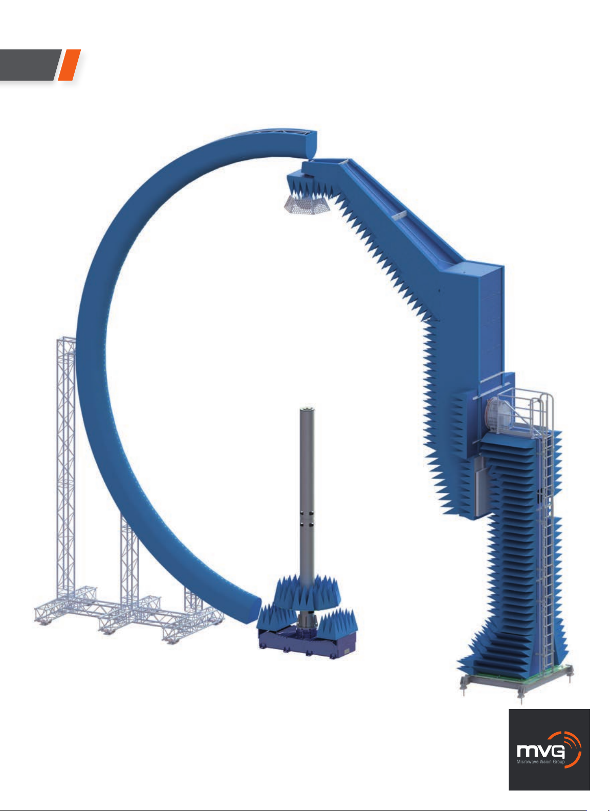
G-DualScan represents a step forward in spherical near-field measurements. It measures antennas
with large dimensions and analyzes a very broad range of frequency bands from 200 MHz
to 18 GHz. It consists of a single-probe gantry arm and a multi-probe arch up to 12 meters (40
feet) in diameter.
+
Measures antennas with large dimensions
and analyzes a very broad range
of frequency bands
SOLUTION FOR
• Antenna Measurement
• Pulsed Measurement
• Phased Array Antenna Measurement
Main features
Technology
• Near-field / Spherical
Measurement capabilities
• Gain
• Directivity
• Beamwidth
• Cross polar discrimination
• Sidelobe levels
• 3D radiation pattern
• Radiation pattern in any polarization (linear or circular)
• Antenna efficiency
System configurations
Software
Measurement control, data acquisition and post processing
■ MiDAS
SatEnv
959 Spectrum (North America only)
Equipment
■ Mixer unit
■ N-PAC
■ Primary synthesizer
■ Auxiliary synthesizer
■ Amplification unit
■ Transfer switching unit
■ Power and control unit
■ Probe array power supply
■ Heavy DUT positioner, azimuth over goniometer
■ Elevation positioner for gantry arm
■ Positioner controller
■ E-Stop unit
■ Local control unit
■ Real time controller
■ Control interface unit
■ Uninterruptible power supply
■ Instrumentation rack
■ Ethernet switch
AUT Port switch
Frequency bands
• Single-probe: 200 MHz - 18 GHz, divided in sub-bands
(up to 40 GHz upon request)
• Multi-probe: 400 MHz - 6 GHz (400 MHz - 18 GHz
or 70 - 400 MHz upon request)
Max. size of DUT
• 7 m diameter
Max. weight of DUT
• 1000 kg
Typical dynamic range
• 50 dB
Oversampling
• Elevation tilt of the AUT
Add-on
Shielded anechoic chamber*
Accessories
2 PCs:
■ Data acquisition and analysis computer inside the chamber
Secondary computer outside the chamber for remote control
with extra analysis license (optional)
■ Metallic mast for calibration space
Reference antennas: wideband horns, standard gain horns etc.
Probes for gantry arm
Services
■ Installation and calibration
■ Project management
■ Training
■ Warranty
Post warranty service plans**
* See AEMI/ Rainford EMC Included Optional Required
Systems catalogs for more information
** Refer to Orbit/FR service brochure for more information
127
2
Page 3

System overview
I G-DualScan
INSTRUMENTATION ROOM CHAMBER
Data Acquisition
& Processing Platform
Triggers
Primary
Synthesizer
Real Time
Controller
N-PAC
Mixer Unit
USB
Triggers
Amplication
Unit
GPIB
1
5
Transfer
Switching Unit
2
4
3
RF
Switch
Auxiliary
Synthesizer
Rx
Tx
Positioner
Controller
G-DualScan uses a Vector Network Analyzer as the
RF source/receiver for antenna measurements. The
Amplification Unit has RF amplifiers for each of the RX
and TX channels. G-DualScan uses a Transfer Switching
Unit to emit from the AUT to the probe(s) or vice versa.
A dedicated RF switch allows the selection of either the
single-probe or the multi-probe set-up. The Positioner
Controller drives the goniometer and azimuth axes for the
AUT, and the elevation axis for the gantry arm. Measurements can be performed in both continuous wave and
optional pulsed mode. In the case of phased array antenna measurement, the system utilizes an optional real time
controller to control and synchronize the measurement
system with the device under test.
128
3
Page 4

Standard system components
Multi-probe
half arch
A choice of probes…
• A semi-circular arch of 1280 cm
internal diameter with 128
channels (127 probes +
1 reference channel) operating
from 400 MHz up to 6 GHz
Single-probe
gantry arm
• A single-probe scanner
operating from 200 MHz to
18 GHz in 3 sub-bands
(up to 40 GHz upon request)
I G-DualScan
DUT positioner
• An azimuth turntable that
enables 360° rotation of
the DUT and a goniometer
to calibrate the system and
perform oversampling.
Azimuth axis: Accuracy
(± 0.005 deg) and max. speed
(7.8 deg/s)
See the Goniometer
section page 86
Antennas
• A complete range of
measurement probes
(dual polarized) and reference
antennas (horns, standard gain
horns) is available
MVG antenna catalog
Absorbers
and anechoic
chambers
G-DualScan in a shielded anechoic chamber
• A choice of standard, adapted
and specialty absorbers
• Anechoic chambers with
integrated design, production,
installation and testing services
AEMI absorber catalog
129
43
Page 5

System specifications*
I G-DualScan
10 dBi AUT 20 dBi AUT 30 dBi AUT
PEAK GAIN ACCURACY
0.2 - 0.4 GHz ± 1.5 dB ± 1.46 dB ± 1.46 dB
0.4 - 1 GHz ± 0.9 dB ± 0.86 dB ± 0.86 dB
1 - 18 GHz ± 0.5 dB ± 0.44 dB ± 0.42 dB
PEAK GAIN REPEATABILITY ± 0.3 dB ± 0.3 dB ± 0.3 dB
- 10 dB SIDELOBES ACCURACY
0.4 - 0.8 GHz ± 0.8 dB ± 0.5 dB ± 0.4 dB
0.8 - 1 GHz ± 0.7 dB ± 0.5 dB ± 0.4 dB
1 - 6 GHz ± 0.7 dB ± 0.5 dB ± 0.4 dB
6 - 18 GHz ± 0.7 dB ± 0.5 dB ± 0.4 dB
Measurement time comparison
Typical ‘on the fly’ measurement
Single-probe set-up
10 dBi AUT 20 dBi AUT 30 dBi AUT
- 20 dB SIDELOBES ACCURACY
0.4 - 0.8 GHz ± 2.6 dB ± 0.8 dB ± 0.5 dB
0.8 - 1 GHz ± 2.1 dB ± 0.7 dB ± 0.5 dB
1 - 6 GHz ± 2.1 dB ± 0.7 dB ± 0.5 dB
6 - 18 GHz ± 2.1 dB ± 0.7 dB ± 0.5 dB
- 30 dB SIDELOBES ACCURACY
0.4 - 0.8 GHz - ± 2.6 dB ± 0.8 dB
0.8 - 1 GHz - ± 2.1 dB ± 0.7 dB
1 - 6 GHz - ± 2.1 dB ± 0.7 dB
6 - 18 GHz - ± 2.1 dB ± 0.7 dB
*Specications given according to the following assumptions:
- The standard deviation of the reference data is 0.1dB
- The S11 & the directivity of the reference antenna are the same as those of the AUT
- Absorbers in the anechoic room are AEP-36 from AEMI.
- The given peak gain accuracy values are for 0 dB AUT efciency
Typical ‘on the fly’ measurement
Multi-probe set-up
Frequency Number of measured Measurement
frequencies time (in hours)
3 GHz, AUT Diameter is 3 m 10 1.2
6 GHz, AUT Diameter is 5 m 10 3.8
Mechanical characteristics
Single-probe
Positioner series AL–1760–1P
Bending moment 20,000 ft-lbs
2,765 kg-m
Operating load 20,000 Ibs
9,090 kg
Delivered torque 2,800 ft-Ibs
390 kg-m
Withstand torque 4,200 ft-Ibs
580 kg-m
Drive power ¾ hp
Nominal speed 0.5 rpm
Standard angle transducer format Dual speed synchro
Standard accuracy ± 0.02°
Maximum backlash 0.05°
Frequency Number of measured Measurement
frequencies time (in hours)
3 GHz, AUT Diameter is 3 m 10 0.1
6 GHz, AUT Diameter is 5 m 10 1.5
Probe array
The probe array mechanical characteristics are limited to
• Internal diameter of 12.8 m
• Angle between the probes is 1.304°
130
5
Page 6

I G-DualScan
Maximum diameter of DUT* (m) Single-probe
FREQUENCY ANGULAR STEP IN DEGREES
(GHz) 1.5° 2° 3° 5° 10°
sampling sampling sampling sampling sampling
0.4 9,04 9,04 9,04 8,59 4,30
1 9,04 8,59 5,73 3,44 1,72
2 6,59 4,30 2,86 1,72 0,86
3 4,39 2,86 1,91 1,15 0,57
4 3,30 2,15 1,43 0,86 0,43
5 2,64 1,72 1,15 0,69 0,34
6 2,20 1,43 0,95 0,57 0,29
7 1,88 1,23 0,82 0,49 0,25
8 1,65 1,07 0,72 0,43 0,21
9 1,46 0,95 0,64 0,38 0,19
10 1,32 0,86 0,57 0,34 0,17
11 1,20 0,78 0,52 0,31 0,16
12 1,10 0,72 0,48 0,29 0,14
13 1,01 0,66 0,44 0,26 0,13
14 0,94 0,61 0,41 0,25 0,12
15 0,88 0,57 0,38 0,23 0,11
16 0,82 0,54 0,36 0,21 0,11
17 0,78 0,51 0,34 0,20 0,10
18 0,73 0,48 0,32 0,19 0,10
* Gantry Arm Arch with 11,3 m internal diameter
Maximum diameter of DUT* (m) Multi-probe
FREQUENCY NUMBER OF OVERSAMPLING
(GHz) X1 X2 X3 X5 X10
0.4 10,24 10,24 10,24 10,24 10,24
1 10,24 10,24 10,24 10,24 10,24
2 6,59 10,24 10,24 10,24 10,24
3 4,39 8,79 10,24 10,24 10,24
4 3,30 6,59 9,89 10,24 10,24
5 2,64 5,27 7,91 10,24 10,24
6 2,20 4,39 6,59 10,24 10,24
7 1,88 3,77 5,65 9,42 10,24
8 1,65 3,30 4,94 8,24 10,24
9 1,46 2,93 4,39 7,32 10,24
10 1,32 2,64 3,95 6,59 10,24
11 1,20 2,40 3,59 5,99 10,24
12 1,10 2,20 3,30 5,49 10,24
13 1,01 2,03 3,04 5,07 10,14
14 0,94 1,88 2,82 4,71 9,42
15 0,88 1,76 2,64 4,39 8,79
16 0,82 1,65 2,47 4,12 8,24
17 0,78 1,55 2,33 3,88 7,75
18 0,73 1,46 2,20 3,66 7,32
* Half Arch with 1,304° between probes, 12,8 m internal diameter
Product specications and descriptions in this datasheet are subject to change without notice.
Actual products may differ in appearance from images shown.
Copyright MVG 2014
131
65
 Loading...