

Page 1
Field Probes
Field Probes Overview
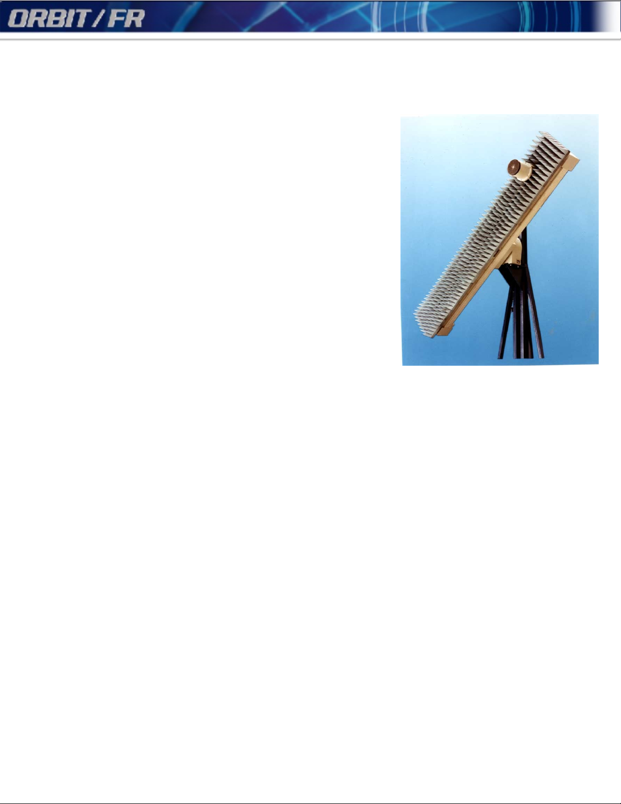
Aperture Field Probe systems are used to evaluate the extraneous signals
which exist in the location of the Device Under Test due to reflections, other
transmitting sources, etc.
The Aperture Field Probe can rest on a polarization positioner which moves on
a linear carriage, which is mounted on another polarization positioner. Thus a
circular area can be observed at any location in any desired polarization.
The carriage rotation is achieved by a standard polarization positioner, AL-5601P, AL-760-1P, AL-1260-1P or AL-1760-1P according to series and carriage
size.
The linear slide is used for the radial motion.
The main purpose of the probe polarization positioner is to keep the probe in a
constant polarization by rotating in reverse direction to the Field Probe
polarization positioner. For example, if the probe is in vertical polarization at a
given position, and the Field Probe rotates 30°, then the probe itself rotates -30°
to retain the same vertical polarization. The probe polarization positioner can
also serve to sample the field at several polarizations at any given point.
It is recommended that the probe be mounted on the smallest polarization
positioner which complies with the probe's mechanical constraints (weight and
bending moment).
Options for both series include:
Rotary joint for the probe positioner
RF cable installation
Probe fixtures
Replace the synchro transducer with Incremental rotary encoder. This option
is required when using AL-060-1P or AL-160-1P positioners
Preparation and installation of absorbing material
Lightweight: AL-4607 Series
High Accuracy: AL-4608 Series
AL-4608-1
Page 2
Field Probes
Lightweight Aperture Field Probe AL-4607 Series
The AL-4607-1 lightweight aperture field probe has two linear travel ranges: 54" or 108". The
model with 54" linear travel can be mounted on an AL-560-1P polarization positioner for a
maximum load of 20 lbs, or on an AL-760-1P for a maximum load of 50 lbs.
The model with 108" linear travel is mounted on the AL-760-1P for a maximum load of 20 lbs.
Options
EN001 Replace synchro readout with rotary incremental encoder for all axes. Required
when ordering with AL-160-1
PRB Probe holder
RFC RF cable installation through Field Probe
RJ12L Coaxial single-channel Rotary Joints, DC-12.4 GHz (including precision RF path, N-
type connector and mounting flange), for same or lower axis.
RJ18L Coaxial single-channel rotary joints, DC-18 GHz (including precision RF path, SMA-
type connector and mounting flange) for same or lower axis.
RJ40L Coaxial single-channel rotary joints, DC-40 GHz (including precision path, K-type
connector and mounting flange), for same or lower axis.
RJ12U Coaxial single-channel rotary joints, DC-12.4 GHz (including precision RF path, N-
type connector and mounting flange), for upper Azimuth positioners.
RJ18U Coaxial single-channel rotary joints, DC-18 GHz (including precision RF path, SMA
connector and mounting flange), for upper Azimuth positioners.
RJ40U Coaxial single-channel rotary joints, DC-40 GHz (including precision RF path, K-type
connector and mounting flange), for upper Azimuth positioners.
AL-4607 Series
Al-4607-1 Lightweight Field Probe
Ordering Information
Supplied Accessories
Page 3
Field Probes
Lightweight Aperture Field Probe AL-4607 Series (Cont’d)
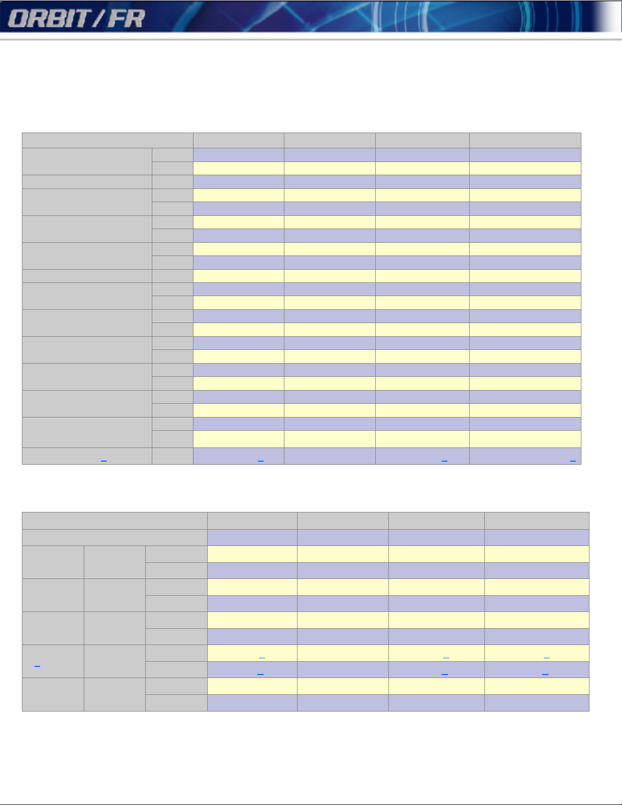
Specifications:
AL-4607-1-560-54 AL-4607-1-760-54 AL-4607-1-760-108 AL-4607-1-1260-108
Travel
Polarization Positioner AL-560-1P AL-760-1P AL-760-1P AL-1260-1P
Max. Load
Carriage Bending Moment
Max. Carriage Speed
Carriage Motor hp 1/16 1/16 1/16 1/16
Backlash
Carriage Weight
Data Take-off Accuracy
Planarity
Deflection at max. Load
Repeatability
Probe Positioner 1 AL-160-1 1 AL-160-1P AL-160-1 1 AL-160-1 AL-260-1P 1
mm ±1,371.6 ±1,371.6 ±2,743,2 ±2,743,2
in ±54 ±54 ±108 ±108
kg 9 23 9 9
lbs 20 50 20 20
m-kg 5.5 8.3 5.5 5.5
ft-lbs 40 60 40 40
m/min 5 5 5 5
ft/min 15 15 15 15
mm 0.4 0.4 0.4 0.4
in 0.0016 0.0016 0.0016 0.0016
kg 96 96 125 125
lbs 210 210 275 275
mm ±0.5 ±0.5 ±1.0 ±1.0
in ±0.02 ±0.02 ±0.04 ±0.04
mm ±1.5 ±1.5 ±3.0 ±3.0
in ±0.06 ±0.06 ±0.12 ±0.12
mm ±1.5 ±1.5 ±3.0 ±3.0
in ±0.06 ±0.06 ±0.12 ±0.12
mm ±0.25 ±0.25 ±0.5 ±0.5
in ±0.01 ±0.01 ±0.02 ±0.02
AL-4607 Series
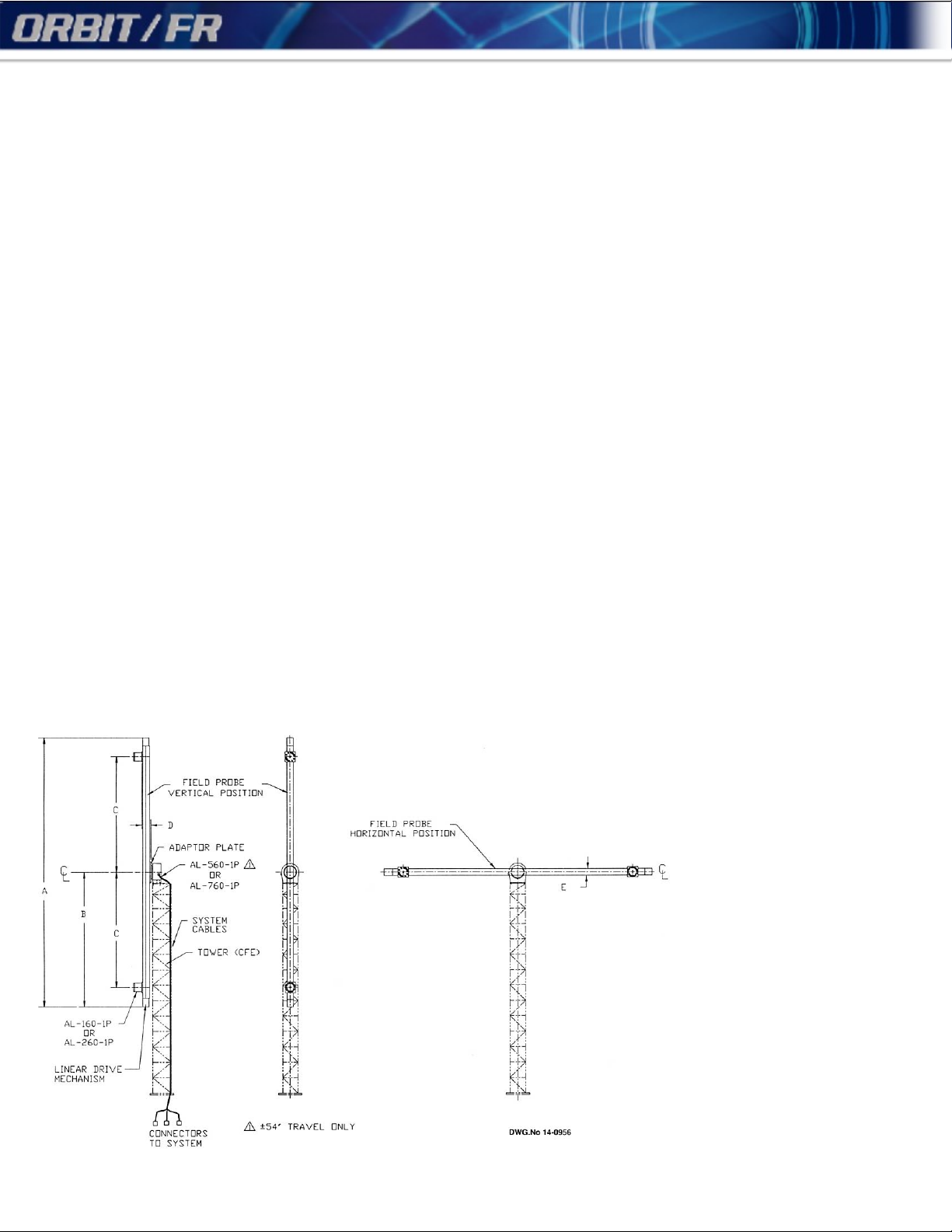
Dimensions:
AL-4607-1-560-54 AL-4607-1-760-54 AL-4607-1-760-108 AL-4607-1-1260-108
Outline Dimensions Drawing Number 11-2450 11-2450 11-2449 11-2449
A Length
B Radius
C Travel
D 1 Thickness
E Width
mm 3,600 3,600 6,400 6,400
in 141.7 141.7 252 252
mm 1,800 1,800 3,200 3,200
in 70.87 70.87 126 126
mm 1,372 1,372 2,743 2,743
in 54 54 108 108
mm 113 1 113 113 1 113 1
in 4.4 1 4.4 4.4 1 4.4 1
mm 160 160 160 160
in 6.3 6.3 6.3 6.3
Page 4

Field Probes
High-Precision Aperture Field Probe
The AL-4608-1 high-precision aperture field probe has two linear travel ranges: 48" or 100". These
high precision models are extremely accurate and have very low deflection under maximum load.
The models with 48" linear travel can be mounted on an AL-760-1P polarization positioner for
maximum load of 50 lbs, or on AL-1260-1P for maximum load of 100 lbs.
The models with 100" linear travel can be mounted on an AL-1260-1P polarization positioner for a
maximum load of 50 lbs, or on an AL-1760-1P for a maximum load of 100 lbs.
Options
ABI01 Installation of absorbing material.
EN001 Replace synchro readout with rotary incremental encoder for all axes. Required when
ordering with AL-160-1
PRB Probe holder
RFC RF cable installation through Field Probe
RJ12L Coaxial single-channel Rotary Joints, DC-12.4 GHz (including precision RF path, N-
type connector and mounting flange), for same or lower axis.
RJ18L Coaxial single-channel rotary joints, DC-18 GHz (including precision RF path, SMA-
type connector and mounting flange) for same or lower axis.
RJ40L Coaxial single-channel rotary joints, DC-40 GHz (including precision path, K-type
connector and mounting flange), for same or lower axis.
RJ12U Coaxial single-channel rotary joints, DC-12.4 GHz (including precision RF path, N-type
connector and mounting flange), for upper Azimuth positioners.
RJ18U Coaxial single-channel rotary joints, DC-18 GHz (including precision RF path, SMA
connector and mounting flange), for upper Azimuth positioners.
RJ40U Coaxial single-channel rotary joints, DC-40 GHz (including precision RF path, K-type
connector and mounting flange), for upper Azimuth positioners.
AL-4608 Series
Al-4608-1 High-Precision Aperture Field Probe
Ordering Information
Supplied Accessories
Page 5

Field Probes
High-Precision Aperture Field Probe (Cont’d)
Specifications:
AL-4608-1-760-48 AL-4608-1-1260-48 AL-4608-1-1260-100 AL-4608-1-1760-100
Polarization Positioner AL-760-1P AL-1260-1P AL-1260-1P AL-1760-1P
Travel
Max. Load
Carriage Bending
Moment
Max. Carriage Speed
Carriage Motor hp 1/8 1/8 1/8 1/8
Backlash
Carriage Weight
Data Take-off
Accuracy
Planarity
Deflection at max.
Load
Repeatability
Probe Positioner AL-160-1 / AL-260-1P
mm ±1,219.2 ±1,219.2 ±2,540 ±2,540
in ±48 ±48 ±100 ±100
kg 23 45 23 45
lbs 50 100 50 100
m-kg 14 28 14 28
ft-lbs 100 200 100 200
m/min 3.3 3.3 303 303
ft/min 10 10 10 10
mm 0.2 0.2 0.2 0.2
in 0.008 0.008 0.008 0.008
kg 205 205 340 340
lbs 450 450 750 750
mm ±0.15 ±0.15 ±0.30 ±0.30
in ±0.006 ±0.006 ±0.012 ±0.012
mm ±0.3 ±0.3 ±0.5 ±0.5
in ±0.012 ±0.012 ±0.02 ±0.02
mm ±0.2 ±0.2 ±0.4 ±0.4
in ±0.008 ±0.008 ±0.016 ±0.016
mm ±0.1 ±0.1 ±0.15 ±0.15
in ±0.004 ±0.004 ±0.006 ±0.006
AL-4608 Series
Dimensions:
AL-4608-1-760-48 AL-4608-1-1260-48 AL-4608-1-1260-100 AL-4608-1-1760-100
Outline Dimensions Drawing Number 11-2448 11-2448 11-2447 11-2447
A Length
B Radius
C Travel
D Thickness
E Width
mm 3,400 3,400 6,400 6,400
in 133.9 133.9 252 252
mm 1,700 1,700 3,200 3,200
in 66.9 66.9 126 126
mm 1,219 1,219 2,540 2,540
in 48 48 100 100
mm 213 1 213 1 213 1 213 1
in 8.4 1 8.4 1 8.4 1 8.4 1
mm 510 510 510 510
in 20 20 20 20
Page 6

Field Probes
Special High-Accuracy Field Probe
The AL-4608-1S series provides increased accuracy, travel, probe weight, or
alignment.
As an example, the AL-4608-1S-1770-±2750-360 (shown in the picture) has a
planarity of ± 0.08 mm, an AL-1770 as polarization positioner and an AL-360
as probe positioner. The travel is 5.5 meters plus an acceleration and
deceleration range. The maximum probe weight is 15 Kg. An optimized RF
cable installation will make the RF cable effects negligible, even at
frequencies as high as 40 GHz. A mirror cube on the field probe allows
correlation to the plane of the field probe to the mirror cube surfaces to within
± 0.005 deg.
Specifications:
Load
Carriage Bending Moment (With
370 mm distance between
AL-4608-1S
Scanner Linear Slide
kg N/A 2 - 15 N/A
lbs N/A 4.4 - 33.3 N/A
m-kg N/A 5.55 N/A
ft-lbs N/A 41.1 N/A
AL-4608-1S
Probe Positioner
AL-4608-1S Series
AL-4608-1S
AL-4608-1S
Scanner
Positioner
mm ±2.75 N/A N/A
Travel
Velocity
Planarity Y-Direction
Position Accuracy
(Independent Axis)
Position Repeatability
Notes:
AL-160-1 is avaiable with incremental encoder readout only.
in ±9.16 N/A N/A
deg N/A ±95 ±95
mm/sec 1—55 N/A N/A
in/sec 0.04 - 2.17 N/A N/A
deg/sec N/A 0.156 - 15.6 0.08 - 1.2
mm ±0.080 N/A N/A
in ±0.003 N/A N/A
mm 0.5 N/A N/A
in 0.02 N/A N/A
deg N/A 0.05 0.05
mm 0.1 N/A N/A
in 0.004 N/A N/A
deg N/A 0.03 0.02
Page 7

Field Probes
Special High-Accuracy Field Probe (Cont’d)
AL-4608-1S Series
Ordering Information
Supplied Accessories
Page 8

Field Probes
Field Probes - Ordering Guide
AL-460X-1 - YYY - ZZZ - PPP
Basic Field Probe
Carriage
AL-4607-1
or
AL-608-1
Notes:
(1) AL-4607 series 54” travel only.
(2) AL-4607 all travel lengths and AL-4608 series 48” travel only
(3) AL-4608 all travel lengths
(4) AL-160-1 available with rotary incremental encoder readout only. Requires Option EN003
Polarization
Positioner
or
(1)
(2)
AL-560-1P
AL-760-1p
or
AL-1260-1P
or
AL-1760-1P
Carriage Linear
travel range from
rotation center to
(3)
(3)
both sides
AL-4607: 54” or 108”
AL-4608: 48” or 100”
Polarization
Positioner for probe
or
(4)
AL-160-1
AL-260-1P
EXAMPLE
For a high precision aperture field probe with 48” travel and light loads only, fitted with incremental encoder
readout, order: AL-4608-1-760-48-160 option EN001
Page 9

Field Probes
Obtaining Best Results When Using An Aperture Field Probe
When scanning with an Aperture Field Probe, as the probe moves
along the linear axis, angular movement may occur in the carriage
roll axis due to gear compliance. The torque applied on the gear
increases as the load moves away from the center. This angular
deviation can be observed and read by the synchro or incremental
encoder of the positioner.
In order to obtain accurate positioning data, it is necessary to
monitor the roll angle Q, because it may change as the probe
moves away from the center (see drawing).
The probe position is given as (R,) in polar coordinates, where
R is the probe distance from the center of rotation and is the roll
angle. In Cartesian units the following transformation applies:
X = R Cos
Y = R Sin
Page 10

Source Towers
Obtaining Best Results When Using An Aperture Field Probe
ORBIT/FR Source Towers allow the positioning of radiation sources at
selected heights in an elevated antenna testing system. The transmitting
antenna is easily installed and adjusted on the built-in carriage of the tower.
The track-guided, vertical motion of the carriage is achieved by a motor-driven
cable and pulley combination.
Two standard tower heights are offered. However, the tower's modular design
makes customer selected heights also available. Coarse and fine height
values are measured and monitored by a dual speed synchro system (36:1,
1:1). To avoid over travel, adjustable upper and lower limit switches are
incorporated. Tachometers are provided to enable speed regulation and
control. The carriage is compatible with ORBIT/FR Series 8000 Mounting
Fixtures, to which polarization positioners may be attached.
The vertical motion is controlled and monitored by standard ORBIT/FR power
control and display units. For long distance control, the AL-4706-3B fiber-optic
controller may be used. ORBIT/FR Source Towers are shipped in compact
modular units, ready for assembly at the customer site.
Specifications:
AL-5000 Series
AL-5004-1 AL-5006-1
Height mm 7,315 12,801
ft 24 42
Carriage
Travel
Bending
Moment
mm 5,486 10,973
ft 18 36
m-kg 675 675
ft-lbs 5,000 5,000
kg 115 386
Vertical Load
lbs 253 850
Drive Power hp 4-Mar 4-Mar
m/min 2.3 2.3
Max. Speed
ft/min 7.5 7.5
kg 1,405 2,495
Weight
lbs 3,100 5,500
Notes:
1. Consult ORBIT/FR for special options.
2. Vertical travel measured by dual speed synchro transducers (36:1, 1:1).
AL-5006-1
Options
Ordering Information
Supplied Accessories
 Loading...