

Page 1

REFERENCE ANTENNAS
>
Electric Sleeve Dipoles
Typical 3D radiation pattern
REFERENCE ANTENNAS
> Main use:
• Gain reference
Effi ciency reference
•
•
Chamber refl ectivity evaluation: directivity,
cross polarization and radiation pattern
> Delivered documents:
• Typical performance data (TYMEDATM)
• Measured return loss data
> Surface treatment:
• Blue paint
> Related certifi cation:
• CTIA low gain antenna measurement
> Related services:
• Calibration and maintenance
• Customization
SD 5650-A
➊ TECHNICAL PERFORMANCE
• Low loss and high effi ciency
• Azimuth pattern symmetry is within ± 0.1 dB
variation as specifi ed by the CTIA for ripple
testing according to the OTA Test Plan
➋ DESIGN
• End-fed sleeve dipole technology, minimizing
cable and feed point interaction
• Innovative choke design further reduces cable
interaction by attenuating the natural return
currents from the dipole
• Azimuth pattern symmetry thanks to entirely
symmetrical design
➌ REPEATABILITY
• Stiff and robust mechanical design
• Minimum use of dielectric material
• Precision machined
• High reliability connector
> Measurement antennas
15
Page 2
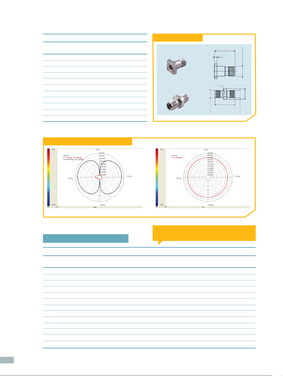
Electrical characteristics
Connector type & interface
Part number SD
Type of antenna Sleeve dipole
Available frequencies 0.4 - 9 GHz
Gain variation over azimuth <± 0.1 dB
Peak directivity 2.1 dBi (Typ)
Peak gain 1.8 dBi (Typ)
(1)
Effi ciency
VSWR
Return loss
90% (Typ)
(1)
1.2:1
(1)
< -20 dB
Cross polar level < 30 dB
Impedance 50 Ohms
Frequency BW (Ret. Loss < -15 dB) 10% (Typ)
(1) at the labeled center frequency
SD Typical elevation and azimuth radiation pattern
Type 23 PC35-50-0-51/199 UE
Huber+Suhner 31
PC35-50-0-1/199UE
1.6
(.063)
SW 8
(.315 AF.)
1/4-36 UNS-2A
13.3
(.524)
16.8
(.661)
1/4-36 UNS-2A
ø9
(.354 DIA)
1/4-36 UNS-2A
16
“A” = Total length “C” = Connector length
“B” = Phase center position “D” = Diameter
1/Low frequency dipole family
Mechanical characteristics
Part number Frequency range [MHz] A mm B mm C mm D mm Connector Type Weight
1
SD 390 380-410 546.8 378.8 8.2 33 PC 3.5 Female
SD 433 410-450 503.7 344.3 8.2 33 PC 3.5 Female1 600 g (approx)
SD 450 435-470 472.1 326.3 8.2 33 PC 3.5 Female1 600 g (approx)
SD 473 450-500 459.8 321.3 8.2 33 PC 3.5 Female1 600 g (approx)
SD 530 500-560 383.8 260.7 8.2 33 PC 3.5 Female1 500 g (approx)
SD 590 560-625 343.2 232.6 8.2 33 PC 3.5 Female1 450 g (approx)
SD 665 625-700 306.6 207.8 8.2 33 PC 3.5 Female1 400 g (approx)
SD 740 690-800 272.2 185.1 8.2 33 PC 3.5 Female1 400 g (approx)
SD 836 810-875 266.7 186.2 8.2 19 PC 3.5 Female1 150 g (approx)
SD 850 820-890 265.8 185.9 8.2 19 PC 3.5 Female1 150 g (approx)
SD 880 850-920 249.8 172.9 8.2 19 PC 3.5 Female1 150 g (approx)
SD 900 865-930 245.2 170.2 8.2 19 PC 3.5 Female1 150 g (approx)
SD 945 910-980 233.5 161.5 8.2 19 PC 3.5 Female1 150 g (approx)
(1) Huber+Suhner type 23 PC35-50-0-51/199UE
700 g (approx)
Page 3

Mechanical drawing
“A”
“D”
2/Medium frequency dipole family
“B” “C”
“A” = Total length “C” = Connector length
“B” = Phase center position “D” = Diameter
Mechanical characteristics
Part number Frequency range A mm B mm C mm D mm Connector Type Weight
SD 1230 1165 – 1295 MHz 178.7 123.2 9.8 15 PC 3.5 Female
SD 1450 1390 – 1540 MHz 156.1 109.0 9.8 15 PC 3.5 Female1 75 g (approx)
SD 1575 1500 – 1630 MHz 148.6 105.2 9.8 15 PC 3.5 Female1 75 g (approx)
SD 1730 1640 – 1830 MHz 132.7 93.2 9.8 15 PC 3.5 Female1 75 g (approx)
SD 1800 1710 – 1930 MHz 131.4 93.2 9.8 15 PC 3.5 Female1 75 g (approx)
SD 1900 1810 – 2030 MHz 129.7 93.2 9.8 15 PC 3.5 Female1 75 g (approx)
SD 2050 1910 – 2170 MHz 127.9 93.2 9.8 15 PC 3.5 Female1 75 g (approx)
SD 2140 1990 – 2330 MHz 126.7 93.2 9.8 15 PC 3.5 Female1 75 g (approx)
SD 2450 2330 – 2650 MHz 122.3 93.2 9.8 15 PC 3.5 Female1 75 g (approx)
SD 2600 2380 – 2950 MHz 121.4 93.2 9.8 15 PC 3.5 Female1 60 g (approx)
(1) Huber+Suhner type 31 PC35-50-0-1/199UE
1
75 g (approx)
Mechanical drawing
“A”
“B”
“D”
3/High frequency dipole family
“A” = Total length “C” = Connector length
“B” = Phase center position “D” = Diameter
“C”
Mechanical characteristics
Part number Frequency range A mm B mm C mm D mm Connector Type Weight
1
SD 3150-A 3000 – 3300 MHz 175.8 156 8.2 14 PC 3.5 Female
SD 3600-A 3450 – 3800 MHz 172.1 156 8.2 14 PC 3.5 Female1 90 g (approx)
SD 4000-A 3800 – 4200 MHz 171.6 156 8.2 14 PC 3.5 Female1 90 g (approx)
SD 5150-A 4900 – 5400 MHz 170.1 156 8.2 14 PC 3.5 Female1 90 g (approx)
SD 5650-A 5400 – 5900 MHz 168.2 156 8.2 14 PC 3.5 Female1 90 g (approx)
(1) Type 23 PC35-50-0-51/199 UE
Mechanical drawing
90 g (approx)
> Measurement antennas
“D”
“A”
“B”
“C”
17
 Loading...