

Page 1

MEASUREMENT PROBES
>
Dual Polarized Probes
Typical 3D pattern
SP 2600
SP 800
MEASUREMENT PROBES
> Main use:
• Spherical and planar near-fi eld measurement probes
• Measurement probes for far-fi eld systems
> Delivered documents:
• Typical performance data (TYMEDATM)
• Return loss data and port-to-port coupling
> Surface treatment:
• Alodine 1200 according to MIL-C 5541 E class 3
• Blue paint
> Optional equipment:
• Custom mechanical interface
• Absorder plates
> Related services:
• Calibration, maintenance, customization
➊ TECHNICAL PERFORMANCE
• Pattern shape
• On-axis polarization purity
• Off-axis polarization purity
• Low return loss / VSWR
• Port-to-port isolation
➋ DESIGN
• Consists of an orthomode junction (OMJ) feeding
a circular, open-ended or corrugated aperture
• OMJ based on a quad-ridge circular waveguide
with external feeding circuits
• OMJ feeds directly into a circular waveguide
providing wideband performance
• Electrical symmetry for mono-mode excitation
enforced by balanced feeding on a 1:3
bandwidth
➌ REPEATABILITY
• Stiff and robust mechanical design
• Precision machined
• High reliability connectors
• High reliability of external components
> Measurement antennas
47
Page 2
Standard probes
Electrical characteristics
Part number SP 800 SP 2600 SP 6000 SP 18000
Type of antenna dual probe dual probe dual probe dual probe
Frequency BW 0.8 – 3 GHz 2.6 – 8.2 GHz 6 – 20 GHz 18 – 40 GHz
Return loss < -10 dB < -10 dB < -10 dB < -10 dB
VSWR < 1.9 < 1.9 < 1.9 < 1.9
Polarization Dual Linear H & V Dual Linear H & V Dual Linear H & V Dual Linear H & V
Antenna gain > 8 dBi > 8 dBi > 7 dBi > 8 dBi
On-axis XPD > 45 dB > 45 dB > 45 dB > 45 dB
Impedance 50 Ohms 50 Ohms 50 Ohms 50 Ohms
Port-to-port isolation > 45 dB > 45 dB > 45 dB > 45 dB
Polarization orientation < 0.6° < 0.6° < 0.6° < 0.6°
Channel imbalance < 0.5 dB < 0.5 dB < 0.5 dB < 0.5 dB
(1)
Antenna losses
(1) Antenna Losses: Directivity – IEEE gain
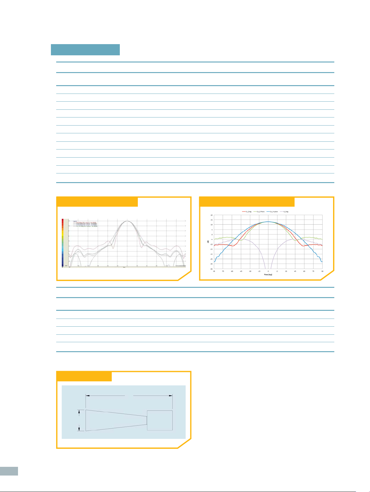
SP 800 directivity pattern at 2 GHz SP 6000 directivity pattern cuts at 12 GHz
< 1 dB < 1 dB < 1.5 dB < 2 dB
48
Mechanical characteristics
Part number SP 800 SP 2600 SP 6000 SP 18000
Length (L) < 800 mm < 500 mm < 365 mm < 235 mm
Radiating aperture diameter (D) 280 mm 120 mm 50 mm 17 mm
Weight < 5 Kg < 2.5 Kg < 2 Kg < 1.9 Kg
Interface Standard 110 Standard 110 Standard 110 Standard 110
Connectors PC 3.5 Female K Female
(1) SWMI type 1032-10SF
Mechanical drawing
“L”
“D”
(1)
K Female
(1)
K Female
(1)
Page 3

Custom probes
Probe customization can be implemented
for the following features:
Polarization:
• Dual Linear
• Dual Circular
Aperture types:
• Corrugated design based on
customer specifi cations
• Flared design
• Stepped design
• Open ended design
Launcher types:
• Auto balanced feeding
• SP feeding (refer to standard probes)
• Balanced feeding with external BFN
• Waveguide orthomode junction
Examples of custom probes are shown below.
DCP580
DLP: Dual Linear Probe DCP: Dual Circular Probe
Probe Frequency range Launcher type Aperture
DCP-SC-100
DLP-SC-100
DLP-AC-150 1.50 – 1.90 GHz Auto balanced feeding Corrugated
DCP-SC-200
DLP-SC-200
DLP-AC-190 1.90 – 2.35 GHz Auto balanced feeding Corrugated
DLP-AC-235 2.35 – 2.90 GHz Auto balanced feeding Corrugated
DLP-AF-270 2.70 – 3.40 GHz Auto balanced feeding Flared
DLP-BC-340
DCP-BC-340
DLP-SS-340 3.40 – 7.00 GHz SP feeding Stepped-Flared
DLP-AC-390 3.90 – 4.85 GHz Auto balanced feeding Corrugated
DLP-BC-580 5.80 – 6.70 GHz External BFN Corrugated
DCP-SC-580 5.80 – 6.80 GHz SP feeding Corrugated
DLP-AC-610 6.10 – 7.50 GHz Auto balanced feeding Corrugated
DCP-SC-600
DLP-SC-600
DCP-SC-700
DLP-SC-700
DLP-AF-850 8.50 – 10.00 GHz Auto balanced feeding Flared
DCP-SC-1000
DLP-SC-1000
DLP-WC-1070 10.70 – 14.60 GHz Waveguide junction Corrugated
DCP-SC-1240
DLP-SC-1240
DLP-WC-1670 16.70 – 18.60 GHz Waveguide junction Corrugated
1.00 – 2.00 GHz SP feeding Corrugated
2.00 – 3.30 GHz SP feeding Corrugated
3.40 – 4.20 GHz External BFN Corrugated
6.00 – 12.00 GHz SP feeding Corrugated
7.00 – 14.00 GHz SP feeding Corrugated
10.00 – 20.00 GHz SP feeding Corrugated
12.40 – 20.00 GHz SP feeding Corrugated
> Measurement antennas
49
 Loading...