

Page 1
MEDIUM & HEAVY DUTYDBDR SERIES
>
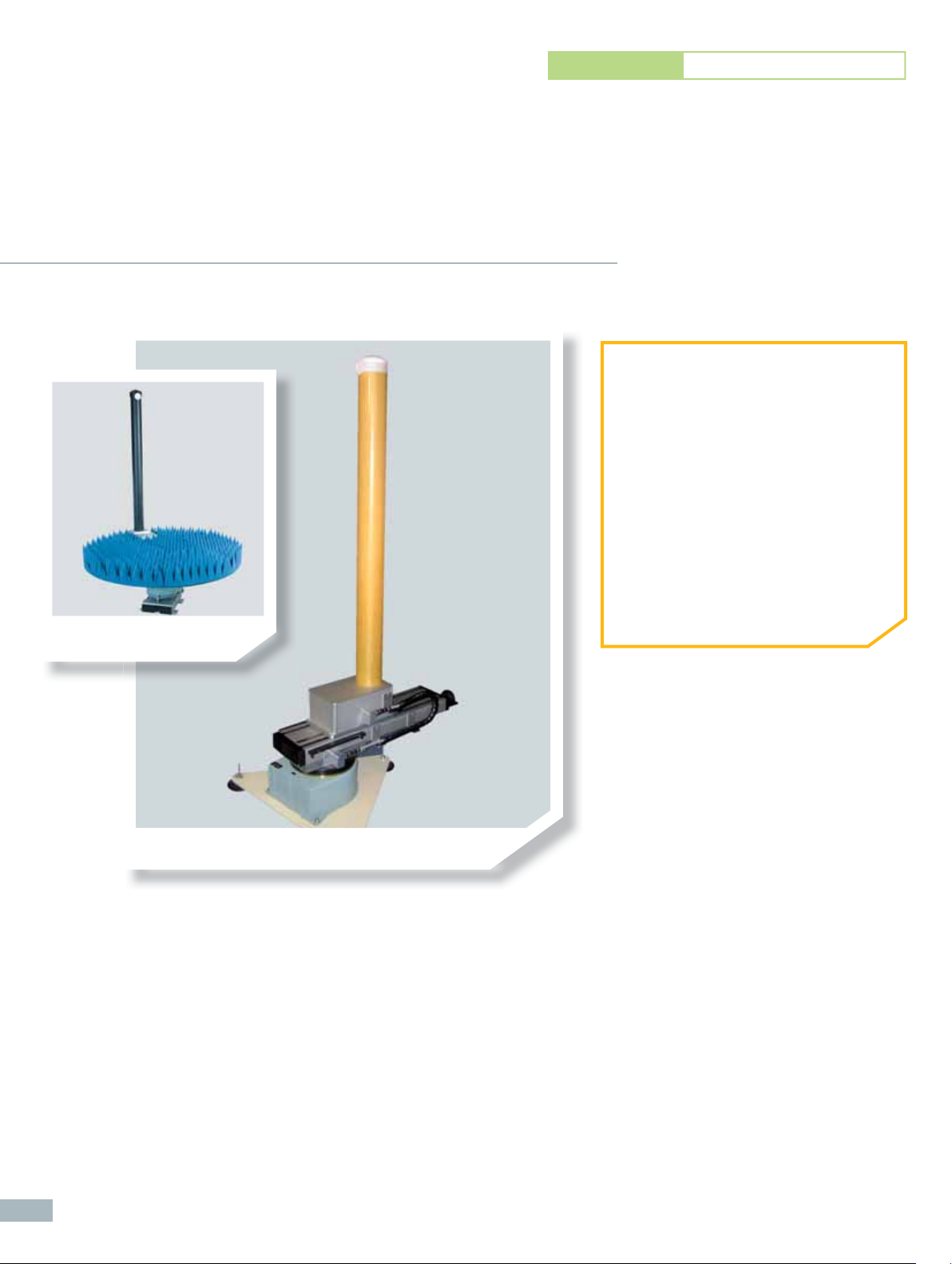
Model Towers – DBDR:
Dielectric Belt-Driven,
Medium & Heavy Duty
DBDR-MD Shown with absorber
platter (Opt. 003)
➊ APPLICATIONS
• Medium-directivity Antenna Testing
• Far-Field or Spherical Near-Field
Applications
• Indoor Use
➋ PRODUCT HIGHTLIGHTS
• Low Electromagnetic Profi le for Small
Broad-Beam Antennas
• Interchangeable AUT Foam Bracket –
See Options Table
• Compatible with Rotary Positioners
(Support Wiring Required)
128
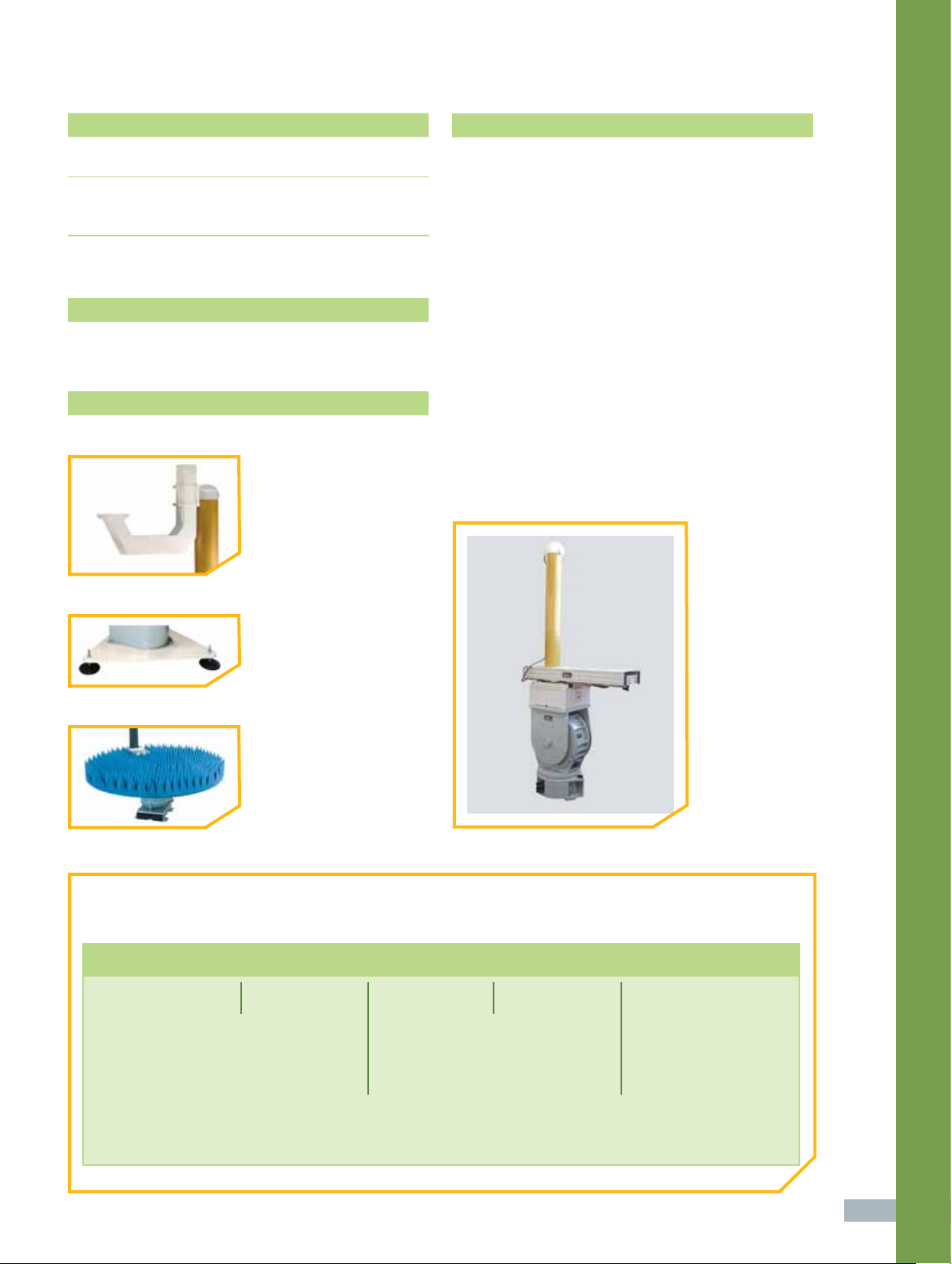
DBDR-MD Shown with lower positioner and triangular base plate
(Opt. 002)
The Dielectric Belt Driven Rotator (DBDR) model tower series is a lower-scattering alternative to
conventional metal towers with a roll axis. They are generally used for omni-directional antenna
measurements and are available in two capacity categories: medium and heavy duty.
The primary components include an integrated gearhead roll positioner, mast and a manual linear offset slide, which allows users to position the AUT’s phase center over the lower
azimuth axis. The base plate of the DBDR assembly provides a convenient interface to
the specifi ed lower positioner. The DBDR series is available in either encoder or synchro
format. Typical axis geometry confi gurations include Roll/AZ.
Page 2
supplied accessories
technical notes
>
CD-ROM Documentation Set:
User Manual (Installation, Setup, Operation & Maintenance)
>
Cables:
Cable Carrier
Interconnect Cable for Connection to Lower Positioner
optional accessories
Lower Positioner
options
Option 001
Option 002
• Foam Bracket w/ Interface
Plate, Up to 4.4 lbs (2 kg)
• Portable Triangular Base Plate
(Increases Overall Height)
1 Model tower height is defi ned as the distance from
the base of the offset slide to the center of the roll axis.
2 The lower positioner may require electrical wiring and/
or an RF path to support the model tower. Options are
available for the lower positioner, including EX002, SR,
and RJ. Lower positioner purchased separately.
3 All accuracy data is based on no-load conditions.
Contact ORBIT/FR for accuracy under load conditions.
4 Roll axis is equipped with adjustable limit switches
capable of approx 20° to 900° total travel. When rotary
joint options are specifi ed, limit switches remain but
are electrically disabled. Roll axis is factory-set at 400°
(± 200°).
5 Rotary joint options may alter the original physical
profi le of the roll axis stage. Consult ORBIT/FR.
6 Verify model tower’s maximum swing radius
(G - clearance to absorber) when specifying this
product for use inside an anechoic chamber.
7 Dimensions may vary depending on fi nal confi guration.
Option 003
• Absorber Platter
ORDERING INFORMATION
• Build your confi guration using the ordering example below.
DBDR MD 21 60
---
Basic Model
Tower Series
Capacity:
MD - Medium
HD - Heavy
> Model Towers
Linear Offset
Slide Travel (in)
Total Roll-to-Base
Height (in or mm)
129
Page 3

Specifi cations - DBDR Series Model Towers Medium and Heavy Duty
Model
Parameter Units
DBDR-MD DBDR-HD
Technical Notes
Model Tower Assembly
1, 2, 3, 4, 5, 6, 7 1, 2, 3, 4, 5, 6, 7
Total Model Tower Height (F) (maximum)
Fore-Aft Bending Moment (maximum)
6
Maximum Swing Radius
Weight (Approx.)
1. Roll Positioner (Integrated Gearhead)
Operating Load
Delivered Torque
Withstand Torque
Gearhead Turntable Bending Moment (maximum)
Motor Drive Power
Nominal Speed
Standard Angle Transducer Format
Standard Accuracy
Gearhead Flange Diameter
(H)
ft 7 7
m 2.1 2.1
ft-lbs 32 110
m-kg 4.4 15.2
in 39 43
mm 1,000 1,100
lb 130 160
kg 59 73
lb 26 110
kg 12 50
ft-lbs 10 20
m-kg 1.4 2.8
ft-lbs 15 30
m-kg 2 4
ft-lbs 28 108
m-kg 4 15
hp 1/20 1/20
rpm 6 2
Dual Speed
Synchro
deg ± 0.1 ± 0.1
in 3.03 4.72
mm 70 120
Dual Speed
Synchro
130
2. Mast
Mast Style
Mast Construction
3. Linear Offset Slide
Limit-to-Limit Travel (A)
Slide Construction
Straight Straight
Aramid/Resin
Composite
in 21 21
mm 533 533
Aluminum Aluminum
Aramid/Resin
Composite
Page 4

Specifi cations - DBDR Series Model Towers Medium and Heavy Duty
Model
Parameter Units
DBDR-MD DBDR-HD
4. Lower Positioner
Lower Positioner
2
Environmental
Operating Temperature
Options*
EN001
EN004
RJ
MM Mounting Thread
(*) See Options Glossary on page 132
(-) N/A S Standard Opt Optional
Incremental Encoder (Standard Accuracy)
Accuracy
Absolute Encoder (Standard Accuracy)
Accuracy
4,5
Rotary Joint
Refer to AZ, AZ/EL, EL/AZ
or AZ/EL/AZ catalog section
- 4° F to 140° F (- 20° C to 60° C)
Opt Opt
deg ± 0.1 ± 0.1
Opt Opt
deg ± 0.1 ± 0.1
RJ12L
RJ18L
RJ40L
RJ50L
MM002
MM003
RJ12L
RJ18L
RJ40L
RJ50L
MM002
MM003
> Model Towers
131
 Loading...