

LEGACY SERIES AZ/EL/AZ
MEDIUM DUTY
>
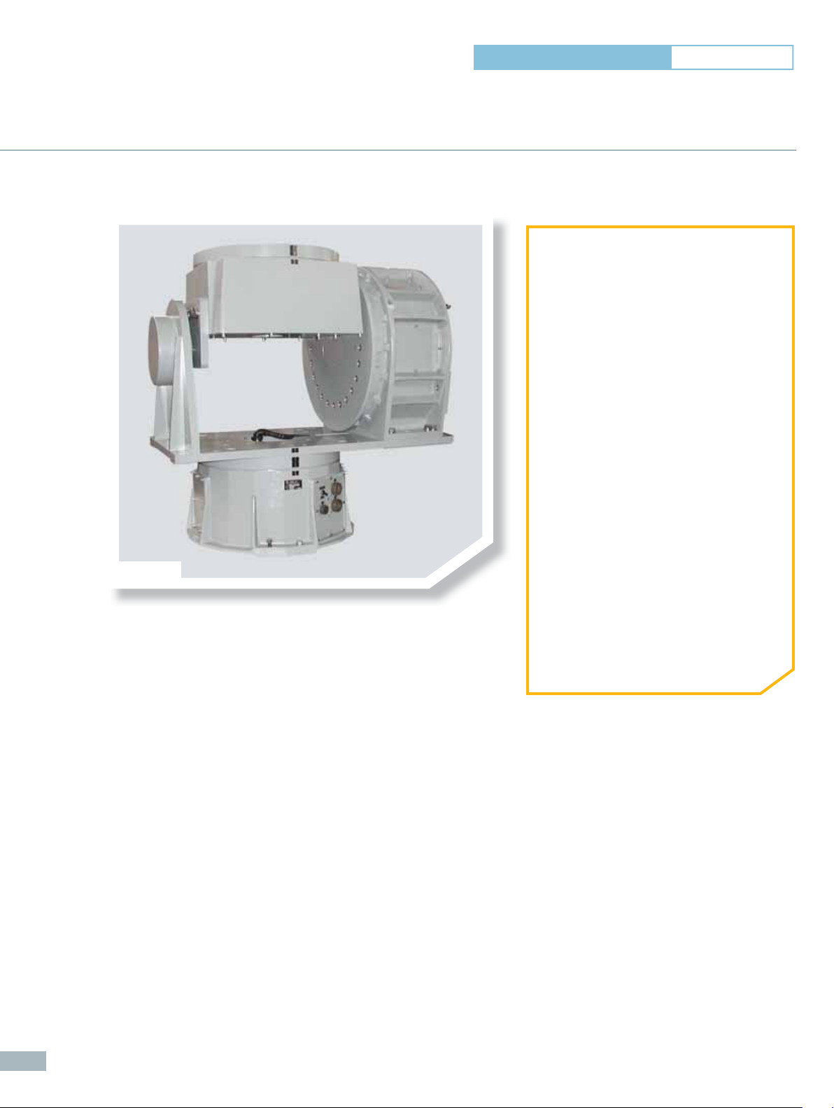
AL-4572-1
AZ/EL/AZ Positioners – Medium Duty
AL- 4569-1 • AL- 4570-1 • AL- 4571-1 • AL- 4572-1 • AL- 4573-1 • AL- 4574-1 • AL- 4575-1
➊ APPLICATIONS
• General Purpose Positioning
Subsystems
• Far-Field & Near-Field Antenna
Measurements
• Indoor & Outdoor Use
➋ PRODUCT HIGHTLIGHTS
• Broad Selection – 7 Models
• Vertical Loads Ranging from 100 to
10,000 lbs (45 to 4,540 kg)
• Turntable Diameters Ranging from
10.3 to 24.1 in (262 to 612 mm)
• Excellent Angular Position Accuracy
• Low Backlash Design
• Precision Bearings
• Closed Loop Servo Control
• Industry-Standard Wiring
• Tachometers for Optimum Speed
Regulation & Control
• Wide Operating Temperature Range:
- 4° F to 140° F (- 20° C to 60° C)
• Fully Enclosed Design of Drive Gear
Train & Data Take-Off
• Wide Variety of Available Options
72
Our Legacy Series AZ/EL/AZ positioners provide
accurate rotation, velocity, and direction for customers
involved in antenna design and development.
Their rugged yet simple construction ensures maximum
reliability and trouble-free operation, yielding the best
size and weight versus performance ratio.
Typically, the primary components include the body, precise slew bearings, DC motors, gear reducers,
synchro assemblies, and limit switch assemblies. The turntable surface is designed with a threaded
mounting hole pattern for customer use. A Safe/Operate switch is included to ensure the safety
of working personnel.
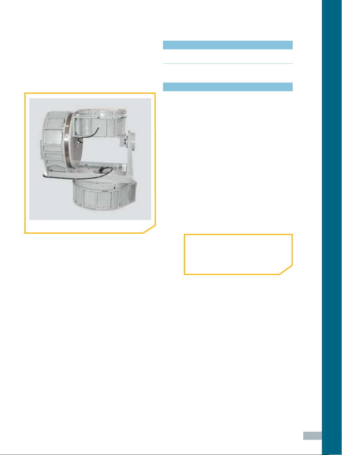
❚ AL- 4575-1
supplied accessories
>
CD-ROM Documentation Set:
User Manual (Installation, Setup, Operation & Maintenance)
technical notes
1 All accuracy data is based on no-load conditions.
Contact ORBIT/FR for accuracy under load conditions.
2 All models are equipped with adjustable limit switches
capable of approx 20° to 900° total travel. When rotary
joint and slip ring options are specifi ed, limit switches
remain but are electrically disabled.
Multi-axis positioners are factory-set at:
• Upper Azimuth Axis: 400° (± 200°)
• Elevation Axis: 190° (± 95°)
• Lower Azimuth Axis: 400° (± 200°)
3 Slip Ring & Rotary Joint Option Notes:
• Certain slip ring options may require an extension
cap that protrudes above the turntable surface.
Positioner height may increase. Consult ORBIT/FR.
• Slip ring contacts for customer use are provided
with dedicated connectors.
• When rotary joint and/or slip ring options are
specifi ed, no central thru-hole is available to the
user. Option TH002 and TH003 are available in
lieu of rotary joint and/or slip ring options.
ORDERING INFORMATION
• Refer to Legacy Series AZ/EL/AZ
Positioners – Medium Duty Specifi cation
Table
> Rotary Positioners
73

Specifi cations - Legacy Series AZ/EL/AZ Positioners Medium Duty
Positioner Model
Parameter Units
AL-4569-1 AL-4570-1 AL-4571-1 AL-4572-1 AL-4573-1 AL-4574-1 AL-4575-1
Outline Dimension Drawing Number
Technical Notes
Operational
10-2034 10-2035 10-0651 09-0965 11-2710 09-0966 10-2037
1, 2, 3 1, 2, 3 1, 2, 3 1, 2, 3 1, 2, 3 1, 2, 3 1, 2, 3
Bending Moment
Vertical Load
Upper Azimuth
Delivered Torque
Withstand Torque
Drive Power
Nominal Speed
Standard Angle
Transducer Format
Standard
Accuracy
Maximum
Backlash
Elevation Limit-to-Limit Travel
Elevation
Lower Azimuth
Upper Azimuth
Elevation
Lower Azimuth
Upper Azimuth
Elevation
Lower Azimuth
Upper Azimuth
Elevation
Lower Azimuth
Upper Azimuth
Elevation
Lower Azimuth
Upper Azimuth
Elevation
Lower Azimuth
ft-lbs 120 210 600 2,000 4,200 7,500 12,000
kg-m 20 30 80 280 580 1,040 1,660
lbs 100 200 800 1,250 2,800 5,000 10,000
kg 45 90 360 570 1,270 2,270 4,540
ft-lbs 90 150 150 500 500 500 1,200
kg-m 12 20 20 70 70 70 170
ft-lbs 90 150 500 1,200 2,800 5,000 10,000
kg-m 12 20 70 170 390 690 1,380
ft-lbs 90 150 500 500 1,200 1,200 2,800
kg-m 12 20 70 70 170 170 390
ft-lbs 120 210 210 600 600 600 2,000
kg-m 20 30 30 80 80 80 280
ft-lbs 120 210 600 2,000 4,200 7,500 12,000
kg-m 20 30 80 280 580 1,040 1,660
ft-lbs 120 210 600 600 2,000 2,000 4,200
kg-m 20 30 80 80 280 280 580
hp 1/8 1/8 1/3 1/3 1/3 3/4 3/4
hp 1/8 1/8 1/3 3/4 3/4 3/4 3/4
hp 1/8 1/8 1/3 1/3 3/4 3/4 3/4
rpm 2.6 2 2 1.5 1.5 1.5 1.3
deg/min 900 720 540 470 180 108 55
rpm 3 2 1.5 1.5 1.3 1.3 0.5
deg ± 0.04 ± 0.03 ± 0.03 ± 0.03 ± 0.03 ± 0.03 ± 0.03
deg ± 0.04 ± 0.04 ± 0.03 ± 0.03 ± 0.03 ± 0.03 ± 0.03
deg ± 0.04 ± 0.03 ± 0.03 ± 0.03 ± 0.03 ± 0.03 ± 0.03
deg 0.08 0.06 0.06 0.05 0.05 0.05 0.05
deg 0.08 0.06 0.06 0.05 0.05 0.05 0.05
deg 0.08 0.06 0.06 0.05 0.05 0.05 0.05
deg ± 95 ± 95 ± 95 ± 95 ± 95 ± 95 ± 95
Dual Speed
Synchro
Dual Speed
Synchro
Dual Speed
Synchro
Dual Speed
Synchro
Dual Speed
Synchro
Dual Speed
Synchro
Dual Speed
Synchro
74
Physical
Height at 0° Elevation
Weight
Turntable Diameter
Lower Azimuth Moment Bearing
Capacity (Static)
Environmental
Operating Temperature
in 20.3 23.8 30.4 39.3 46.9 46.9 48.0
mm 516 605 772 997 1,190 1,190 1,219
lbs 155 280 420 820 1,200 1,232 1,600
kg 70 127 191 372 544 559 726
in 10.3 12.5 12.5 20.3 20.3 20.3 24.1
mm 262 318 318 516 516 516 612
ft-lbs 300 800 3,000 10,000 22,000 22,000 30,000
kg-m 42 111 415 1,383 3,042 3,042 4,148
- 4° F to 140° F (- 20° C to 60° C)

Options*
Positioner Model
Parameter Units
AL-4569-1 AL-4570-1 AL-4571-1 AL-4572-1 AL-4573-1 AL-4574-1 AL-4575-1
Incremental Encoder
(Standard Accuracy)
Accuracy – Upper Azimuth
EN001
Accuracy – Elevation
Accuracy – Lower Azimuth
Direct Incremental Encoder
(High Accuracy)
Accuracy – Upper Azimuth
EN002
Accuracy – Elevation
Accuracy – Lower Azimuth
Direct Absolute Encoder
(High Accuracy)
Accuracy – Upper Azimuth
EN003
Accuracy – Elevation
Accuracy – Lower Azimuth
Absolute Encoder
(Standard Accuracy)
Upper Azimuth
EN004
Elevation
Lower Azimuth
SR Slip Ring
RJ Rotary Joint
TH
EX Internal Harnessing
CF Connector Format
LS Leveling Screw (set)
ST Stow Lock
MM Mounting Thread
IC Interlock Circuit
*See Options Glossary on page 132 (-) N/A Opt Optional
3
3
Central Thru-Hole Inner
Diameter
Opt Opt Opt Opt Opt Opt Opt
deg ± 0.04 ± 0.03 ± 0.03 ± 0.03 ± 0.03 ± 0.03 ± 0.03
deg ± 0.04 ± 0.04 ± 0.03 ± 0.03 ± 0.03 ± 0.03 ± 0.03
deg ± 0.04 ± 0.03 ± 0.03 ± 0.03 ± 0.03 ± 0.03 ± 0.03
Opt Opt Opt Opt Opt Opt Opt
deg ± 0.005 ± 0.005 ± 0.005 ± 0.005 ± 0.005 ± 0.005 ± 0.005
deg ± 0.005 ± 0.005 ± 0.005 ± 0.005 ± 0.005 ± 0.005 ± 0.005
deg ± 0.005 ± 0.005 ± 0.005 ± 0.005 ± 0.005 ± 0.005 ± 0.005
Opt Opt Opt Opt Opt Opt Opt
deg ± 0.005 ± 0.005 ± 0.005 ± 0.005 ± 0.005 ± 0.005 ± 0.005
deg ± 0.005 ± 0.005 ± 0.005 ± 0.005 ± 0.005 ± 0.005 ± 0.005
deg ± 0.005 ± 0.005 ± 0.005 ± 0.005 ± 0.005 ± 0.005 ± 0.005
Opt Opt Opt Opt Opt Opt Opt
deg ± 0.04 ± 0.03 ± 0.03 ± 0.03 ± 0.03 ± 0.03 ± 0.03
deg ± 0.04 ± 0.04 ± 0.03 ± 0.03 ± 0.03 ± 0.03 ± 0.03
deg ± 0.04 ± 0.03 ± 0.03 ± 0.03 ± 0.03 ± 0.03 ± 0.03
SR051U
SR101U
RJ12U
RJ18U
RJ26U
RJ40U
RJ50U
RJ12L
RJ18L
RJ26L
RJ40L
RJ50L
in 2.5 2.5 2.5 3.0 3.0 3.0 3.0
mm 63 63 63 76 76 76 76
EX002 EX002 EX002 EX002 EX002 EX002 EX002
-- - - - - -
TH002
TH003
- - Built-In Built-In LS001-3 LS001-3 LS001-6
------MM002
MM003
IC001 IC001 IC001 IC001 IC001 IC001 IC001
SR051U
SR101U
SR201U
SR301L
RJ12U
RJ18U
RJ26U
RJ40U
RJ50U
RJ12L
RJ18L
RJ26L
RJ40L
RJ50L
TH002
TH003
MM002
MM003
SR051U
SR101U
SR201U
SR301L
RJ12U
RJ18U
RJ26U
RJ40U
RJ50U
RJ12L
RJ18L
RJ26L
RJ40L
RJ50L
TH002
TH003
MM002
MM003
SR051L
SR101U
SR201U
SR301U
SR402L
RJ12U
RJ18U
RJ26U
RJ40U
RJ50U
RJ12L
RJ18L
RJ26L
RJ40L
RJ50L
TH002
TH003
MM002
MM003
SR051U
SR101U
SR201U
SR301U
SR402L
RJ12U
RJ18U
RJ26U
RJ40U
RJ50U
RJ12L
RJ18L
RJ26L
RJ40L
RJ50L
TH002
TH003
MM002
MM003
SR051U
SR101U
SR201U
SR301U
SR402L
SR502L
RJ12U
RJ18U
RJ26U
RJ40U
RJ50U
RJ12L
RJ18L
RJ26L
RJ40L
RJ50L
TH002
TH003
MM002
MM003
SR051U
SR101U
SR201U
SR301U
SR402L
SR502L
RJ12U
RJ18U
RJ26U
RJ40U
RJ50U
RJ12L
RJ18L
RJ26L
RJ40L
RJ50L
TH002
TH003
MM002
MM003
> Rotary Positioners
75
 Loading...