

Page 1
AL-48060 SERIES
>
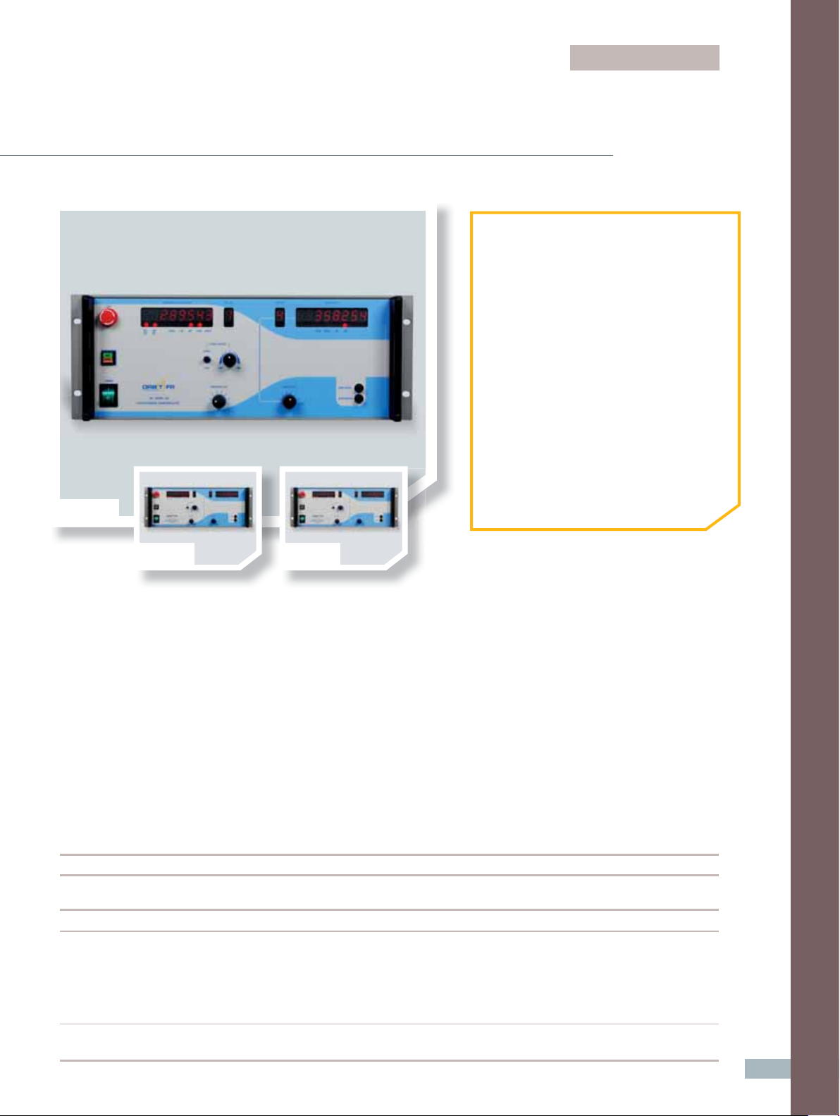
AL-48061
Positioner Controller, Sequential
➊ APPLICATIONS
• Antenna Test Automation
• Encoder or Synchro-Based Positioners
• Medium & Heavy Duty Positioning
Subsystems
➋ PRODUCT HIGHTLIGHTS
• Sequential Control Up to 6 Axes
• Dynamic Density Control (DDC)
• Selectable PIV & PID Control Loop
• Motion Profi les
• Audible Limit Alarm
• Digital Synchro Alignment
• Programmable Trigger Pulse Width
• Setup Utility Software
• Self-Diagnostics
AL-48062 AL-48063
This popular series of high performance, easy-to-operate, programmable six axis positioner
controllers provide manual front panel or remote control of rotary and linear positioners
manufactured by ORBIT/FR (or equivalent third party positioners that incorporate shunt wound
or permanent magnet brush DC motors, 50/60/400 Hz synchros, or encoders).
Optional interfaces are available for position transducers such as absolute encoders, Inductosyn
®
,
and inclinometers. The AL-48060 series controllers can be purchased in three confi gurations.
AL-48060’s digital servo loop provides advanced remote and local control while maintaining a simple human
interface for manual operation. Position transducer and velocity type can be individually confi gured for each
axis. These units are capable of driving a total of six axes sequentially, one axis at a time.
Series Overview
Model AL-48061 AL-48062 AL-48063
Formerly AL-4806-3C Formerly AL-4806-3C Opt.1 Formerly AL-4806-3C Opt. 1 V2
Horsepower PCU-Dependent 1 2
PCU Requires Separate PCU Built-In Built-In
Compatible With:
- AL-4146-2
- AL-4147-2
- AL-4106-2-6A
- AL-4107-2-6A
Notes Requires purchase of 910074-01 - -
control cable
(-) N/A
> Positioner Controllers, PCUs & LCUs
9
Page 2

front panel
supplied accessories
>
Controls:
AC Power On/Off
Axis Select
- Operating Axis
- Display Axis
Direction/Speed
- Coarse & Fine
Position Offset
Position Zero
Remote/Local Control (BUS/PANEL)
Emergency Stop (E-Stop)
>
Displays & Indicators:
Axis Position
- Operating Axis
- Display Axis
Axis Number
- Operating Axis
- Display Axis
Limit Indicators
User-Selectable Scales: ± 180°, 0°-360°, Linear
Remote/Local
Speed (Operating Axis)
technical notes
AL-48061 and AL-48062 are functionally compatible with
previous generation models AL-4806-3A & AL-4806-3A
Opt. 1, respectively, with limitations and enhancements
(consult your local factory sales representative for
specifi c compatibility needs).
>
CD-ROM Documentation Set:
User Manual (Installation, Setup, Operation)
Programming Reference Manual
Software Setup Utility
>
Cables:
Cable, CAN, DB9 to RJ45 (for Setup Utility)
Cable, RS-232, DB9 to RJ45 (for Setup Utility)
AC Power Cord, IEC-320 (F) to Plug
options
Opt. 003 - Inductosyn® Interface
Opt. 004 - Inclinometer Interface
Opt. 005 - EnDat® Absolute Optical Encoder
Interface
Opt. 007 - 400 Hz Synchro Support
(Includes External 400 Hz Generator)
Opt. 008 - 11.8 Volt Synchro Input
(Requires Opt. 007)
Opt. 009 - Correction Table Capability
(On-site error mapping purchased separately)
Opt. 101 - Additional Manual Set
Opt. 102 - International Localization
(Specify Country & Voltage)
Optional Standard
position sensors
>
Axis-Independent Position Sensor Selection:
Single-Speed, Dual-Speed Synchro & Incremental Encoder
Absolute Encoder (EnDat®), Inclinometer & Inductosyn®
(Refer to Options List)
communication & i/o
IEEE-488.2 Compatible
RS-232 (RJ45)
TTL Position Increment
BCD/Binary Position Output
ORDERING INFORMATION
• AL-48061 Positioner Controller, 6 Axis
• AL-48062 Positioner Controller,
6 Axis w/Built-In PCU, 1 HP
• AL-48063 Positioner Controller,
6 Axis w/Built-In PCU, 2 HP
10
Page 3

Specifi cations - AL-48060 Series Sequential Controllers
Model AL-48061 AL-48062 AL-48063
Operational
• AC Power On/Off
• Local/Remote (Panel/Bus)
• Axis Select
• Coarse/Fine Speed
Front Panel Controls
& Indicators
• Speed/Direction Control
• Emergency Stop (Latching Panic Button)
• Dual 7-Segment LED Position Display
• Velocity Display
• Limit, Scale & LCU/Remote Indicators
• Position Offset Entry
Correction Table Support
(Geometrical Error)
Electrical
AC Input Power
Power Dissipation
Controlled Axes
EMI Filtering
VDE Tests
Speed Control Range
Tachometer Input Voltage
BCD/Binary Output
Optional (Opt. 009)
• 115/230 VAC +/- 10%, 47-63 Hz, single phase
• 7A rms @ 115 VAC
• 3.5A rms @ 230 VAC
1.5 KVA max
6 Sequential control
MIL-STD-461/2, VDE 0871/3.68
• Leakage: 1,500 VAC
• Insulation: 500 VDC
• Bonding: 25 ADC
• User-Selectable
• Coarse: 0-100%
• Fine: 0-18%
0 to +40 VDC
• BCD Update Rate: 24 Bit @ 61 µsec (± 10%)
• BINARY Update Rate: 19 Bit @ 80 µsec (± 10%)
• Software selectable output
• Compatible with AL-4806-3A, AL-4906-3A, FR8502
• Connector: 50 Pin D-type
> Positioner Controllers, PCUs & LCUs
TTL Increment Output
Supported Position Sensors
• Pulse Width: Selectable from 1.96 µsec to 248 µsec
• Pulse Logic (Polarity): Selectable
• Interval Resolution: 0.0001°
• Max Time Jitter: 10 µsec
• Max Increment Rate: 4000 pulses per second
• Connector: BNC (F)
• Supported Motion Modes: Sector, Raster
• Alternate Mode: TTL pulses at discrete positions
• Selectable for each axis via setup utility
• Dual Speed Synchro (1:1 & 36:1)
• Single Speed Synchro (1:1)
• Incremental Encoder
®
Absolute Optical Encoder (Opt.005)
• EnDat
• 400 Hz Synchro Support (90 v or 11.8 v) (Opt. 007)
• Inclinometer (Opt.004)
• Inductosyn® (Opt.003)
11
Page 4

Model AL-48061 AL-48062 AL-48063
Electrical
Data Take-Off Resolution
Dual Speed Synchro (1:1 & 36:1)
Single Speed Synchro (1:1)
Incremental Encoder
®
Absolute Encoder
EnDat
(Optional)
®
Inductosyn
(Optional)
Inclinometer (Optional)
Communication Links
0.0025° (12 bit) 0.0006° (14 bit)
0.087 (12 bit) 0.02 (14 bit)
Up to 29 bit resolution
Up to 29 bit resolution
- 4
2.8 x 10
deg
Selectable Range
• IEEE-488.2
• RS-232 (RJ45)
• CAN Bus (setup & confi guration utility only)
Supported Motion Control
Filters
Compatible Power Control Units
(PCU)
Load Inductance
Maximum Motor Size (Axes A-F)
Motor Armature Supply (Axes A-F)
Motor Armature Current
Limiting
Motor Field Supply
Motor Driver Method
Motor Direction
Dynamic Braking Supply
Compatible Local Control Units
(LCU)
Physical
PID/PIV
• AL-4146-2
• AL-4147-2
• AL-4106-2-6A
-
• AL-4107-2-6A
- No output choke required
- 1 HP 2 HP
- 0 to ± 110 VDC, up to 10 Amps 0 to ± 110 VDC, up to 15 Amps
• 2.5 to 10 Amps
-
• Each Axis Selectable Via Internal
Dip Switch
• 2.5 to 15 Amps
• Each Axis Selectable Via Internal
Dip Switch
- 110 VDC, 2 Amps Max Continuous
-
• Filtered Pulse Width Modulated (PWM)
• 32 kHz Nominal Switching Rate (above audible range)
- Bi-directional
- 24 VDC, 2 Amps Max
-
• AL-4146-2L Series
• AL-4188 Series
12
Dimensions
Weight
Environmental
Operating Temperature
Storage Temperature
Relative Humidity
(-) N/A
• 19.0 in (48.3 cm) Width
• 7.0 in (17.8 cm) Height
• 19.5 in (49.4 cm) Depth
40 lbs (18.2 kg) 60 lbs (27.2 kg)
32° to 122° F (0° to 50° C)
- 4° to 167° F (- 20° to 75° C)
90%
 Loading...