

Page 1
MEDIUM DUTYAL-48000 SERIES
>
Model Towers – Medium Duty
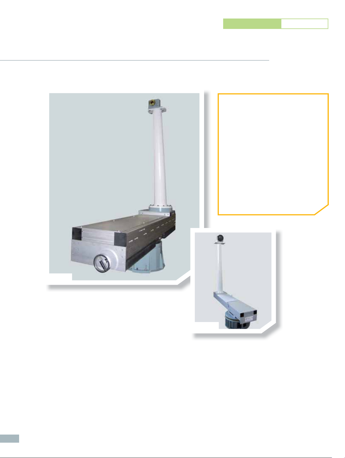
AL-48000 Series
➊ APPLICATIONS
• General Purpose Positioning
Subsystems
• Far-Field & Near-Field Antenna
Measurements
• Indoor Use
➋ PRODUCT HIGHTLIGHTS
• High Performance Torque & Accuracy
• Linear Bearings
• AUT Adjustment over Lower AZ Center
of Rotation
• Compatible with Standard Antenna
Positioners (Support Wiring Required)
120
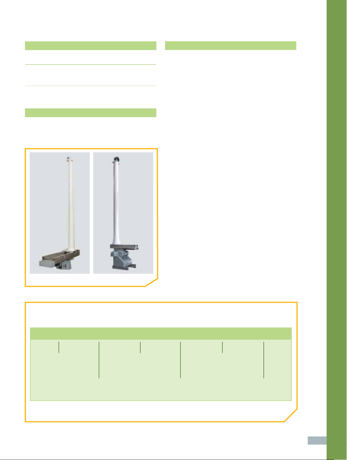
AL-48100
Our AL-48000 model towers are suited
to for medium duty applications with an
operating load of up to 1,000 lbs (455 kg).
This series is available with a choice of either
a manual handwheel style or motorized linear
offset slide. The mast, which can be vertical
or inclined, is available in either fi berglass
or aluminum construction.
AL-48200
Page 2
supplied accessories
technical notes
>
CD-ROM Documentation Set:
User Manual (Installation, Setup, Operation & Maintenance)
>
Cables:
Cable Carrier
Interconnect Cable for Connection to Lower Positioner
optional accessories
Absorber Plates
Alignment Fixture Between Roll Positioner & Mast
Counterweights (may apply if elevation axis is defi ned)
AL-48210 AL-48110
1 Model tower height is defi ned as the distance from
the base of the offset slide to the center of the roll axis.
The height of the model tower assembly will impact
pickup mode in lower positioners containing an
elevation axis. Defi ne elevation measurement angles
and verify lower positioner specifi cations when
confi guring this product.
2 The lower positioner may require electrical wiring
and/or an RF path to support the model tower.
Options are available for the lower positioner,
including EX002, SR, and RJ. Lower positioner
is purchased separately.
3 All accuracy data is based on no-load conditions.
Contact ORBIT/FR for accuracy under load conditions.
4 Roll axis is equipped with adjustable limit switches
capable of approx 20° up to 900° total travel. When
rotary joint options are specifi ed, limit switches remain
but are electrically disabled. Roll axis is factory-set at
400° (± 200°).
5 Rotary joint options may alter the original physical
profi le of the roll axis stage. Consult ORBIT/FR.
6 Verify model tower’s total swing radius (G - clearance
to absorber) when specifying this product for use
inside an anechoic chamber.
7 Dimensions may vary depending on fi nal confi guration.
8 Standard offset slide travel is 24 inches. Other lengths
are available in one foot increments, up to 8 feet.
9 For special requirements with space limitations,
the linear offset slide can be provided upside-down
in order to move the mast without moving the slide.
10 An optional alignment fi xture can be installed between
the roll axis positioner and mast, with or without a
base riser.
> Model Towers
ORDERING INFORMATION
• Build your confi guration using the ordering example below.
AL-48100 24 96 F C 560
Model Tower Series
481xx - Manual
482xx - Motorized
* To order with integrated gearhead, leave the end of the part number blank and add GH2 or GH3 as a separate line item.
For GH specs, refer to specifi cation table on page 122.
-- - - -
Total Roll-to-Base
Height (in)
Mast
C - Inclined
V - Vertical
Linear Offset
Slide Travel (in)
Mast Construction
(Fiberglass or Aluminum)
Discrete
Positioner Model*
121
Page 3

Specifi cations - AL-48000 Series Model Towers Medium Duty
Manual Motorized Manual Motorized
Parameter Units
AL-48100 AL-48200 AL-48110 AL-48210
Technical Notes
Model Tower Assembly
1, 2, 3, 4, 5, 6, 7, 8, 9, 10 1, 2, 3, 4, 5, 6, 7, 8, 9, 10
Model
Operating Load (maximum)
Total Model Tower Height (F) (maximum)
Fore-Aft Bending Moment (maximum)
6
Maximum Swing Radius
(H)
Weight (Approx.)
1. Roll Positioner
Maximum Roll Positioner
Discrete
Option 1:
Maximum Roll/EL Positioner
Positioner
Gearhead Model
Operating Load
Delivered Torque
Withstand Torque
Gearhead Turntable Bending Moment
(maximum)
Motor Drive Power
Nominal Speed
Roll Standard Angle Transducer Format
Roll Standard Accuracy
Option 2: Integrated Gearhead
Roll Maximum Backlash
Gearhead Flange Diameter
Thru-Hole Diameter
lbs 600 1,000
kg 272 455
1
ft 13 20
m4 6
ft-lbs 800 3,000
m-kg 110 415
in 45 48 45 83
mm 1,150 1,220 1,150 2,110
lbs 660 750 1,322 1,410
kg 300 340 600 640
AL-560-1P AL-760-1P
AL-4370-1 AL-4731-1
GH2 GH3
lbs 600 1,000
kg 272 455
ft-lbs 150 500
m-kg 21 70
ft-lbs 210 600
m-kg 30 83
ft-lbs 800 3,000
m-kg 110 415
hp 1/8 1/8
rpm 1 1
Dual Speed Synchro Dual Speed Synchro
deg ± 0.15 ± 0.15
deg 0.15 0.15
in 4 8
mm 100 203
in 1.3 1.5
mm 33 38
122
Page 4

Specifi cations - AL-48000 Series Model Towers Medium Duty
Manual Motorized Manual Motorized
Parameter Units
AL-48100 AL-48200 AL-48110 AL-48210
2. Mast
Model
Mast Style
Mast Construction
3. Linear Offset Slide
Limit-to-Limit Travel8 (A)
Slide Bending Moment (maximum)
Motorized
Manual and
Slide Construction
Slide Standard Angle Transducer Format
Slide Standard Accuracy
Slide Maximum Backlash
Motorized Only
4. Lower Positioner
Lower Positioner
2
Environmental
Operating Temperature
Options*
Vertical or Inclined Vertical or Inclined
Fiberglass or Aluminum Fiberglass or Aluminum
in 24 24
mm 610 610
ft-lbs 2,000 3,000
m-kg 280 415
Aluminum Aluminum
Dual Speed Synchro Dual Speed Synchro
in ± 0.005 ± 0.005
mm ± 0.13 ± 0.13
ft-lbs 0.002 0.002
m-kg 0.05 0.05
> Model Towers
Refer to AZ, AZ/EL, EL/AZ or AZ/EL/AZ catalog section
- 4° F to 140° F (- 20° C to 60° C)
EN001
EN004
EN005
SR Slip Ring
RJ Rotary Joint
MM Mounting Thread
IC Interlock Circuit
CW Counterweight
(*) See Options Glossary on page 132
(-) N/A S Standard Opt Optional
Incremental Encoder (Standard Accuracy)
Accuracy
Absolute Encoder (Standard Accuracy)
Accuracy
Gearhead Incremental Encoder
(High Accuracy)
Accuracy
Opt Opt
deg ± 0.15 ± 0.15
Opt Opt
deg ± 0.15 ± 0.15
Opt Opt
deg ± 0.07 ± 0.07
SR051L, SR101L, SR201L
RJ12L, RJ18L, RJ26L, RJ40L, RJ50L
MM002
IC002
CW001
123
 Loading...