

Page 1
LEGACY SERIES EL/AZ
HEAVY DUTY
>
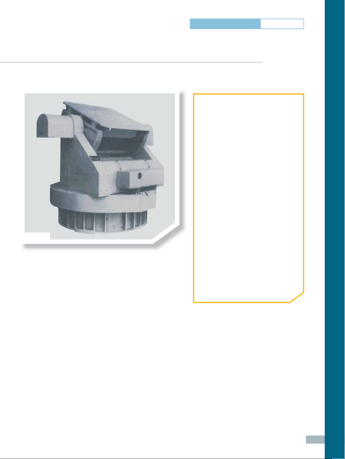
EL/AZ Positioners – Heavy Duty
AL-4216-1 • AL-4206-1 • AL-4207-1 • AL-4209-1 • AL-4210-1 • AL-4211-1
AL-4207-1
Our Legacy Series EL/AZ positioners provide accurate
rotation, velocity, and direction for customers involved
in antenna design and development.
➊ APPLICATIONS
• General Purpose Positioning
Subsystems
• Far-Field & Near-Field Antenna
Measurements
• Aircraft Measurements
• Indoor & Outdoor Use
➋ PRODUCT HIGHTLIGHTS
• Broad Selection – 6 Models
• Vertical Loads Ranging from 30,000
to 50,000 lbs (13,610 to 22,680 kg)
• Platform Sizes Ranging from
34.3 x 34.1 in to 92.5 in /
870 x 866 mm to 2350 mm (diameter)
• Excellent Angular Position Accuracy
• Low Backlash Design
• Precision Bearings
• Closed Loop Servo Control
• Industry-Standard Wiring
• Tachometers for Optimum Speed
Regulation & Control
• Wide Operating Temperature Range:
- 4° F to 140° F (- 20° C to + 60° C)
• Fully Enclosed Design of Drive Gear
Train & Data Take-Off
• Wide Variety of Available Options
> Rotary Positioners
Their rugged yet simple construction ensures maximum
reliability and trouble-free operation, yielding the best
size and weight versus performance ratio.
Typically, the primary components include the body, precise slew bearings, DC motors, gear reducers,
synchro assemblies, and limit switch assemblies. The turntable surface is designed with a threaded
mounting hole pattern for customer use. A Safe/Operate switch is included to ensure the safety
of working personnel.
65
Page 2

Specifi cations - Legacy Series EL/AZ Positioners Heavy Duty
Parameter Units
AL-4216-1 AL-4206-1 AL-4207-1 AL-4209-1 AL-4210-1 AL-4211-1
Positioner Model
Outline Dimension Drawing Number
Technical Notes
Operational
Bending Moment
Vertical Load
Azimuth
Delivered Torque
Elevation
Azimuth
Withstand Torque
Elevation
Drive Power
Nominal Speed
Standard Angle
Transducer Format
Standard
Accuracy
Maximum
Backlash
Elevation Limit-to-Limit Travel
Azimuth
Elevation
Azimuth
Elevation
Azimuth
Elevation
Azimuth
Elevation
10-2097 DCD10-2040 10-2098 10-2042 10-2043 10-2106
1, 2, 3 1, 2, 3 1, 2, 3 1, 2, 3 1, 2, 3 1, 2, 3
ft-lbs 30,000 35,000 45,000 150,000 300,000 300,000
kg-m 4,150 4,840 6,220 20,740 41,480 41,480
lbs 30,000 30,000 30,000 40,000 45,000 50,000
kg 13,610 13,610 13,610 18,140 20,410 22,680
ft-lbs 6,000 6,000 6,000 30,000 35,000 80,000
kg-m 830 830 830 4,150 4,840 11,060
ft-lbs 20,000 24,000 30,000 100,000 260,000 260,000
kg-m 2,765 3,320 4,150 13,830 35,950 35,950
ft-lbs 14,000 14,000 14,000 45,000 45,000 100,000
kg-m 1,940 1,940 1,940 6,220 6,220 13,830
ft-lbs 30,000 13,000 45,000 150,000 300,000 300,000
kg-m 4,150 1,800 6,220 20,740 41,480 41,480
hp 3/4 3/4 3/4 4 4 5
hp 3/4 3/4 3/4 4 4 5
rpm 0.3 0.3 0.3 0.2 0.15 0.1
deg/min 20 20 15 25 8 10
deg ± 0.03 ± 0.03 ± 0.03 ± 0.02 ± 0.02 ± 0.02
deg ± 0.04 ± 0.04 ± 0.04 ± 0.04 ± 0.03 ± 0.03
deg 0.05 0.05 0.04 0.03 0.02 0.02
deg 0.03 0.03 0.03 0.03 0.03 0.02
deg + 92, - 45 + 92, - 45 + 92, - 45 + 92, - 45 + 92, - 45 + 92, - 45
Dual Speed
Synchro
Dual Speed
Synchro
Dual Speed
Synchro
Dual Speed
Synchro
Dual Speed
Synchro
Dual Speed
Synchro
66
Physical
Height at 0° Elevation
Weight
Platform Size
Environmental
Operating Temperature
in 60 60 72 99 129 151
mm 1,420 1,420 1,829 2,510 3,277 3,835
lbs 4,200 6,300 6,700 20,500 45,000 48,000
kg 1,905 2,858 3,039 9,299 20,412 21,772
in 34.3 x 34.1 34.3 x 34.1 34.3 x 34.1
mm 871 x 866 871 x 866 871 x 866
- 4° F to 140° F (- 20° C to 60° C)
92.5
(diameter)
2350
(diameter)
47.2 x 47.2
1200 x 1200
92.5
(diameter)
2350
(diameter)
Page 3

Options*
Positioner Model
Parameter Units
AL-4216-1 AL-4206-1 AL-4207-1 AL-4209-1 AL-4210-1 AL-4211-1
Incremental Encoder
EN001
EN002
EN003
EN004
SR Slip Ring
RJ Rotary Joint
TH
EX Internal Harnessing
CF Connector Format
LS Leveling Screw (set)
ST Stow Lock
MM Mounting Thread
IC Interlock Circuit
*See Options Glossary on page 132 (-) N/A Opt Optional
(Standard Accuracy)
Accuracy – Azimuth
Accuracy – Elevation
Direct Incremental Encoder
(High Accuracy)
Accuracy – Azimuth
Accuracy – Elevation
Direct Absolute Encoder
(High Accuracy)
Accuracy – Azimuth
Accuracy – Elevation
Absolute Encoder
(Standard Accuracy)
Accuracy – Azimuth
Accuracy – Elevation
3
Central Thru-Hole Inner
Diameter
Opt Opt Opt Opt Opt Opt
deg ± 0.03 ± 0.03 ± 0.03 ± 0.02 ± 0.02 ± 0.02
deg ± 0.04 ± 0.04 ± 0.04 ± 0.04 ± 0.03 ± 0.03
Opt Opt Opt Opt Opt Opt
deg ± 0.005 ± 0.005 ± 0.005 ± 0.005 ± 0.005 ± 0.005
deg ± 0.005 ± 0.005 ± 0.005 ± 0.005 ± 0.005 ± 0.005
Opt Opt Opt Opt Opt Opt
deg ± 0.005 ± 0.005 ± 0.005 ± 0.005 ± 0.005 ± 0.005
deg ± 0.005 ± 0.005 ± 0.005 ± 0.005 ± 0.005 ± 0.005
Opt Opt Opt Opt Opt Opt
deg ± 0.03 ± 0.03 ± 0.03 ± 0.02 ± 0.02 ± 0.02
deg ± 0.04 ± 0.04 ± 0.04 ± 0.04 ± 0.03 ± 0.03
SR051L
SR101L
-----in -----mm ----- EX002 EX002 EX002 EX002 EX002 EX002
------
SR201L
SR301L
SR402L
SR502L
RJ12U
RJ18U
RJ26U
RJ40U
RJ50U
LS002-10 LS002-10 LS002-10 LS002-5 LS002-12 LS002-24
ST002L
ST002E
MM002
MM003
IC002 IC002 IC002 IC002 IC002 IC002
SR051L
SR101L
SR201L
SR301L
SR402L
SR502L
RJ12U
RJ18U
RJ26U
RJ40U
RJ50U
ST002L
ST002E
MM002
MM003
SR051L
SR101L
SR201L
SR301L
SR402L
SR502L
RJ12U
RJ18U
RJ26U
RJ40U
RJ50U
ST002L
ST002E
MM002
MM003
SR512L
SR812L
RJ12U
RJ18U
RJ26U
RJ40U
RJ50U
ST002L
ST002E
MM002
MM003
SR512L
SR812L
RJ12U
RJ18U
RJ26U
RJ40U
RJ50U
ST002L
ST002E
MM002
MM003
SR512L
SR812L
RJ12U
RJ18U
RJ26U
RJ40U
RJ50U
ST002L
ST002E
MM002
MM003
> Rotary Positioners
67
Page 4

supplied accessories
>
CD-ROM Documentation Set:
User Manual (Installation, Setup, Operation & Maintenance)
technical notes
1 All accuracy data is based on no-load conditions.
Contact ORBIT/FR for accuracy under load conditions.
2 All models are equipped with adjustable limit switches
capable of approx 20° to 900° total travel. When rotary
joint and slip ring options are specifi ed, limit switches
remain but are electrically disabled.
Multi-axis positioners are factory-set at:
• Elevation Axis: 137° (+ 92 to - 45°)
• Azimuth Axis: 400° (± 200°)
3 Slip Ring Option Notes:
• Certain slip ring options may require an extension
cap that protrudes above the turntable surface.
Positioner height may increase. Consult ORBIT/FR.
• Slip ring contacts for customer use are provided
with dedicated connectors.
ORDERING INFORMATION
• Refer to Legacy Series EL/AZ Positioners
– Heavy Duty Specifi cation Table
68
 Loading...