

Page 1
AL-4160 SERIES
>
Positioner Controller, Simultaneous
AL-4164 & AL-4166
AL-4164
AL-4166
AL-4164 and AL-4166 programmable positioner
controllers offer real-time control of positioning
subsystems used in near-fi eld and far-fi eld antenna
measurement systems.
Typically, they may be confi gured to drive planar
scanners and general purpose far-fi eld positioners
that are encoder-based or involve simultaneous
motion.
➊ APPLICATIONS
• Near-Field & Far-Field Antenna
Measurements
• Encoder-Based Positioners
& Scanners
• Light, Medium & Heavy Duty
Positioning Subsystems
➋ PRODUCT HIGHTLIGHTS
• Simultaneous Control Up to 4 Axes
• 4 Independent PWM Channels
• Factory-Confi gurable Armature
Output Voltage (24, 48 or 90 VDC)
• Built-In Power Control Unit (PCU)
• Absolute & Incremental Encoder
Support
• Brush & Brushless Motor Support
• 8 TTL I/O Lines for Auxiliary
Component Control
• User-Friendly Axis Confi guration
Software
• Dynamic Density Control (DDC)
• Communication to Host PC
Supported by LAN, RS-232 & CAN
Bus
> Positioner Controllers, PCUs & LCUs
Series Overview
Model AL-4162 AL-4164 AL-4166
Horsepower Up to 1/3 Up to 3/4 Up to 1.5
Number of Axes 2 4 4
15
Page 2

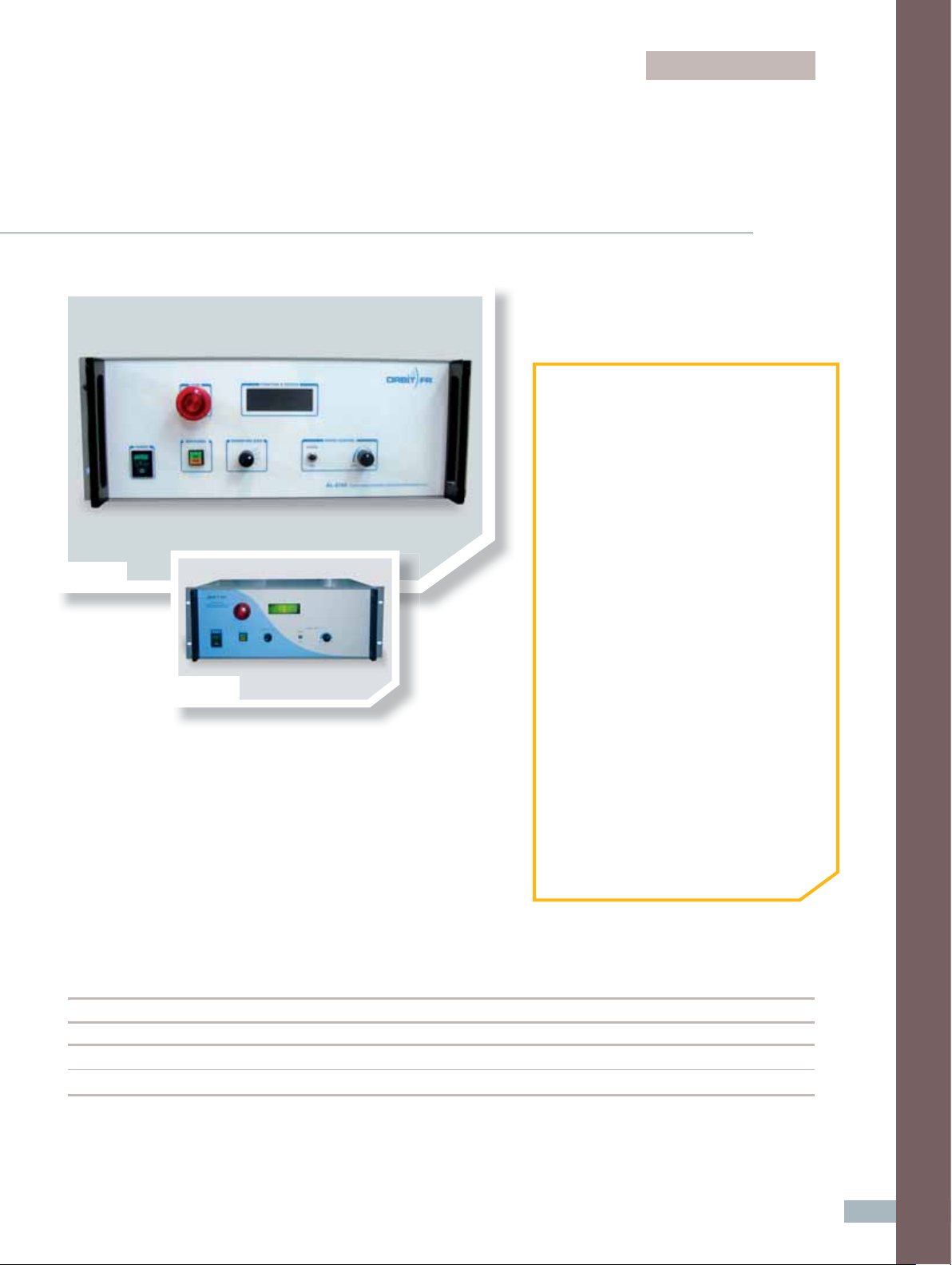
front panel
position correction
>
Controls:
n AC Power On/Off
n Axis Select
n Direction/Speed
- Coarse & Fine
n Remote/Local Control (BUS/PANEL)
n Emergency Stop (E-Stop)
>
Displays & Indicators:
n Axis Position
n Limit Indicators
n Homing Status
n Homing Completed
position sensors
>
Axis-Independent Position Sensor Selection:
n Incremental Encoder & Absolute Encoder (EnDat®)
velocity sensors
>
Axis-Independent Velocity Sensor Selection:
n Incremental Encoder & Tachometer
n On-the-Fly Calculation Using Linear Interpolation
n Up to 40,000 Points (Can Be Divided – 10,000 Points
Per Axis)
n Mapping in User Selectable Units
n Inverse/Transpose Table
n Set Table Data – Constant/Linear
n Load Table from File
onboard programming
n Run Up to 10 Programs in Parallel
supplied accessories
>
CD-ROM Documentation Set:
n User Manual (Installation, Setup, Operation)
n Programming Reference Manual
n Software Setup Utility
>
Cables:
n Cable, CAN, DB9 to RJ45
n Cable, RS-232, DB9 to RJ45
n AC Power Cord, IEC-320 (F) to Plug
options
closed loop motion control algorithms
n User Selectable PID or PIV Motion Control Filters
n Dynamic Braking
n Comprehensive Motion Profi les – Velocity, Parabolic
Ramping, S-Curve & Acceleration/Deceleration
n Single or Dual Feedback Encoders
n 3 Sets of Control Filter Scheduling
- In-Motion
- In-Settling
- In-Position
n BEMF Feedback Circuits
data recording
n Data Recording Buffer Up to 100,000 Points
n Simultaneous Recording Up to 10 Vectors
n Record Up to 100,000 Vectors
trigger functions
n Supports Discrete Position Trigger Tables
n User Selectable Pulse Polarity
n User Selectable Pulse Width
o Opt. 001 - PC-Based CAN-PCI Communication Card
o Opt. 002 - USB to CAN Adaptor
o Opt. 101 - Additional Manual Set
o Opt. 102 - International Localization
(Specify Country & Voltage)
o Optional n Standard
ORDERING INFORMATION
• AL-4164 Positioner Controller, 4 Axis, 3/4 HP
• AL-4166 Positioner Controller, 4 Axis, 1.5 HP
1. Start with Base Series: AL-4164 or AL-4166
2. Match Desired Voltage to Each Axis (1, 2, 3 & 4)
3. Select Voltage Assignment Using Table
Ref. Designator Voltage Assignment
A 105 VDC
B 48 VDC
C 24 VDC
Ordering Examples:
AL-4164-1A-2A-3B-4C or AL-4166-1A-2A-3B-4C
16
Page 3

Specifi cations - AL-4160 Series Simultaneous Controllers
Model AL-4162 AL-4164 AL-4166
Operational
• AC Power On/Off
• Axis Select
Front Panel Controls
& Indicators
• Coarse/Fine Speed
• Speed/Direction Control
• Local/Remote (Panel/Bus)
• Emergency Stop (Latching Panic Button)
• Digital Display w/ Limit Indicators
Correction Table Support
(Geometrical Error)
Electrical
AC Input Power
Power Dissipation
Controlled Axes
EMI Filtering
VDE Tests
Speed Control Range
(User-selectable)
Supported Position Sensors
Communication Links
Trigger Functions
Data Take-Off Accuracy
Optional (Opt. 009)
• 115/230 VAC +/- 10%, 47-63 Hz, single phase
• 10A rms @ 115 VAC
• 5A rms @ 230 VAC
0.7 KVA max 1.3 KVA max
2 Simultaneous control 4 Simultaneous control
MIL-STD-461/2, VDE 0871/3.68
• Leakage: 1,500 VAC
• Insulation: 500 VDC
• Bonding: 25 ADC
• Coarse: 0-100%
• Fine: 0-18%
Incremental Encoder
• RS-232 (115,200 Baud Rate)
• CAN Bus
Trigger Out/In
Up to 29 bit resolution
• Selectable for each axis via setup utility
• Incremental Encoder
®
Absolute Encoder
• EnDat
• RS-232 (115,200 Baud Rate)
• CAN Bus
• LAN
> Positioner Controllers, PCUs & LCUs
Supported Motion Control
Filters
Control Filter Scheduling
Linked Axes
Load Inductance
Maximum Motor Size
Motor Armature Supply
(By Current)
User Selectable PID/PIV
In-Motion & In-Settling In-Motion, In-Settling, In-Position
Axes 1 & 2 Only
No output choke required
1/3 HP 3/4 HP 1.5 HP
• Axis 1: 4 Amps (avg.)
• Axis 2: 4 Amps (avg.)
• Axis 1: 8 Amps (avg.)
• Axis 2: 8 Amps (avg.)
• Axis 3: 8 Amps (avg.)
• Axis 4: 8 Amps (avg.)
• Axis 1: 15 Amps (avg.)
• Axis 2: 15 Amps (avg.)
• Axis 3: 6 Amps (avg.)
• Axis 4: 6 Amps (avg.)
17
Page 4

Model AL-4162 AL-4164 AL-4166
Electrical
Factory-Confi gurable Armature Output Voltage
Motor Armature Supply
(By Voltage)
Motor Armature Current
Limiting
Motor Field Supply
0 to ± 90 VDC
• 1 to 5 amps
• Each Axis Selectable Via Internal
Dip Switch
110 VDC, 2 Amps Max Continuous
• 0 to ± 90 VDC
• 0 to ± 48 VDC
• 0 to ± 24 VDC
• 1 to 15 amps
• Each Axis Selectable Via Internal Dip Switch or Setup Utility
Motor Driver Method
Motor Direction
Dynamic Braking Supply
Compatible Local Control Units
(LCU)
Physical
Dimensions
Weight
Environmental
Operating Temperature
Storage Temperature
Relative Humidity
• Filtered Pulse Width Modulated (PWM)
• 32 kHz Nominal Switching Rate (above audible range)
Bi-directional
24 VDC, 2 Amps Max
-
• 19.0 in (48.3 cm) Width
• 3.5 in (8.9 cm) Height
• 15.0 in (38.0cm) Depth
33 lbs (15 kg) 70.4 lbs (31.9 kg)
32° to 122° F (0° to 50° C)
- 4° to 167° F (- 20° to 75° C)
90%
• AL-4146-2L Series
• AL-4188 Series
• 19.0 in (48.3 cm) Wide
• 7.0 in (17.8 cm) High
• 19.5 in (49.4 cm) Deep
18
 Loading...