

Page 1
Orbit X303
Assembly Instrucons
Page 2

Table of Contents
Owner’s Manual Orbit X303
Spare parts list ....................................................................................................................... 3
F
asteners drawing ................................................................................................................
4
A
ssembly step(1) ........................................................................................................... 5-
6
A
ssembly step(2) ........................................................................................................... 7-
8
A
ssembly step(3) ......................................................................................................... 9-1
0
A
ssembly step(4) ....................................................................................................... 11-1
2
A
ssembly step(5) ....................................................................................................... 13-1
4
A
ssembly step(6) ....................................................................................................... 15-1
6
A
ssembly step(7) ....................................................................................................... 17-1
8
W
arranty card ................................................................................................................. 19-2
1
C
AUTION:
E
xercise of a strenuous nature, as is customarily done on this equipment, should not be undertaken
w
ithout first consulng a physician. No specific health claims are made or implied as they relate to
t
he equipment. Measurements made by the equipment are believed to be accurate, but only the
m
easurements of your physician should be relied upon.
I
MPORTANT:
R
ead all instrucons carefully before using this product. Retain this product owner's manual for
future reference.
Page 3

Spare parts list
3
No. Descripon Note Qty.
1 le base frame 1
2 right base frame 1
3 ground link support plate 2
4 hexagon bolt M10*90 8
5 washer Φ10 16
6 lock nut M10 8
7 le upright frame 1
8 right upright frame 1
9 barbell bar lock nut Φ25*M12*35 24
10 barbell bar hang rod Φ25*M12*98 24
11 hexagon bolt M12*35 14
12 spring washer Φ12 16
13 washer Φ12 30
14 lock nut M12 6
15 hexagon bolt M12*75 6
16 headless hexagon socket bolt M8*10 4
17 hexagon bolt M12*25 2
18 up link plate 2
19 guide rod 2
20 barbell bar plug 2
21 barbell bar sleeve 2
22 barbell bar 1
23 le sliding sleeve 1
24 right sliding sleeve 1
25 rubber cushion Φ60*Φ55*Φ27*28 4
26 le safety hook 1
27 right safety hook 1
28 hexagon bolt M12*80 2
29 upper frame 1
30 le weight plate holder 1
31 right weight plate holder 1
32 core trainer 1
33 stop collar Φ25*Φ20*6 1
34 limit sha Φ22*M12*39.5 1
35 long safety catch 2
36 short safety catch 2
37 le horizontal bar 1
38 right horizontal bar 1
39 barbell clamp collar Φ50 2
40 spring collar Φ50 4
Page 4
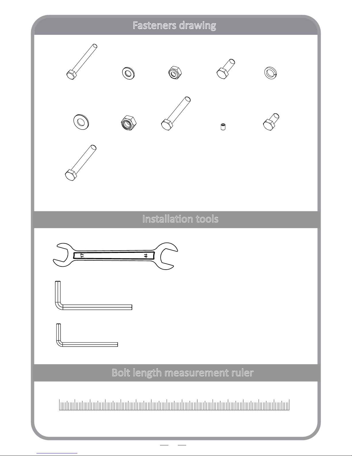
Fasteners drawing
4
Bolt length measurement ruler
Installaon tools
4 5 6 11 12
13
28
14
15 16 17
0 1 6 7 8 9 10 11 12 13 14 152 3 4 5 cm
17-19 SPANNER 2PCS
6MM INNER HEXAGON SPANNER 1PC
4MM INNER HEXAGON SPANNER 1PC
Page 5
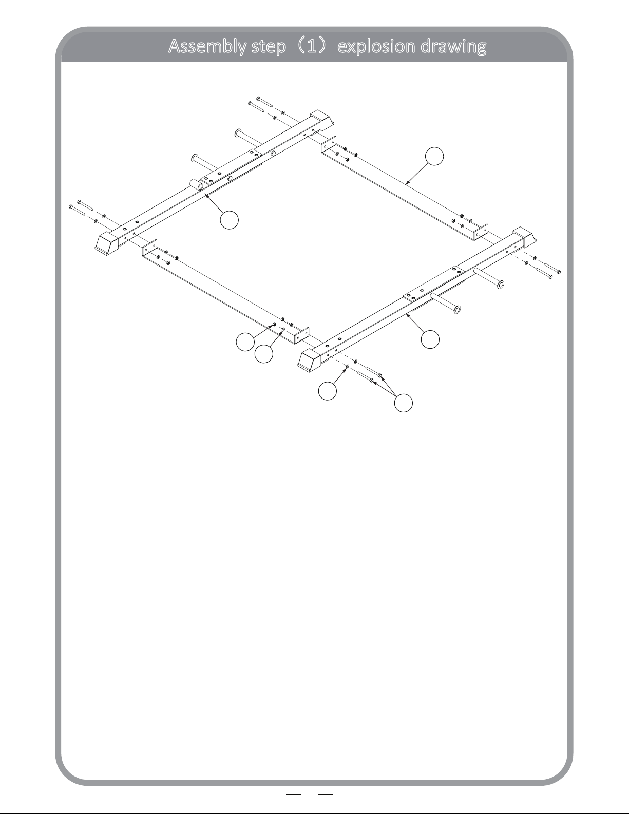
Assembly step(1)explosion drawing
5
5
5
4
1
2
3
6
No. Descripon Note Qty.
1 le base frame 1
2 right base frame 1
3 ground link support plate 2
4 hexagon bolt M10*90 8
5 washer Φ10 16
6 lock nut M10 8
Page 6

Assembly step(1)drawing
6
Assembly step(1)assembly instrucon
1. Fix ground link support plate (3) fastening on le base frame (1) with right base frame (2)
using: M10*90 hexagon bolt (4), Ф10 washer (5), M10 lock nut (6)
CAUTION: All bolts should be semi-ghtened to allow fine tune.
Page 7
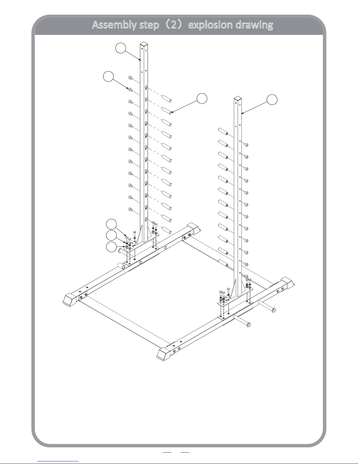
Assembly step(2)explosion drawing
7
7
10
11
12
13
8
9
No. Descripon Note Qty.
7 le upright frame 1
8 right upright frame 1
9 barbell bar lock nut Φ25*M12*35 24
10 barbell bar hang rod Φ25*M12*98 24
11 hexagon bolt M12*35 10
12 spring washer Φ12 10
13 washer Φ12 10
Page 8

Assembly step(2)drawing
8
Assembly step(2)assembly instrucon
1. Fix le upright frame (7) fastening on le base frame using: M12*35 hexagon bolt (11),
Ф12 spring washer (13), Ф12 washer (7)
2
. Fix right upright frame (8) fastening on right base frame using: M12*35 hexagon bolt (11),
Ф12 spring washer (13), Ф12 washer (7)
3
. Fix barbell bar lock nut(9) and barbell bar hang rod(10) fastening on le upright frame(7)
and right upright frame(8)
CAUTION: All bolts should be semi-ghtened to allow fine tune.
Page 9

Assembly step(3)explosion drawing
9
131314
15
16
16
13
16
16
18
17
20
21
22
23
24
25
26
27
19
No. Descripon Note Qty.
13 washer Φ12 10
14 lock nut M12 4
15 hexagon bolt M12*75 4
16 headless hexagon socket bolt M8*10 4
17 hexagon bolt M12*25 2
18 up link plate 2
19 guide rod Φ25*2020 2
20 barbell bar plug 2
21 barbell bar sleeve 2
22 barbell bar 1
23 le sliding sleeve 1
24 right sliding sleeve 1
25 rubber cushion Φ60*Φ55*Φ27*28 4
26 le safety hook 1
27 right safety hook 1
Page 10

Assembly step(3)drawing
10
Assembly step(3)assembly instrucon
1
. Fit guide rod (19) on le base frame (1) & right base frame (2) using:
M8*10 headless hexagon socket bolt (16)
2
. Put right sliding sleeve (24) and le sliding sleeve (23) on barbell bar (22)
3
. From top of right hand guide rod, in turn insert rubber cushion(25),
le safety hook(26),rubber cushion(25), from top of le hand guide rod in turn insert rubber
cushion(25),right safety hook(27),rubber cushion(25)
With help from a second person and hold the barbell horizontally,
carefully slide the sliding sleeves into guide bars.
Be careful not to use excessive force to cause damage to bearing inside sleeves.
If jammed, try to pull out and redo or seek assistance from dealer.
4
. Plug guide rod (19) into up link plate (18), then connect up link plate (18) to
le upright frame (7) & right upright frame (8) using:
M12*75 hexagon bolt (15), Ф12 washer (13), M12 lock nut (14)
5
. Tighten guide rod (19) to up link plate (18) using:
M8*10 headless hexagon socket bolt (16)
6
. Fit barbell bar plug (20) and barbell bar sleeve (21) fastening on barbell bar (22) using:
M12*25 hexagon bolt (17), Ф12 washer (13)
Page 11

Assembly step(4)explosion drawing
11
15
28
13
13
12
29
13
14
15
28
No. Descripon Note Qty.
12 spring washer Φ12 2
13 washer Φ12 6
14 lock nut M12 2
15 hexagon bolt M12*75 2
28 hexagon bolt M12*80 2
29 upper frame 1
Page 12

12
Assembly step(4)drawing
Assembly step(4)assembly instrucon
1. Fix upper frame (29) fastening on le upright frame & right upright frame using:
M12*75 hexagon bolt (15), M12*80 hexagon bolt (28), Ф12 spring washer (12),
Ф12 washer (13), and M12 lock nut (14)
CAUTION: All bolts should be semi-ghtened to allow fine tune.
Page 13

Assembly step(5)explosion drawing
13
11
31
12
13
33
34
30
32
No. Descripon Note Qty.
11 hexagon bolt M12*35 4
12 spring washer Φ12 4
13 washer Φ12 4
30 le weight plate holder 1
31 right weight plate holder 1
32 core trainer 1
33 stop collar Φ25*Φ20*6 1
34 limit sha Φ22*M12*39.5 1
Page 14

14
Assembly step(5)drawing
Assembly step(5)assembly instrucon
1. Fix le weight plate holder (30) fastening on le base frame using:
M12*35 hexagon bolt (11), Ф12 spring washer (12), Ф12 washer (13)
2. Fix right weight plate holder (31) fastening on right base frame using:
M12*35 hexagon bolt (11), Ф12 spring washer (12), Ф12 washer (13)
3. Fix core trainer(32) on right base frame using: limit sha(34),stop collar(33)
CAUTION: All bolts should be semi-ghtened to allow fine tune.
Page 15

Assembly step(6)explosion drawing
15
35
36
38
37
36
35
No. Descripon Note Qty.
35 long safety catch 2
36 short safety catch 2
37 le horizontal bar 1
38 right horizontal bar 1
Page 16

16
Assembly step(6)drawing
Assembly step(6)assembly instrucon
1. Put le horizontal bar (37), long safety catch (35), short safety catch (36)
on le upright frame
2
. Put right horizontal bar (38), long safety catch (35), short safety catch (36)
on right upright frame
Page 17

Assembly step(7)explosion drawing
17
39
39
No. Descripon Note Qty.
39 barbell clamp collar Φ50 2
40 spring collar Φ50 4
Page 18

18
Assembly step(7)drawing
Assembly step(7)assembly instrucon
1. Fix barbell clamp collar(39) on barbell bar
2
. Fix spring collar(40) respecvely on le weight plate holder and right weight plate holder
You’ve now completed assembly of Orbit X303 Smart Way Smith machine.
P
lease test it makes sure it runs smoothly before fastening ALL nuts and bolts.
I
f you come across any difficulty during assembly, contact dealer for help.
Page 19

19
D
omesc Warranty Terms and Condions
O
rbit warrants X303 Smart Way Smith free from defects in material and workmanship unde
r
n
ormal use at home. Any use in commercial, instuonal or rental will void this warranty. Warrant
y
p
eriod begins from date of purchase. Only the person on original purchase invoice and/or warranty
c
ard is covered. It is non-transferrable.
O
ur goods come with consumer guarantees that cannot be excluded under the Australia
n
C
onsumer Law. You are entled to a replacement or refund for a major failure and can ask fo
r
c
ompensaon for any drop in value of goods or service. You are also entled to have the goods
r
epaired or replaced if the failure does not amount to a major failure. Please discuss with Orbi
t
S
ervice department or refer to ACL for details of consumer guarantees.
W
arranty Registraon and Claim Procedures
W
arranty commitments are valid only with a completed warranty card that is returned within 1
5
d
ays from date of purchase or registered online with Orbit Fitness that includes the product seria
l
n
umber (where applicable) and details of purchase as in aached sheet. Proof of purchase in th
e
f
orm of tax invoice from an Orbit store, Orbit Online, Orbit authorised dealer or distributor will b
e
r
equired when raising a warranty claim.
T
o lodge a warranty claim, have your purchase details handy and contact Orbit Service departmen
t
d
uring business hours at Unit 308, 396 Scarborough Beach Road, Osborne Park, WA 6017 in perso
n
o
r via post, by telephone 0061-8-62413050 or by e-mail service@orbiitness.com.au within th
e
w
arranty period. Customer may be requested to return defecve or damaged product to Orbit
s
ervice department or to the Orbit store that the product was purchased from. Whereas a produc
t
i
s too big or heavy for customer to handle, an on-site service call can usually be organized. However
,
t
his may incur a call-out fee when the claim is lodged outside the labour cost warranty period. Orbi
t
r
eserves the right to charge customer labour, parts and call-out fee if it establishes that a warrant
y
c
laim is not valid. Please refer to “items not covered”.
W
hat is covered
M
etal structure frame: 2 years limited warranty (excl rust and paint)
M
echanical parts: 1 year limited warranty (incl bearing, bushing)
W
ear and tear parts: 6 months on pulley and steel cable
90 days on foam, upholstery (including stching)
L
abour cost 1 year limited warranty
Page 20

20
I
tems Not Covered
T
his warranty does not apply to any failure of the product, or any parts of the product, due t
o
a
lteraons, modificaons, misuse, abuse, negligence, accident, incorrect assembly or imprope
r
m
aintenance. Faults as result of installaon by Orbit staff must be reported within 7 days, as do
c
oncerns, quesons aroused during or aer installaon by customer. Failure to follow warning i
n
t
he owners manual, or warning sckers placed on equipment may result in injury to person an
d
e
quipment and substanally void your warranty. Normal wear and tear due to use, transport
,
e
xposure to air and radiaon, material fague is not covered.
M
aintenance ps
M
otorised products, including treadmills, some exercise bikes and cross trainers may require
s
cheduled service for safety guarantee and smooth operaon of your product. Please refer to
‘
service card’ enclosed in your user manual. For products that do not come with a service card,
p
lease refer to below general advice or contact Orbit service department for more specific advices.
A
ll Orbit products are designed and produced for indoor usage-do not place them outdoor or
e
xpose them to weather.
A
lways inspect parts of safety concern prior to exercise, eg. Steel cable, handle bar, foot pedal,
c
hains and bands etc. Repair or replace any damaged or worn parts as early as possible so to avoid
i
njury.
A
s part of Orbit’s normal installaon and set-up process, all bolts must be ghtened and checked
a
er the first 1 to 2 hours of initial usage and then periodically. Loose bolts and nuts may come off,
c
ausing damage, which may void warranty and can cause potenal danger to the user as well.
A
er training, always wipe down your Orbit machine. Perspiraon that connuously seles on the
f
rame and pads may cause rust or damage to the unit. Damage resulng from lack of proper
m
aintenance will not be covered under warranty. To clean upholstery and frame, use a mild soap
a
nd warm water. Dry with a clean towel.
I
f any cracks appear in the frame, stop using your product immediately and contact Orbit Service
d
epartment.
Page 21

21
I
mportant Important Important ! Important !
W
ARRANTY CARD MUST BE COMPLETED AND RETURNED TO ORBIT OR REGISTERED ONLINE WITHI
N
1
5 DAYS OF PURCHASE. Failure to comply may void manufacturer’s warranty.
N
ame
A
ddress
E
mail
P
hone
A
ge group below 25 25-35 35-45 45-55 55 plus
S
ex Male Female
P
roduct code on invoice
D
ate of purchase & invoice number
M
ailing address
S
ervice Department
O
rbit Health & Fitness Soluons
U
nit 308, 396 Scarborough Beach Road
O
sborne Park, Western Australia 6017
w
ww.orbiitness.com.au
 Loading...