

Page 1
p 801 295 9820
f 801 951 5815
www.fluid-studio.net
1065 South 500 West
Bountiful, Utah 84010
proof no: 1
date:
07.20.10
des: SM spck: XX
job no: NA
client: Orbit
sku: 55660
upc: NA
file name: 55660-24 rA.indd
software: InDesign CS5
colors
additional instructions:
· Translations Approval Code: ·
color
non printing
PMS
????
PMS
????
color
non printing
PMS
????
Registration
K
Printers are responsible for
meeting print production
requirements. Any changes
must be approved by the
client and Fluid Studio.
printed piece must meet
designated specifications
on this form.
dimensions:
flat: w: 11.25" h: 5.5"
finished (folded): w 3.75" d: 0" h 5.5"
© 2007 Fluid Studio. This
work is the property of Fluid
Studio, and cannot be used,
reproduced or distributed
in any way without their
express permission.
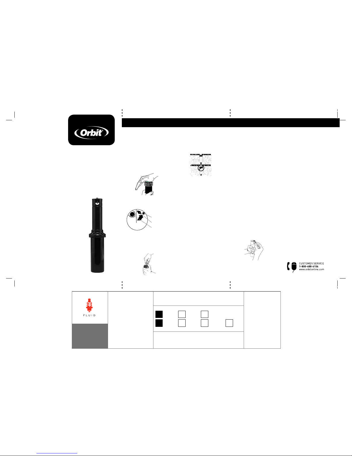
Voyager II® Professional
GEAR DRIVE
SPRINKLER
Regador profesional Voyager II®
accionado por engranajes
PN 55660-24 Rev A
ENGLISH
READ ALL INSTRUCTIONS PRIOR
TO INSTALLATION
Set the pattern before installation
The Voyager II
®
can be set to
rotate between 40° and 360°
(preset at 180°)
1. Turn the top of the head all
the way to the left until it stops
and then all the way to the
right. The top of the head must
be in this position to make
adjustments. (Figure 1).
2. Insert the plastic end of the key
into the pattern adjustment hole
(Figure 2).
3. Turn clockwise to increase
rotation; counterclockwise
to decrease rotation. Each
full turn increases/decreases
rotation by 90˚ (Figure 3).
Head installation
1. Flush sprinkler lines.
2. Thread the sprinkler onto a
riser and set the head flush
with the finished turf height
(Figure 4).
Note: DO NOT use pipe dope on
the threads. If necessary, use
thread seal tape.
Set the spray distance
after installation
Set with water on under system’s
normal operating pressure.
Note: Preinstalled nozzle (#
7) adjusts from 25 ft. to 45 ft.
depending on system water
pressure.
1. Insert the hex (metal) end
of the key into the distance
adjustment slot (Figure 2).
2. Turn clockwise to decrease
distance; counterclockwise to
increase distance.
Caution: DO NOT turn the
adjustment screw too far in
either direction—screw may
come free of threads.
Replace the nozzle
See Nozzle Specs for other
distance ranges and replace the
nozzle if needed.
1. To access the nozzle, insert the
plastic end of the key into the
lifter socket (Figure 2).
2. Turn the key 90° and pull
upward.
Note: the spring inside the
canister is very strong.
3. Firmly grip the sprinkler stem.
4. Insert the hex (metal) end
of the key into the distance
adjustment slot (Figure 2).
5. Turn the screw
counterclockwise until it is just
clear of the nozzle.
6. Apply water pressure to your
system and the nozzle will popout of the head. Or use pliers to
grip the edge of the nozzle and
pull it out.
7. Insert the replacement nozzle
so that the diffuser screw
channel is on top and turn the
diffuser screw back into place
(Figure 5).
8. Adjust distance if necessary
(see Set the Spray Distance).
Clean the filter
1. Remove grass and dirt around
the sprinkler head so you can
see the top 1 ½ in.
2. Unscrew the cap and remove
the stem assembly.
3. Use pliers to extract the filter
from the bottom of the stem
assembly.
4. Clean out debris and replace
filter.
5. Replace the stem assembly to
the sprinkler body and screw
tightly.
Pattern
Adjustment
Distance
Adjustment
O
rb
i
t
®
Professional
Pattern
Adjustment
Distance
Adjustm
ent
Orbit
®
Professional
.
.
.
.
.
.
.
.
.
.
.
.
.
.
.
.
.
.
.
.
.
.
.
.
.
.
.
.
.
.
.
.
.
.
.
.
.
.
.
.
.
.
.
.
.
.
.
.
.
.
.
.
.
.
.
.
.
.
.
.
.
.
.
.
.
.
.
.
.
.
.
.
.
.
.
.
.
.
.
.
.
.
.
.
.
.
.
.
.
.
.
.
.
.
.
.
.
.
.
.
.
.
.
.
.
.
.
.
.
.
.
.
.
.
.
.
.
.
.
.
.
.
.
.
.
.
.
.
.
.
.
.
.
.
.
.
.
.
.
.
.
.
.
.
.
.
.
.
.
.
.
.
.
.
.
.
.
.
.
.
.
.
.
.
.
.
.
.
.
.
.
.
.
.
.
.
.
.
.
.
.
.
.
.
.
.
.
.
.
.
.
.
.
.
.
.
.
.
.
.
.
.
.
.
.
.
.
.
.
.
.
.
.
.
.
.
.
.
.
.
.
.
.
.
.
.
.
.
.
.
.
.
.
.
.
.
.
.
.
.
.
.
.
.
.
.
.
.
.
.
.
.
.
.
.
.
.
.
.
.
.
.
.
.
.
.
.
.
.
.
.
.
.
.
.
.
.
.
.
.
.
.
.
.
.
.
.
.
.
.
.
.
.
.
.
.
.
.
.
.
.
.
.
.
.
.
.
.
.
.
.
.
.
.
.
.
.
.
.
.
.
.
.
.
.
.
.
.
.
.
.
.
.
.
.
.
.
.
.
.
.
.
.
.
.
.
.
.
.
.
.
.
.
.
.
.
.
.
.
.
.
.
.
.
.
.
.
.
.
.
.
.
. .
.
.
.
.
.
.
.
.
.
.
.
.
.
.
.
.
.
.
.
.
.
.
.
.
.
.
.
.
.
.
.
.
.
.
.
.
.
.
.
.
.
.
.
.
.
.
.
.
.
.
.
.
.
.
.
.
.
.
.
.
.
.
.
.
.
.
.
.
.
.
.
.
.
.
.
.
.
.
.
.
.
.
.
.
.
.
.
.
.
.
.
.
.
.
.
.
.
.
.
.
.
.
.
.
.
.
.
.
.
.
.
.
.
.
.
.
.
.
.
.
.
.
.
.
.
.
.
.
.
.
.
.
.
.
.
.
.
.
.
.
.
.
.
.
.
.
.
.
.
.
.
.
.
.
.
.
.
.
.
.
.
.
.
.
.
.
.
.
.
.
.
.
.
.
.
.
.
.
.
.
.
.
.
.
.
.
.
.
.
.
.
.
.
.
.
.
.
.
.
.
.
.
.
.
.
.
.
.
.
.
.
.
.
.
.
.
.
.
.
.
.
.
.
.
.
.
.
.
.
.
.
.
.
.
.
.
.
.
.
.
.
.
.
.
.
.
.
.
.
.
.
.
.
.
.
.
.
.
.
.
.
.
.
.
.
.
.
.
.
.
.
.
.
.
.
.
.
.
.
.
.
.
.
.
.
.
.
.
.
.
.
.
.
.
.
.
.
.
.
.
.
.
.
.
.
.
.
.
.
.
.
.
.
.
.
.
.
.
.
.
.
.
.
.
.
.
.
.
.
.
.
.
.
.
.
.
.
.
.
.
.
.
.
.
.
.
.
.
.
.
.
.
.
.
.
.
.
.
.
.
.
.
.
.
.
.
.
.
.
.
.
.
.
.
.
.
.
.
.
.
.
.
.
.
.
.
.
.
.
.
.
.
.
.
.
.
.
.
.
.
.
.
.
.
.
.
.
.
.
.
.
.
.
.
.
.
.
.
.
.
.
.
.
.
.
.
.
.
.
.
.
.
.
.
.
.
.
.
.
.
.
.
.
.
.
.
.
.
.
.
.
.
.
.
.
.
.
.
.
.
.
.
.
.
.
.
.
.
.
.
.
.
.
.
.
.
.
.
.
.
.
.
.
.
.
.
.
.
.
.
.
.
.
.
.
.
.
.
.
.
.
.
.
.
.
.
.
.
.
.
.
.
.
.
.
.
.
.
.
.
.
.
.
.
.
.
.
.
.
.
.
.
.
.
.
.
.
.
.
.
.
.
.
.
.
. .
.
.
.
.
.
.
.
.
.
.
.
.
.
.
.
.
.
.
.
.
.
.
.
.
.
.
.
.
.
.
.
.
.
.
.
.
.
.
.
.
.
.
.
.
.
.
.
.
.
.
.
.
.
.
.
.
.
.
.
.
.
.
.
.
.
.
.
.
.
.
.
.
.
.
.
.
.
.
.
.
.
.
.
.
.
.
.
.
.
.
.
.
.
.
.
.
.
.
.
.
.
.
.
.
.
.
.
.
.
.
.
.
.
.
.
.
.
.
.
.
.
.
.
.
.
.
.
.
.
.
.
.
.
.
.
.
.
.
.
.
.
.
.
.
.
.
.
.
.
.
.
.
.
.
.
.
.
.
.
.
.
.
.
.
.
.
.
.
.
.
.
.
.
.
.
.
.
.
.
.
.
.
.
.
.
.
.
.
.
.
.
.
.
.
.
.
.
.
.
.
.
.
.
.
.
Pattern
Adjustment
Distance
Adjustment
Orbit
®
Professional
Figure 1
Figure 3
Figure 4
Figure 5
Pattern
Adjustment
Distance
Adjustment
Orbit
®
Professional
Figure 2
Distance
Adjustment
Lifter Socket
Pattern
Adjustment
CAUTION
• Foroutdoorusewith
cold water only.
• Donotspraynear
electrical connections.
PRECAUCIÓN
• Parausoenexteriores
con agua fría solamente.
• Norocíecercade
conexiones eléctricas.
Page 2
n Denotes square spacing.
s Denotes equilateral
triangular spacing.
Data represent test results
in zero wind. Adjust for local
conditions.
ESPAÑOL
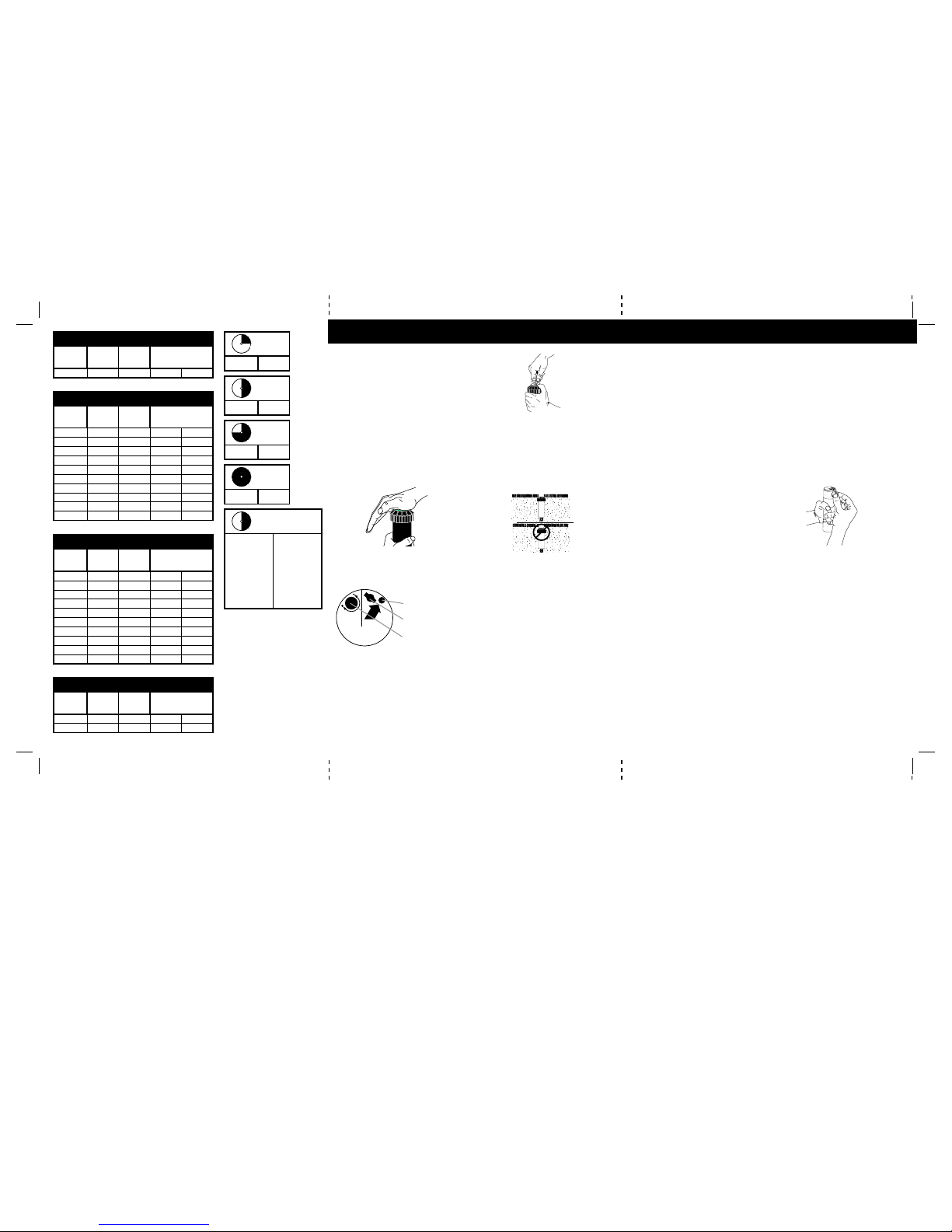
3.0 Preinstalled Nozzle
Spacing
(ft.)
Pressure
PSI
Flow
GPM
Precip in/hr.
40 40 3.0 0.36 0.42
1.0, 2.0, 3.0, 4.0 Eco-Pattern Nozzles (26-35 ft)
Spacing
(ft.)
Pressure
PSI
Flow
GPM
Precip in/hr.
26 40 1.0-4.0 0.57 0.66
27 40 1.0-4.0 0.53 0.61
28 40 1.0-4.0 0.49 0.57
29 40 1.0-4.0 0.46 0.53
30 40 1.0-4.0 0.43 0.49
31 40 1.0-4.0 0.40 0.46
32 40 1.0-4.0 0.38 0.43
33 40 1.0-4.0 0.35 0.41
34 40 1.0-4.0 0.33 0.38
35 40 1.0-4.0 0.31 0.36
L0.5, L1.0, L1.5, L2.0 Eco-Pattern Nozzles (16-25 ft)
Spacing
(ft.)
Pressure
PSI
Flow
GPM
Precip in/hr.
16 40 0.5-2.0 0.75 0.87
17 40 0.5-2.0 0.67 0.77
18 40 0.5-2.0 0.59 0.69
19 40 0.5-2.0 0.53 0.62
20 40 0.5-2.0 0.48 0.56
21 40 0.5-2.0 0.44 0.50
22 40 0.5-2.0 0.40 0.46
23 40 0.5-2.0 0.36 0.42
24 40 0.5-2.0 0.33 0.39
25 40 0.5-2.0 0.31 0.36
8.0, L3.0 Specialty Nozzles
Spacing
(ft.)
Pressure
PSI
Flow
GPM
Precip in/hr.
32 40 3.0 0.56 0.65
52 40 8.0 0.57 0.66
n s
n s
n s
n s
LEA TODAS LAS INSTRUCCIONES
ANTES DE LA INSTALACIÓN
Ajuste de la modalidad
Antes de la instalación
Voyager II se puede ajustar
para que gire entre 40° y 360°
(preajustado en 180°)
1. Gire completamente la parte
superior del cabezal hacia la
izquierda hasta que tope; luego,
gírela completamente hacia la
derecha. Éste es el punto de
partida para la rotación (figura 1).
2. Inserte el extremo plástico de
la llave en el orificio de ajuste
de modalidad (figura 2).
3. Gire en dirección de las
manecillas del reloj para
aumentar la rotación y en
dirección contraria para
disminuirla. Cada giro completo
disminuye o aumenta la
rotación en 90˚ (figura 3).
Instalación del cabezal
1. Haga correr agua por las
tuberías del regador.
2. Inserte el regador en el
elevador y ajuste el cabezal a
ras con la altura acabada del
césped (figura 4).
Nota: NO use aditivos para
tubos en las roscas. Si es
necesario, use solamente cinta
aislante.
3. Destornille la tapa y retire
el vástago del regador del
recipiente. Tenga cuidado con
los desechos que puedan caer
al recipiente.
4. Coloque el vástago del regador
con la flecha apuntando hacia el
borde derecho de la rotación.
5. Vuelva a colocar el vástago
del regador deslizándolo en el
recipiente y apriete la tapa.
Ajuste de la distancia del rocío
Después de la instalación
Ajuste con el agua corriendo en la
presión de funcionamiento normal
del sistema.
Nota: la boquilla preinstalada (#
7) se ajusta de 7,6 m a 3,7 m (25
pies a 45 pies) dependiendo de la
presión del sistema.
1. Inserte el extremo hexagonal
(metal) de la llave en la ranura
de ajuste de distancia (figura 2).
2. Gire en dirección de las
manecillas del reloj para
disminuir la distancia y en
dirección contraria para
aumentarla.
Precaución: NO gire demasiado
el tornillo de ajuste, ya que se
puede salir de las roscas.
Reemplazo de la boquilla
Consulte las especificaciones de
la boquilla para conocer otros
rangos de distancia; si es
necesario, reemplácela.
1. Para acceder a la boquilla,
inserte el extremo plástico
de la llave en el manguito del
elevador (figura 2).
2. Gire la llave en 90º y tire de ella
hacia arriba.
3. Tome firmemente el vástago
del regador. Nota: el resorte del
interior del recipiente es muy
resistente.
4. Inserte el extremo hexagonal
(metal) de la llave en la ranura
de ajuste de distancia (figura 2).
5. Gire el tornillo en dirección
contraria a la de las manecillas
del reloj hasta que esté apenas
alejado de la boquilla.
Precaución: NO gire demasiado
el tornillo de ajuste, ya que se
puede salir de las roscas.
6. Use alicates para agarrar las
asas de la boquilla y sáquela.
7. Inserte la boquilla de repuesto
con las asas hacia arriba y
vuelva a atornillar el tornillo
(figura 5).
8. Ajuste la distancia si es
necesario (consulte la sección
Ajuste de la distancia del rocío).
Limpieza del filtro
1. Retire el pasto y la tierra que
rodea al cabezal del regador
hasta ver 3,8 cm de la parte
superior.
2. Destornille la cubierta y retire
el conjunto del vástago.
3. Extraiga el filtro con alicates
desde el fondo del conjunto del
vástago.
4. Limpie los desechos y cambie
el filtro.
5. Vuelva a colocar el conjunto
del vástago en el cuerpo del
regador y atornille bien.
Pattern
Adjustment
Distance
Adjustment
O
rb
i
t
®
Professional
Pattern
Adjustment
Distance
Adjustm
ent
Orbit
®
Professional
.
.
.
.
.
.
.
.
.
.
.
.
.
.
.
.
.
.
.
.
.
.
.
.
.
.
.
.
.
.
.
.
.
.
.
.
.
.
.
.
.
.
.
.
.
.
.
.
.
.
.
.
.
.
.
.
.
.
.
.
.
.
.
.
.
.
.
.
.
.
.
.
.
.
.
.
.
.
.
.
.
.
.
.
.
.
.
.
.
.
.
.
.
.
.
.
.
.
.
.
.
.
.
.
.
.
.
.
.
.
.
.
.
.
.
.
.
.
.
.
.
.
.
.
.
.
.
.
.
.
.
.
.
.
.
.
.
.
.
.
.
.
.
.
.
.
.
.
.
.
.
.
.
.
.
.
.
.
.
.
.
.
.
.
.
.
.
.
.
.
.
.
.
.
.
.
.
.
.
.
.
.
.
.
.
.
.
.
.
.
.
.
.
.
.
.
.
.
.
.
.
.
.
.
.
.
.
.
.
.
.
.
.
.
.
.
.
.
.
.
.
.
.
.
.
.
.
.
.
.
.
.
.
.
.
.
.
.
.
.
.
.
.
.
.
.
.
.
.
.
.
.
.
.
.
.
.
.
.
.
.
.
.
.
.
.
.
.
.
.
.
.
.
.
.
.
.
.
.
.
.
.
.
.
.
.
.
.
.
.
.
.
.
.
.
.
.
.
.
.
.
.
.
.
.
.
.
.
.
.
.
.
.
.
.
.
.
.
.
.
.
.
.
.
.
.
.
.
.
.
.
.
.
.
.
.
.
.
.
.
.
.
.
.
.
.
.
.
.
.
.
.
.
.
.
.
.
.
.
.
.
.
.
.
.
.
.
.
.
.
.
.
. .
.
.
.
.
.
.
.
.
.
.
.
.
.
.
.
.
.
.
.
.
.
.
.
.
.
.
.
.
.
.
.
.
.
.
.
.
.
.
.
.
.
.
.
.
.
.
.
.
.
.
.
.
.
.
.
.
.
.
.
.
.
.
.
.
.
.
.
.
.
.
.
.
.
.
.
.
.
.
.
.
.
.
.
.
.
.
.
.
.
.
.
.
.
.
.
.
.
.
.
.
.
.
.
.
.
.
.
.
.
.
.
.
.
.
.
.
.
.
.
.
.
.
.
.
.
.
.
.
.
.
.
.
.
.
.
.
.
.
.
.
.
.
.
.
.
.
.
.
.
.
.
.
.
.
.
.
.
.
.
.
.
.
.
.
.
.
.
.
.
.
.
.
.
.
.
.
.
.
.
.
.
.
.
.
.
.
.
.
.
.
.
.
.
.
.
.
.
.
.
.
.
.
.
.
.
.
.
.
.
.
.
.
.
.
.
.
.
.
.
.
.
.
.
.
.
.
.
.
.
.
.
.
.
.
.
.
.
.
.
.
.
.
.
.
.
.
.
.
.
.
.
.
.
.
.
.
.
.
.
.
.
.
.
.
.
.
.
.
.
.
.
.
.
.
.
.
.
.
.
.
.
.
.
.
.
.
.
.
.
.
.
.
.
.
.
.
.
.
.
.
.
.
.
.
.
.
.
.
.
.
.
.
.
.
.
.
.
.
.
.
.
.
.
.
.
.
.
.
.
.
.
.
.
.
.
.
.
.
.
.
.
.
.
.
.
.
.
.
.
.
.
.
.
.
.
.
.
.
.
.
.
.
.
.
.
.
.
.
.
.
.
.
.
.
.
.
.
.
.
.
.
.
.
.
.
.
.
.
.
.
.
.
.
.
.
.
.
.
.
.
.
.
.
.
.
.
.
.
.
.
.
.
.
.
.
.
.
.
.
.
.
.
.
.
.
.
.
.
.
.
.
.
.
.
.
.
.
.
.
.
.
.
.
.
.
.
.
.
.
.
.
.
.
.
.
.
.
.
.
.
.
.
.
.
.
.
.
.
.
.
.
.
.
.
.
.
.
.
.
.
.
.
.
.
.
.
.
.
.
.
.
.
.
.
.
.
.
.
.
.
.
.
.
.
.
.
.
.
.
.
.
.
.
.
.
.
.
.
.
.
.
.
.
.
.
.
.
.
.
.
.
.
.
.
.
.
.
.
.
.
.
.
.
.
.
.
.
.
.
.
.
.
.
. .
.
.
.
.
.
.
.
.
.
.
.
.
.
.
.
.
.
.
.
.
.
.
.
.
.
.
.
.
.
.
.
.
.
.
.
.
.
.
.
.
.
.
.
.
.
.
.
.
.
.
.
.
.
.
.
.
.
.
.
.
.
.
.
.
.
.
.
.
.
.
.
.
.
.
.
.
.
.
.
.
.
.
.
.
.
.
.
.
.
.
.
.
.
.
.
.
.
.
.
.
.
.
.
.
.
.
.
.
.
.
.
.
.
.
.
.
.
.
.
.
.
.
.
.
.
.
.
.
.
.
.
.
.
.
.
.
.
.
.
.
.
.
.
.
.
.
.
.
.
.
.
.
.
.
.
.
.
.
.
.
.
.
.
.
.
.
.
.
.
.
.
.
.
.
.
.
.
.
.
.
.
.
.
.
.
.
.
.
.
.
.
.
.
.
.
.
.
.
.
.
.
.
.
.
.
.
.
.
.
.
.
.
.
.
.
.
.
.
Pattern
Adjustment
Distance
Adjustment
Orbit
®
Professional
Figura 1
Figura 3
Figura 5
Figura 4
Pattern
Adjustment
Distance
Adjustment
Orbit
®
Professional
Figura 2
Ajuste de distancia
Manguito del
elevador
Ajuste de
modalidad de rocío
n Denota separación
cuadrada.
s Denota separación
triangular equilátera.
Los datos representan
resultados de pruebas en cero
viento. Ajuste a las condiciones
locales.
min.
min.
min.
max.
max.
max.
max.
Quarter
1.0
L0.5
Half
2.0
L1.0
Three-
Quarter
3.0
L1.5
Full
4.0
L2.0
Half
8.0
8.0 nozzle is
designed for
single-head
field and
pasture
applications;
sprays 52 ft. at
60 PSI
L3.0
L3.0 nozzle
is designed
to match any
existing Saturn
III (plastic top
gear drives);
15 to 25 ft.
between heads
 Loading...