

Orbit UM3296D Owner's Manual
OWNER’S
MANUAL
Exercise can present a health risk. Consult a physician before beginning any exerci se progra m
with this equipment.
If you feel faint or dizzy, immediately discontinue use of this equipment. Serious bodily injury
can occur if this equipment is not assembled and used correctly. Serious bodily injury can also
occur if all instructions are not followed.
Keep children and pets away from equipment when in use. Always make sure all bolts and nut s
are tightened prior to each use. Follow all safety instructions in this manual.
CAUTION: WEIGHT ON THIS PRODUCT SHOULD NOT EXCEED 136KG / 300LBS.
v.I
Product May Vary Slightly From Picture.
MADE IN TAIWAN

1
“SAFETY INSTRUCTION”
WARNING: To reduce the risk of serious injury, read the following safety instructions before using the
URIGHT BIKE
1. Read all warnings posted on the equipment
2. Read this Owner's Manual and follow it carefully before using the equipment. Make sure that it is properly assembled and tightened
before use
3. We recommend that two people be available for assembly of this product
4. Keep children and pets away from the equipment. Do not allow children and pets to use or play on the equipme nt .Always keep children
and pets away from the equipment when it is in use
5. It is recommended that you place this exercise equipment on an equipment mat
6. Set up and operate the equipment on a solid level surface. Do not position the equipment on loose rugs or uneven surfaces
7. Inspect the equipment for worn o r loose components prior to each use
8. Tighten / replace any loose or worn components prior to using the equipment
9. Consult a physician prior to commencing an exercise program. If, at any time during exercise, you feel faint, dizzy, or experience pain,
stop and consult your physician
10. Follow your physician's recommendations in developing your own personal fitness program
11. Always choose the workout which best fits your physical strength and flexibility level. Know your limits and train within them. Always use
common sense when exercising
12. Before using this product, please consult your personal physician for a complete physical examination.
13. Do not wear loose or dangling clothing while using the equipment
14. Never exercise in bare feet or socks; always wear correct footwear, such as running, walking, or cross-training shoes
15. Be careful to maintain your balance while using, mounting, dismounting, or assembling the equipment loss of balance may result in a fall
and serious bodily injury
16. Keep both feet firmly and securely on the Foot Pedals while exercising
17. The equipment should not be used by persons weighing over 300 pounds /136 kgs
18. The equipment should be used by only one person at a time
19. The equipment is for semi-commercial, light-commercial and home usage
20. Maintenance: Replace the defective components immediately and / or keep the equipment out of use until repair the equipment
completely.
21. Make sure that adequate space is available for access to and passage around the equipment; keep at least a distance of 1 meter from
any obstruction object while using the machine
WARNING: Before starting any exercise or conditioning program you should consult with your personal physician to see if you require a
complete physical exam. This is especially important if you are over the age of 35, have never exercised before, are pregnant, or suffer from
any illness
READ AND FOLLOW THE SAFETY PRECAUTIONS. FAILURE TO FOLLOW THESE
INSTRUCTIONS CAN RESULT IN SERIOUS BODILY INJURY
2
“ASSEMBLY PARTS”
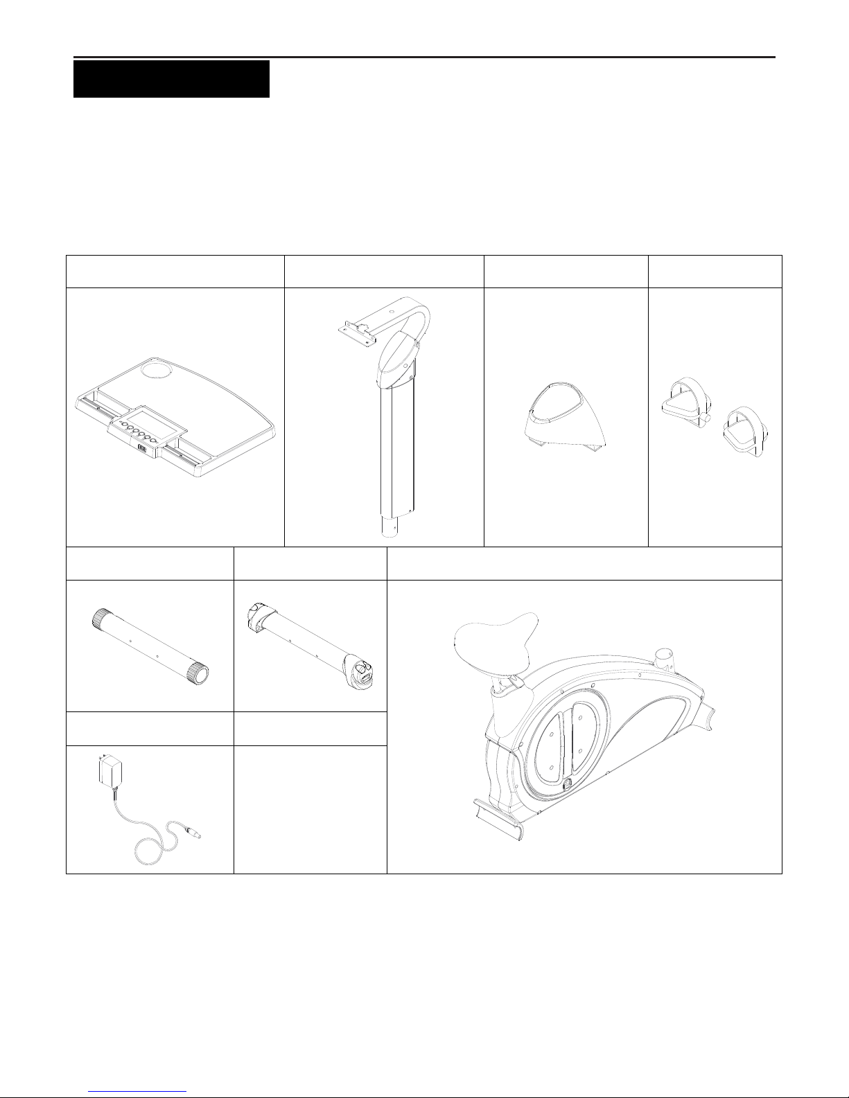
Unpack the box in a clear area. Follow the List of Assembly Parts below to check and make sure all assembly parts are
present and in good condition. Do not dispose of the packing material until the assembly process is completed. Assembly
tools and hardware kit have included for you to use when assembling the product
Console Assembly Upright Post Assembly Upright Sleeve Pedal
Front Stabilizer Rear Stabilizer
Main Frame Assembly
Adaptor
3
“HARDWARE IDENTIFICATION CHART”
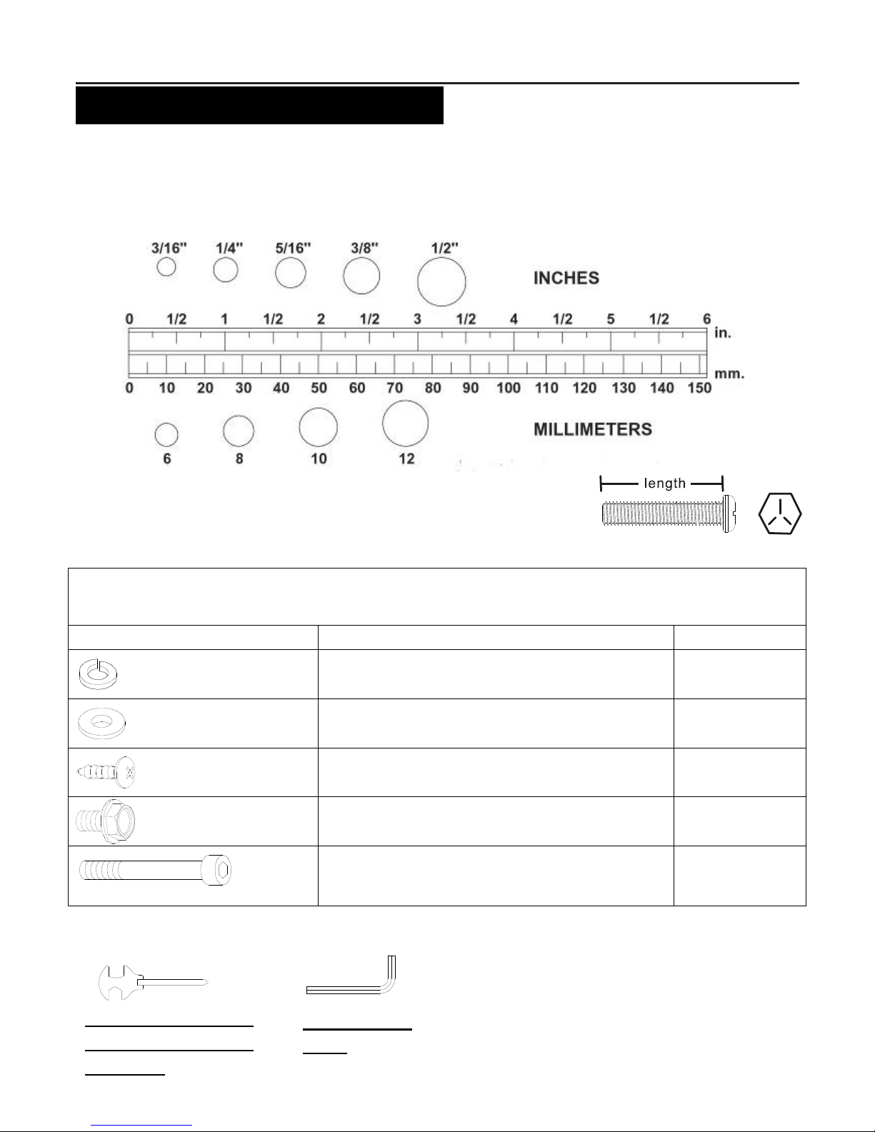
Unpack the box in a clear area. Follow the List of Hardware Kit below. This chart is provided to help identify the hardware
used in the assembly process. Place the washers, the end of bolts, or screws on the circles to check for th e correct
diameter. User the small scale to check the length of the bolts and screws. Do not dispose of the packing material until the
assembly process is completed
NOTICE: The length of all bolts and screws except those with flat heads is
Measured from below the head to the end of the bolt or screw. Flat head
bolts and screws are measured from the top of the head to the end of the
bolt or screw
After unpacking the unit, open the hardware bag and make sure that you have all the following items. Note: Some small
parts may have been pre-attached for shipping. If a part is not in the hardware bag, check to see if it has been
pre-assembled
Part No. and Description Q’TY
65 Lock Washer (M8)
8 pcs
66 Washer (8x16x2.0t)
8 pcs
69 Self-Tapping Screw, Truss Head (M4x12mm)
2 pcs
81 Bolt, Hex Flange (M8xp1.25x16mm)
4 pcs
82 Bolt, Socket Head (M8xp1.25x16mm)
84 Bolt, Socket Head (M8xp1.25x90mm)
4 pcs
4 pcs
THE FOLLOWING TOOLS ARE INCLUDED FOR ASSEMBLY:
MULTI WRENCH TOOL W/
PHILLIPS SCREWDRIVER
(13 & 15mm)
ALLEN WRENCH
(6 mm)
4
“BEFORE YOU BEGIN”
Thank you for choosing the UPRIGHT BIKE. We
take great pride in producing this quality product and
hope it will provide many hours of quality exercise to
make you feel better, look better and enjoy life to its
fullest.
Yes, it's a proven fact that a regular exercise
program can improve your physical and mental health.
Too often, our busy lifestyles limit our time and
opportunity to exercise. The equipment provides a
convenient and simple method to begin your assault
on getting your body in shape and achieving a
happier and healthier lifestyle.
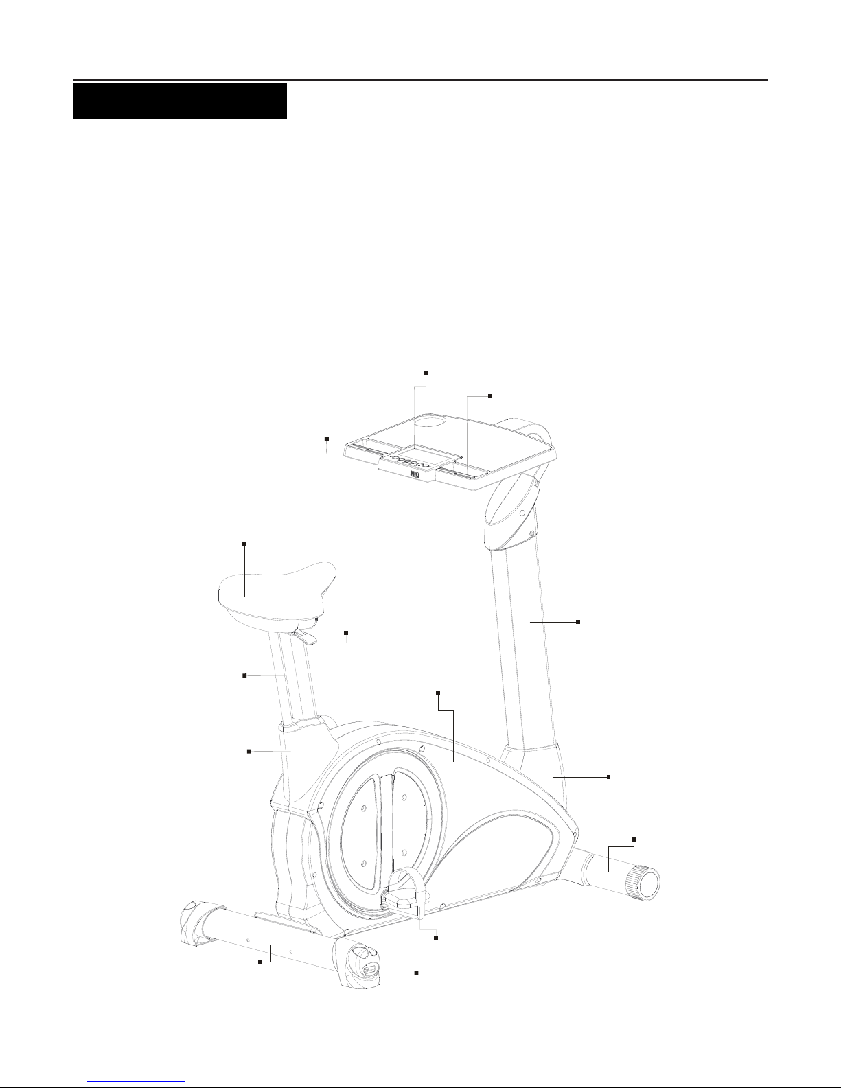
Before reading further, please review the drawing
below and familiarize yourself with the parts that are
labeled. Read this manual carefully before using the
equipment.
Console
Handlebar
Upright Post
Upright Sleeve
Seat Post
Adjusting Handle
Front Stabili zer
Pedal
Adjustable Rear S tabilizer EndCap
Seat Cushion
Seat Cap
Rear Stabili zer
Main Frame
Hand Pulse Sensor

5
“ASSEMBLE INSTRUCTIONS”
S
TEP 1
–
Stabilizer Assembly
a. Identify the correct direction of the Front Stabilizer (2), there is an “R” decal on the right side of the Front Stabilizer
(2)
b. Attach the Front Stabilizer (2) to the Main Frame (1) and secure with two Lock Washers (M8)(65), two Washers
(8x16x2.0t)(66) and two Bolts, Socket Head (M8xp1.25x90mm)(84)
c. Fully secure two Lock Washers (M8)(65), two Washers (8x16x2.0t)(66) and two Bolt s, Socket Head
(M8xp1.25x90mm)(84) that attach to the Front Stabilizer (2) to the Main Frame (1)
d. Follow the above STEP b. to attach the Rear Stabilizer (3) to the Main Frame (1) with two Lock Washers (M8)(65),
two Washers (8x16x2.0t)(66) and two Bolts, Socket Head (M8xp1.25x90mm)(84).
NOTE: “Small Tip: Attach screws and bolts to the assembly parts first before secure”
To assemble the Front Stabilizer (2) to the Main Frame (1) with more efficient and easy way, it is suggested to
attach two Lock Washers (M8)(65), two Washers (8x16x2.0t)(66) and two Bolts, Socket Head
(M8xp1.25x90mm)(84) to the Front Stabilizer (2) and the Main Frame (1) first before fully secure. **Please do
not secure the bolts unless you make sure Bolts all go into screw holes of Front Stabilizer and Main
Frame**
6
“ASSEMBLE INSTRUCTIONS”
S
TEP 2
–
Upright Post Assembly
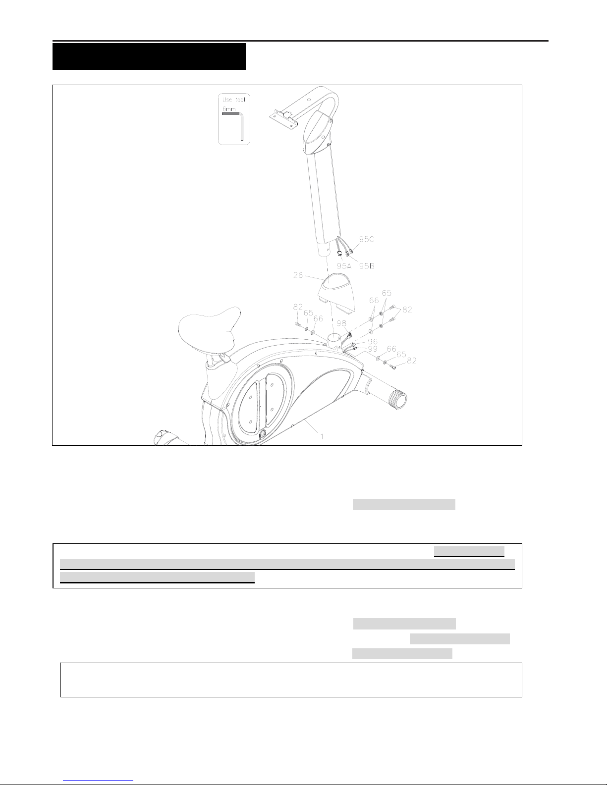
a. Slide the Upright Sleeve (26) onto the Upright Post Assembly (5). Do not pinch the wires.
b. Attach the Upright Post Assembly (5) to the Main Frame (1) with four Washers (8x16x2.0 t)(66), four Lock
Washers (M8)(65), and four Bolts, Socket Head (M8xp1.25x16mm)(82).
c. Fully secure four Washers (8x16x2.0t)(66), four Lock Washers (M8)(65), and four Bolts, Socket Head
(M8xp1.25x16mm)(82) that attach to the Upright Post Assembly (5) and the Main Frame (1).
d. Connect the Lower Connection Wire (95A) to the Motor Wire (98). Do not pinch the wires.
e. Connect the Rear Connection Wire (95B) to the Adaptor Connection Wire (96). Do not pinch the wires
f. Connect the Rear Connection Wire (95C) to the Sensor Wire (99). Do not pinch the wires
g. Slide the Upright Sleeve (26) down until it meets the Main Frame (1).
NOTE: “Small Tip: Attach screws and bolts to the assembly parts first before secure” ** Please do not
secure the bolts unless you make sure 4pcs Washers, Lock Washers and Bolts all go into screw holes
of Upright Post Assembly and Main Frame**
NOTE: After connecting the wires, slightly and gently pull two sides of wires to test and make sure whether the
wires are fully connected.
7
“ASSEMBLE INSTRUCTIONS”
S
TEP 3
–
Console Assembly
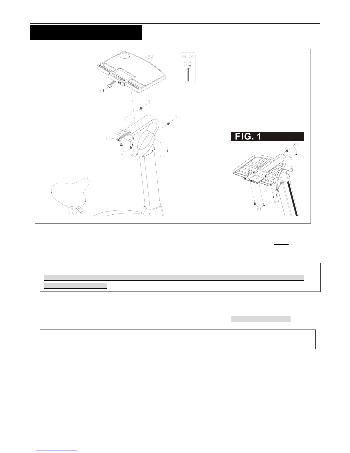
a. Place the Console Assembly (32) onto the iron plate of the Upright Post Assembly (5). Refer to FIG. 1, fix the
Console Assembly (32) with four Bolts, Hex Flange (M8xp1.25x.16mm)(81) and two Self-Tapping Screw, Truss
Head (M4x12mm)(69).
b. Fully secure four Bolts, Hex Flange (M8xp1.25x.16mm)(81) and two Self-Tapping Screw, Truss Head
(M4x12mm)(69) that attach to the Console(32,33) and the Upright Post Assembly(5).
c. Connect the Upper Connection Wire (94) to the Lower Connection Wire (95). Do not pinch the wires.
NOTE: After connecting the wires, slightly and gently pull two sides of wires to test and make sure whether the
wires are fully connected.
Small Tip: Attach ALL screws and bolts to the assembly parts first before secure.
**Please do not secure the bolts unless you make sure ALL Bolts go into screw holes of Console and
Upright Post Assembly**
8
“ASSEMBLE INSTRUCTIONS”
S
TEP
4 –
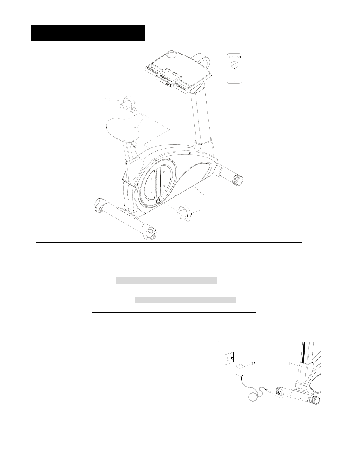
Pedal Assembly
a. Thread the Right Pedal (11) into the right crank area of the Main Frame (1). Firmly tighten the Right Pedal (11)
clockwise into the right crank. Tighten the Pedal as firmly as possible
b. Thread the Left Pedal (10) into the left crank area of the Main Frame (1). Firmly tighten the Left Pedal (10)
counter-clockwise into the left crank. Tighten the Pedal as firmly as possible
c. Finish the assembly, make sure that all parts are tightened before you use the equipment
S
TEP
5 –
AC Adaptor
a. Connect the Adaptor (97) to the connector located on the front side of
the Main Frame (1).
b. Plug the Adaptor (97) into an electrical outlet to light up the console.
 Loading...