

Orbit Silver XT Owner's Manual
Orbit
Silver XT
OWNER’S MANUAL
Part # Silver XT Rev. 09/07/2012
www.orbitfitness.com.au

TABLE OF CONTENTS
INTRODUCTION 3
ORTANT SAFETY INSTRUCTIONS
IMP
4
ASSEMBLY INSTRUCTIONS
Installation Requirements
Unpacking Your Elliptical
Tools Required for Assembly 5
Grounding Instructions
Box Contents
Hardware Legend 7
Assembly 8-16
Testing Your Elliptical
THE ORBIT SILVER XT CONTROL PANEL
OPERATING INSTRUCTIONS
Configuring User ID’s
Quick Start
Manual Workout (Timed)
FBT (Full Body Trainer)
Fat Burn Workouts 26-28
F2, F3, and F4,
Fat Burn Course Specifications
Heart Rate Workouts
Interval Workouts I1, I2, and I3
Interval Course Specifications
F1
6
23
26
5-17
5
5
5
17
18-20
21-33
21-22
24
25
27
28
29-31
32
33
EXCLUSIVE ORBIT FEATURES
Exercise Preview 34
Personal Electronic Trainer 34-35
Aerobic Points
TROUBLE SHOOTING
FREQUENTLY ASKED QUESTIONS 37
ORBIT
TECHNICAL SPECIFICATIONS 38
34
36
34-35
2

INTRODUCTION
Congratulations and thank you for choosing Orbit – your partner in achieving your fitness goals and mastering your well-being.
Orbit’s advanced digital technology allows your elliptical to process information instantly, anticipating and adjusting to meet your
needs. Think of it as your own personal trainer.
Orbit’s superior components and US design ensure we produce Ellipticals of the highest quality while also offering excellent value
for your dollar. Orbit Products have consistently received praise from a wide range of nationally recognized publications.
To get the most from your Orbit, please read this owner’s manual carefully before starting to use the elliptical. The manual contains
important information about the assembly, operation and maintenance of the mach
ine.
Please ensure you read and fully understand all safety informat
important safety warnings throughout the manual. Failure to read and understand these warnings may result in personal injury or damage
to your elliptical.
i
p indicates a useful suggestion when installing, maintaining or using your Elliptical Cross Trainer.
T
Please take the
maximum efficiency to achieve your fitness goals and master your well-being.
We wish you an enjoyable and rewarding partnership with your Orbit Elliptical Cross Trainer.
time to familiarize yourself with the range of functions available. This will help you work with your Orbit elliptical for
ion.
DANGER, CAUTION, or WARNING indicates
The Orbit Silver XT Elliptical Cross Trainer is designed for home use only.
3

IMPORTANT SAFETY INSTRUCTIONS
Read these instructions before using your Elliptical Cross Trainer
CAUTION: Before starting any exercise program, contact your personal physician and have a complete physical. This is highly
recommended if you have not been on a regular exercise program within the last year, or are over 35 years of age, or are overweight.
CAUTION: If at any time during your exercise program you find the exercise abnormally difficult or you encounter dizziness, feel
faint, experience chest pains, feel as if your heart may be skipping beats, you experience forced heavy breathing after minimal exercise or
severe pain in your legs, ankles
WARNING: To reduce the risk of burns, fire, electrical shock or injury:
• Your Orbit Elliptical is not designed for use by children under the age of 18 without strict parental supervision.
• Close supervision is necessary when the elliptical is used by or near children, disabled persons or pets.
• Use your Orbit Elliptical only for its intended use as described in this manual. Do not use accessories or attachments not
recommended by Orbit fitness.
• Never operate your Orbit Elliptical if it has a damaged cord or plug, if it is not operating properly, if it has been dropped or
damaged or if it has been immersed in water. Should any of these occur, contact your authorized Orbit retailer or service
center for examination or repair.
, knees, etc. STOP EXERCISING and consult your physician.
• Keep the cord away from heated surfaces.
• Never drop or insert any object into any opening on the elliptical.
• Do not use outdoors.
• Always unplug your Orbit Elliptical during an electrical storm or during extended periods of non-use.
• Do not operate where aerosol (spray) products are being used or where oxygen is being administered.
• Position the elliptical with a minimum of 2 feet (1219mm) of clearance between the front and rear of the elliptical and any wall or
obstruction.
• Do not allow anyone to reach under or be too near your Orbit Elliptical while it is in use.
• Never allow more than one person on your Orbit Elliptical at any time.
• Never move the elliptical while it is plugged into the electrical outlet.
• Wear appropriate shoes and attire while exercising.
4
ASSEMBLY INSTRUCTIONS
Installation Requirements
Your Orbit should be installed indoors on a flat, level surface near a 120 Volt outlet. You must have a minimum of 2 feet of
clearance between the elliptical and any wall or obstruction.
TIP: If you are installing your Orbit on a carpeted surface, use a equipment mat or a scrap piece of carpet underneath the elliptical
to avoid soiling of the carpet. Deep pile carpet is not recommended.
Unpacking Your Elliptical
The Orbit elliptical is packed in 26 pieces:
• Refer to the Parts List on the next page.
Before assembling your elliptical, open the hardware package and verify that you have the following items:
• Refer to the Hardware Legend on page 7.
If any parts are missing, contact the authorized Orbit retailer where you purchased your Orbit elliptical.
Tools Required for Assembly
17 mm wrench (2)
•
• 6 mm hex wrench
• Phillips head screwdriver
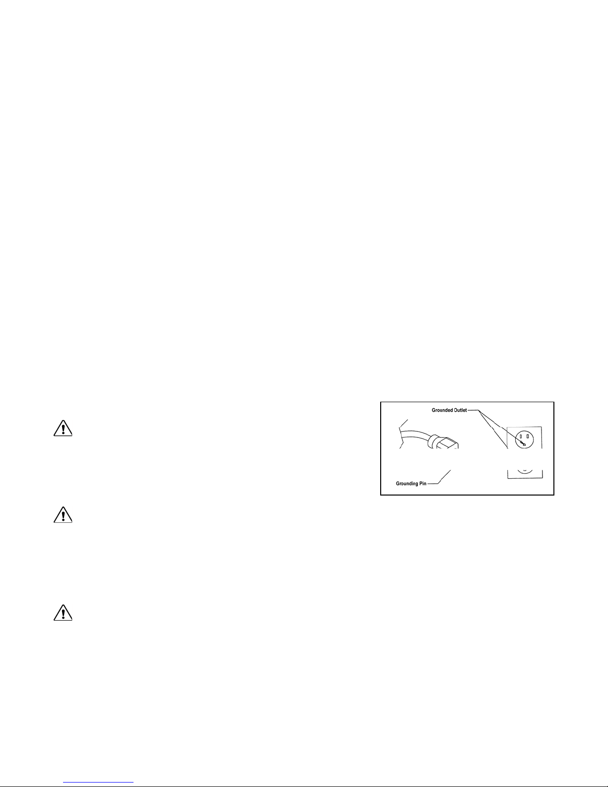
Grounding Instructions
DANGER: This product must be properly grounded. If it should malfunction or
become inoperable, grounding provides a path of least resistance for electric current to
reduce the risk of electric shock. This product is equipped with a cord having an
equipment-grounding conductor and a grounding plug. The plug must be plugged into
an appropriate outlet that is properly installed and grounded in accordance with all local
codes and ordinances. See example to the right.
WARNING: Improper connection of the equipment grounding-conductor can result in a risk of electrical shock. Check with a
qualified electrician or serviceman if you are in doubt as to whether the product is properly grounded. Do not modify the plug provided with
the product. If it will not fit the outlet, have a proper outlet installed by a qualified electrician. This product is for use on a circuit having a
nominal rating of 120 volts. It is factory equipped with a specific electric cord and plug to permit connection to a proper electric circuit.
o adapter should be used with this
Make sure that the product is connected to an outlet having the same configuration as the plug.
product. Attempting to bypass it with an adapter or in any way defeating its purpose can result in a serious shock hazard.
As a safety precaution, unplug t
CAUTION: If you need to use an extension cord it must be a 14 gauge, three wire cord, no longer than 12 feet.
he elliptical during electrical storms or if the elliptical will not be in use for periods greater than one week.
N
5
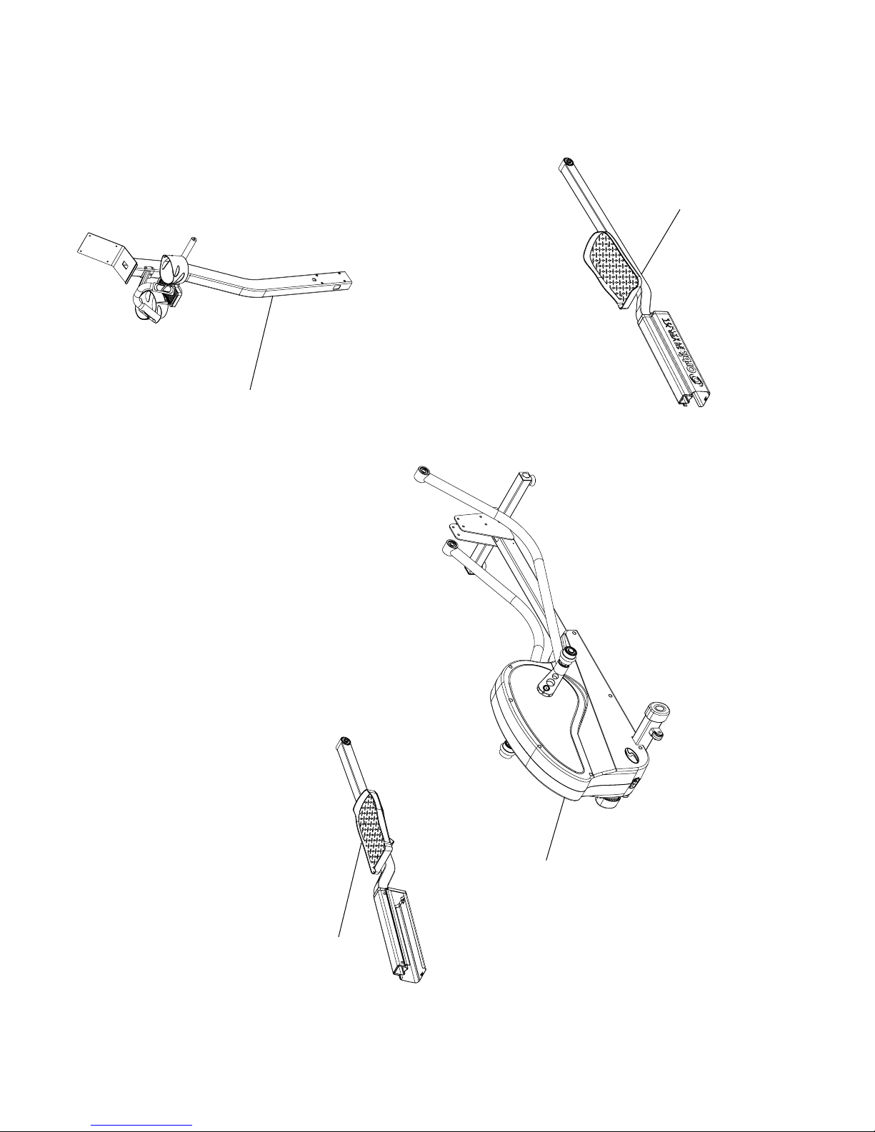
Console Mast
Assembly
Right Foot Link
Assembly
Parts List
Orbit Silver XT
Left Foot Link
Assembly
Frame Assembly
Orbit Silver XT
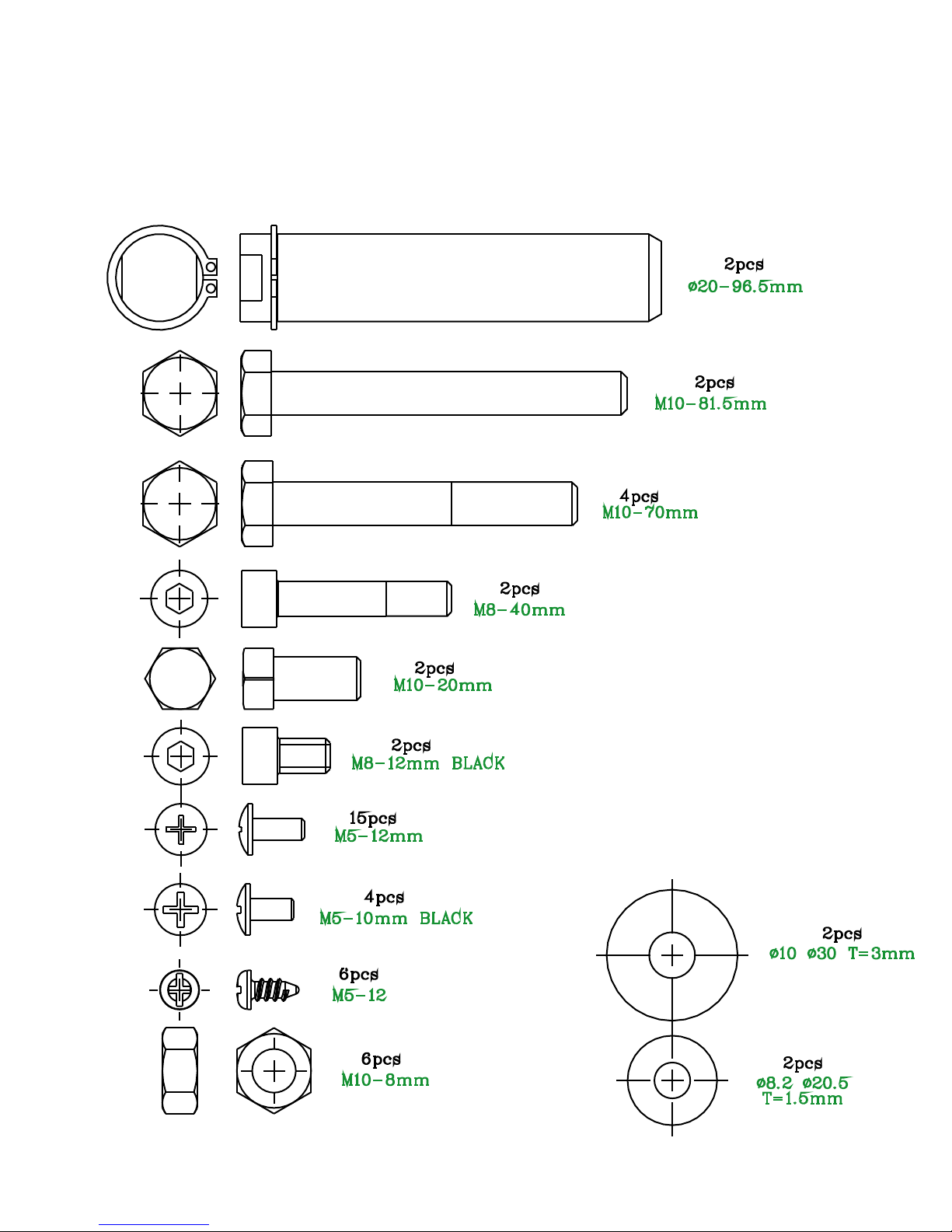
Hardware Legend
A
B
C
D
E
F
G
H
I
K
J
L
7
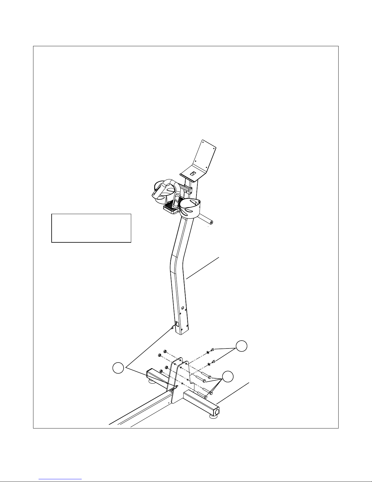
ASSEMBLY INSTRUCTIONS
STEP 1: Loosley install the 2 screws 'F' with the 2 washers 'L'.
STEP 2: Loosley install the 4 bolts 'C' with 4 nuts 'J'.
CAUTION: Do not pinch the Mast wire when installing the 4 bolts 'J'
STEP 3: Plug the Base wire into the Mast wire (make sure you stuff the extra wire
into the Mast to ensure there will be enough wire at the top when installing the control
panel). Tighten the 2 screws 'F', then tighten bolts 'J' (installed in Steps 1 & 2)
Note: Refer to Hardware
Legend on Page 7 for
fastene
r details.
3
Mast
2
1
Base
8
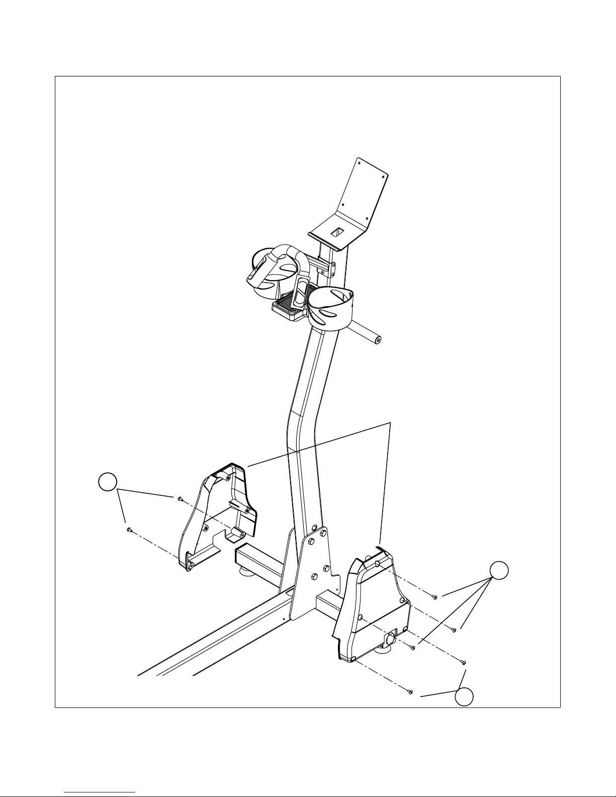
ASSEMBLY INSTRUCTIONS
STEP 4: Position and secure both pieces of the Mast Cover using 3 screws 'G'
STEP 5: Secure the assembled Mast Cover to the Base using 4 screws 'G'
Mast Cover
55
4
5
9
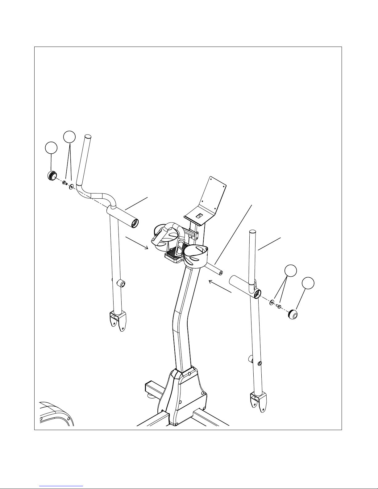
ASSEMBLY INSTRUCTIONS
STEP 6: Slide the Right Arm onto the shaft as indicated below. Secure the right arm to the
shaft using bolt 'E' and washer 'K'. Repeat this procedure for the Left Arm.
STEP 7: Install the end caps for both arms.
6
7
Left Arm
Shaft
Right Arm
6
7
10
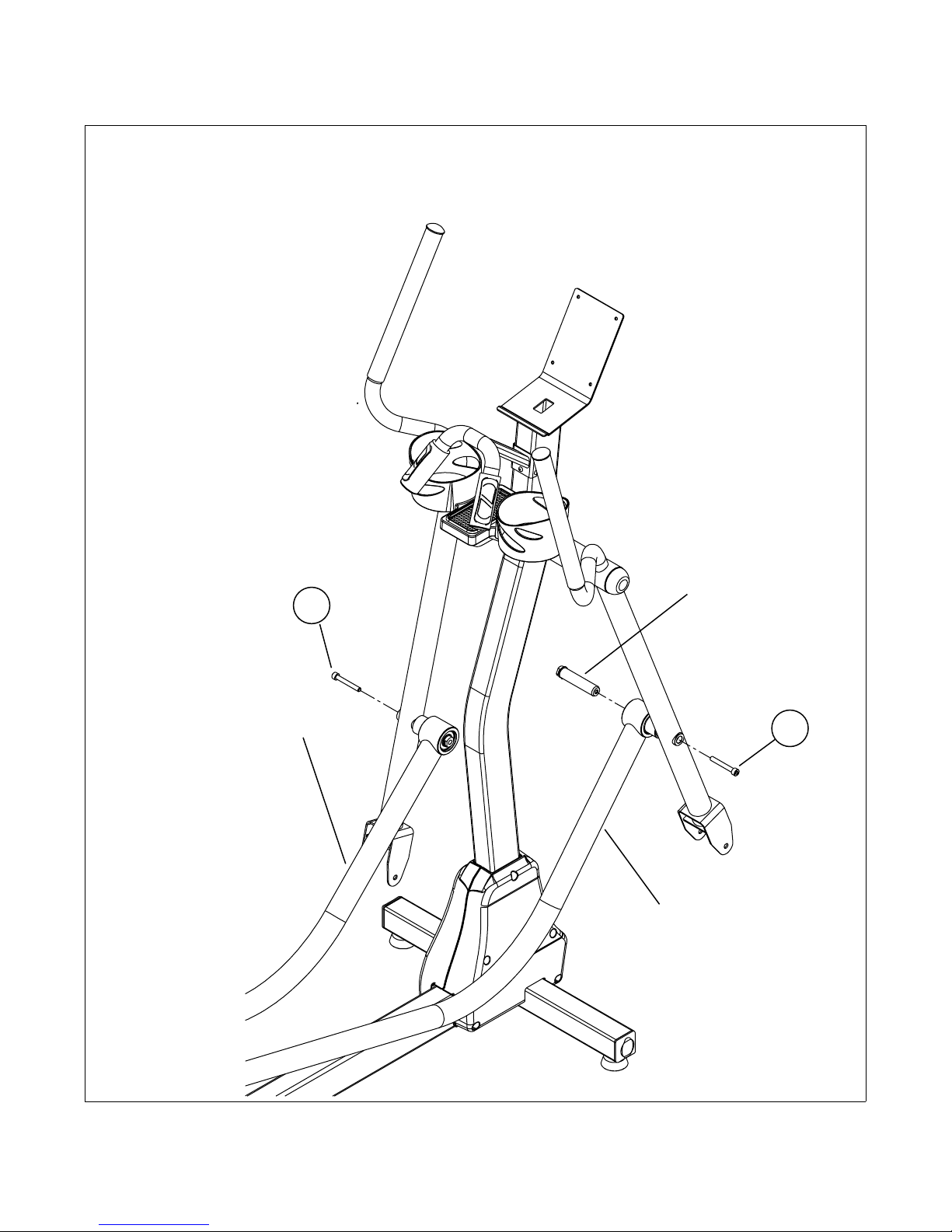
ASSEMBLY INSTRUCTIONS
STEP 8: Insert the Link shaft through the Right link and into the hole on the Right arm as
indicated below. Use screw 'D' to secure the link shaft. Perform the same procedure for the
Left link
Left Link
Link Shaft
8
8
Right Link
11
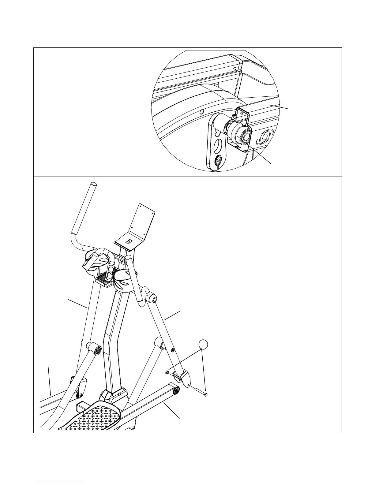
ASSEMBLY INSTRUCTIONS
STEP 9: Slide the Right Foot Link on to
the Right Foot Link Roller, as shown
to the right, making sure the convex
hump on the roller is centered with
the concave portion of the square
tube.
Right Foot Link
Right Foot Link Roller
STEP 10: Attach the Right Foot Link
to the Right Arm using Bolt 'B' and Nut 'J'
as shown below. Repeat steps 9 & 10
for the Left side.
Left Arm
Left Foot Link
Right Arm
10
Right Foot Link
12
 Loading...