

Page 1
OBE655T
Elliptical Cross Trainer
Owner’s Manual
23
OBE655T
Page 2

Table of Contents
Product Safety Page.01.............................................................................
Trouble Shooting & Maintenance & Warm Up ............... Page.12
Assembly ...................................................................................... Page.04
Hardware & Tools ...................................................................... Page.03
Computer ....................................................................................... Page.13
Part List ........................................................................................... Page.24
Part Drawing & Box A/B Contents ....................................... Page.02
Exploded View ............................................................................ Page.25
Page 3

Product Safety
Basic precautions should always be followed, including the following safety instructions
when using this equipment: Read all instructions before using this equipment.
1. Read all the instructions in this manual and do warm up exercises before using this equipment.
2. Before exercise, in order to avoid injuring your muscles, warm-up exercise for every muscle
group is highly recommended. Please refer to the Warm Up pages for pre and post workout.
3. Please make sure all components are not damaged and in working order before use. This
equipment should be placed on a flat surface while in use. Using a mat or other material on
the ground is recommended.
4. Please wear proper clothes and shoes when using this equipment; do not wear clothes that
might catch in any part of the equipment.
5. Do not attempt any maintenance or adjustments other than those described in this manual.
Should any problems arise, discontinue use and consult an Authorized Service Representative.
6. Be careful when stepping on or leaving the pedals. Always hold the handlebars first and make
sure the pedal at your side is at its lowest position. Step on the pedal, and stride over the main
frame then step on the other pedal. When using, please hold onto the handlebars. To ensure
the pedals run smoothly push or pull on the handlebars first, then follow with leg motion.
When stepping off the machine, make sure one pedal is at its lowest position and step out of
there before stepping out of the pedal at the highest position.
7. Do not use the equipment outdoors.
8. This equipment is for household use only.
9. Only one person should be on the equipment while in use.
10. Keep children and pets away from the product while in use. This machine is designed for
adults only. If you feel any chest pains, nausea, dizziness, or short of breath, you should stop
exercising immediately and consult your physician before continuing.
11. If you feel any chest pains, nausea, dizziness, or short of breath, you should stop exercising
immediately and consult your physician before continuing.
12. The maximum weight capacity for this product is 330 lbs/150 kgs.
Before beginning any exercise program consult your physician.
This is especially important for the persons who are over 35 years
old or who have pre-existing health problems. Read all instructions
before using any fitness equipment.
WARNING:
CAUTION:
Read all instructions carefully before operating this product.
Retain this Owner’s Manual for future reference.
1
Page 4
2
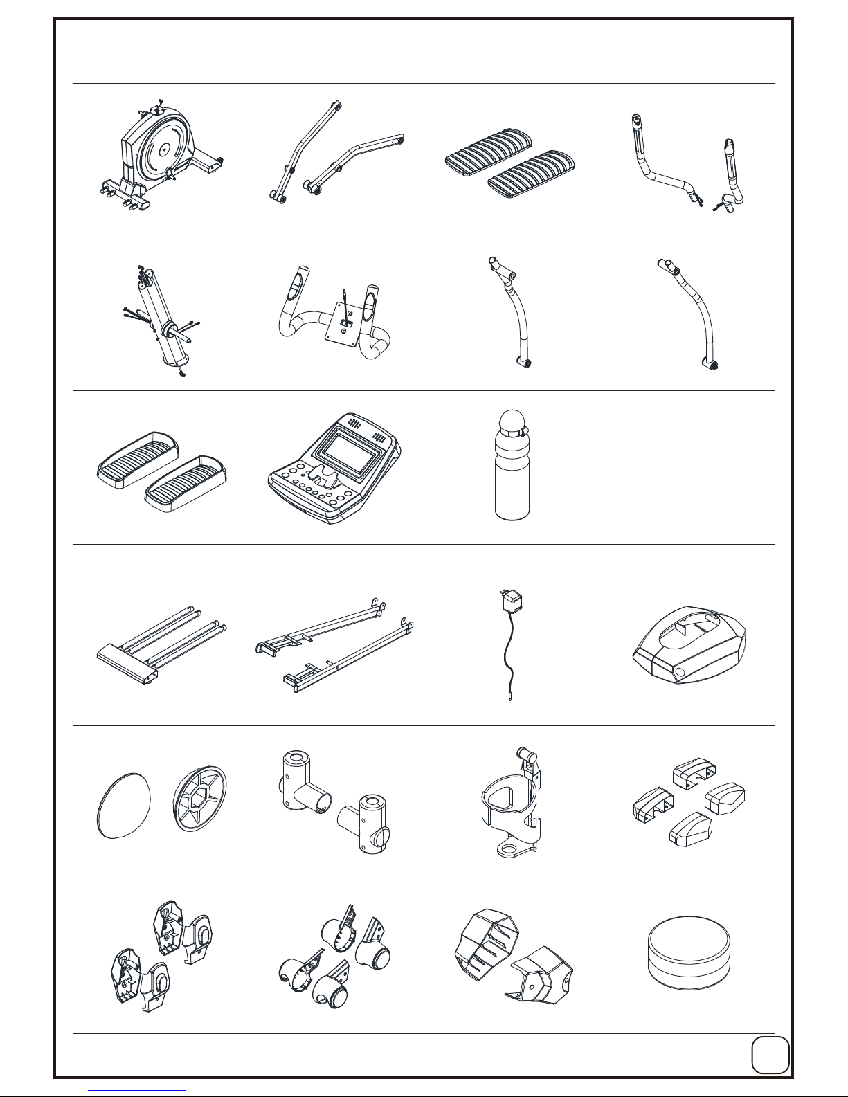
Part Drawing & Box A/B Contents
A01 A07/A08 A13/A14
A02
MainBody
Left/Right
Wheel Bar Set Handrails
Front Post
1PC 1Set 1Set
1PC
Computer
Left
Dual Action Arm Set
Right
Dual Action Arm Set
Foot Pedal
1PC
1Set 1Set
2PCs
A15 A03 A04
C12
A12 A05/A06 D08 C07/C08
C11
Guide Rail
Left/Right
Foot Pedal Bar Set AC Adaptor
Left/Right Front Post
Decorative Covers
Nut Cap
1PC 1Set 1PC 1Set
2PCs
Handrail Arm
Decorative Covers-A/B Bottle Holder
Left/Right
D Shape End Cap
Left/Right Pivot Cap
2Sets 1PC 2Sets
2Sets
C17/C18 C27 C28/C29
Box B
Box A
Hand Pulse Handlebar 1PC
Left/Right Wheel Cap 2Sets Lubricant 1PC
D02
C34
Foot Pedal Pad 1Set
C30/C31 C32/C33
Water Bottle 1PC
Pivot Cap
For Crank Link Tube 2PCs
C35
Page 5
3
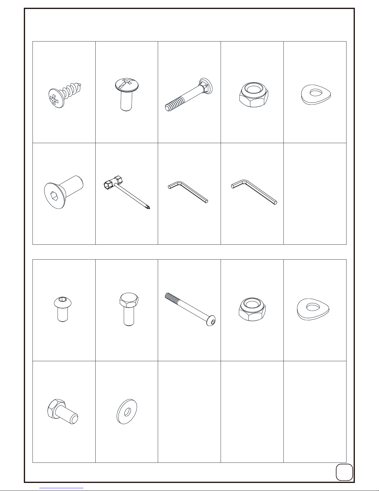
Hardware & Tools
B32 (2) B33 (7)
B21 (5)
B40 (7)
B28 (1)
Hexagon Head Bolt
M8x16mm
Washer
5/16”x20x2.0t
Screw M5x16mm
Bolt M8x25mm
6PCs 8PCs
30PCs
2PCs
Bolt M8x50mm 4PCs
B29 (3) B30 (4)B23 (2)
Nylon Nut M8Bolt M6x15mm 4PCs8PCs
Curve Washer
M8x20x1.5t 4PCs
Hex Tool With
Phillips Screwdriver
(13mm/14mm) 1PC Allen Wrench (M5) 1PCAllen Wrench (M4) 1PC
B24 (1)
Bolt M8x92mm 2PCs
B13 (6) B14 (3)
Bolt M8x16mm 16PCs Bolt M8x20 4PCs
B30 (4)
Curve Washer
M8x20x1.5t 16PCs
B29 (5)
Nylon Nut M8 2PCs
Pack A
Pack B
(8) (9)(6)
Page 6
4
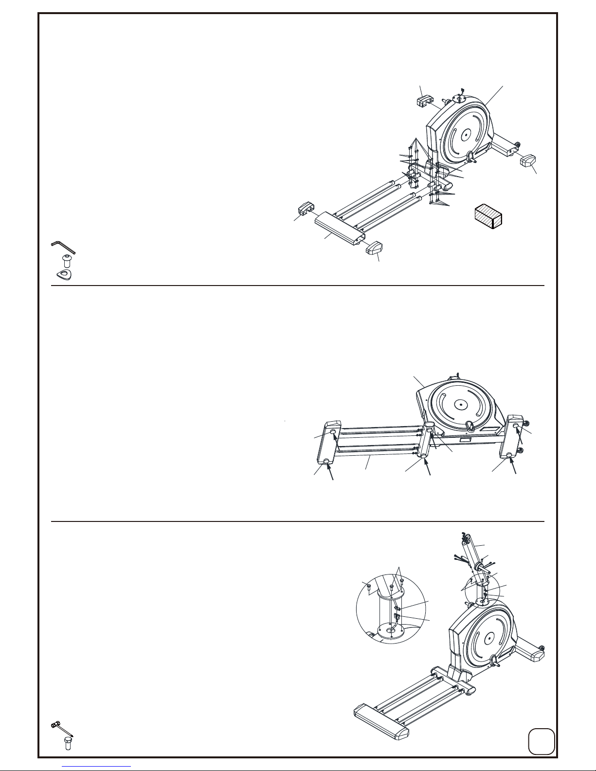
Assembly
1. Guide Rail Installation
2. Adjusting the Adjustable Leveler
Turn the Adjustable Levelers (C05) on the MainBody (A01) and Guide Rail (A12) as needed to level the
elliptical trainer.
The elliptical trainer has to be leveled to prevent from wobbling or shaking during the exercise.
3. Front Post Installation
Connect the Extension Sensor Wire II (D05) from the MainBody (A01)
to the Extension Sensor Wire I (D04) from the Front Post (A02) and
carefully tuck the wires into the MainBody (A01) before attaching
the Front Post (A02) onto the MainBody (A01).
Attach the Front Post (A02) onto the MainBody (A01) and fully
tighten with 4 Bolts (B14).
[Tighten bolts with the
Hex Tool With Phillips Screwdriver provided]
For easier installation of the Guide Rail (A12), place a block of wood under the
MainBody (A01).
Attach the Guide Rail (A12) onto the tubes of the MainBody (A01) with
16 Bolts (B13) and 16 Washers (B30) that were removed.
Assemble the Left and Right D Shape End Cap(C28/C29) into the tube of the
MainBody(A01) and Guide Rail (A12).
[Remove/Tighten bolts with the M5 Allen Wrench provided]
M5 Allen Wrench
Hex Tool With Phillips Screwdriver (13mm/14mm)
C29
C28
A12
B30
B30
B30
B30
B13
B13
C29
C28
A01
B13
B30
B13
C05
C05
C05
C05
C05
C05
A12
A01
Adjusting the Adjustable Leveler
A02
B14
B14
B14
D05
D04
B14
B14
D05
D04
block of wood
1.)
2.)
3.)
1.)
1.)
2.)
(B13)Bolt M8x16mm---16PCs
(B30)Washer M8x20x1.5t---16PCs
(B14)Bolt M8x20mm---4PCs
Page 7
Assembly
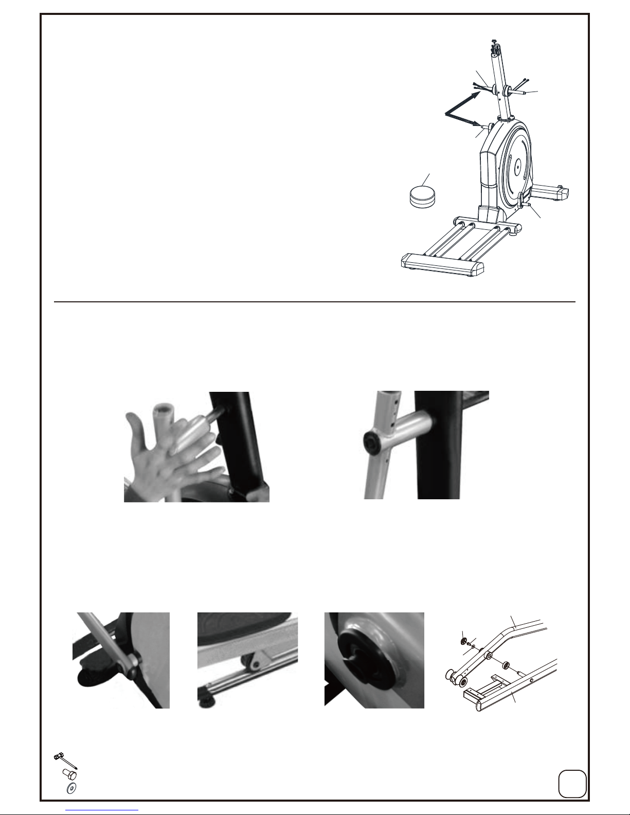
4. Lubricating the Horizontal Axle and Crank Axle
Apply lubricant to the horizontal axles of the Front Post (A02)
and the axles of the right and left Crank (A11).
5. Left and Right Foot Pedal Linkbar Installation
5
Remove the tape from the joint of the Right Dual Action Arm Set (A04).
Insert the Right Dual Action Arm Set (A04) all the way onto the horizontal axle of the Front Post (A02) and secure
the Right Dual Action Arm Set (A04) in position with 1 Bolt (B32) and 1 Washer (B33).
[Tighten bolt with the Hex Tool with Phillips Screwdriver provided]
Remark: Gently apply lubricant evenly on Front Post (A02).
Brush tool is recommended.
Hex Tool With Phillips Screwdriver (13mm/14mm)
(B33)Washer 5/16”x20x2.0t---6PCs
(B32)Bolt M8x16mm---6PCs
Lubricant
A02
A02
A11
A11
10
Lubricating the
horizontal axle
and crank axle.
Remove the tape from the joint of the Right Wheel Bar Set (A08).
Insert the Right Wheel Bar Set (A08) onto the Crank (A11) axle.
The Wheel (C20) has to be placed on the Rail Aluminum Plate (F01).
Secure the Right Wheel Bar Set (A08) in position with 1 Bolt (B32) and 1 Washer (B33).
Insert the axle of the Right Foot Bar Set(A06) onto the Right Wheel Bar Set(A08), secure the Right Foot
Bar Set(A06) in position with 1 Bolt (B32) and 1 Washer (B33).
[Tighten bolt with the Hex Tool with Phillips Screwdriver provided]
CAUTION: Make Sure The Bushing Spacer (B41) Was Perfectly In Position Before Securing
The Bolts.
1.)
2.)
3.)
4.)
5.)
6.)
C11
B32
B33
A08
A06
Page 8
Assembly
6
Hex Tool With Phillips Screwdriver (13mm/14mm)
A06
A04
A08
B24
B33
B29
M8x45 Nut Cap (C11)
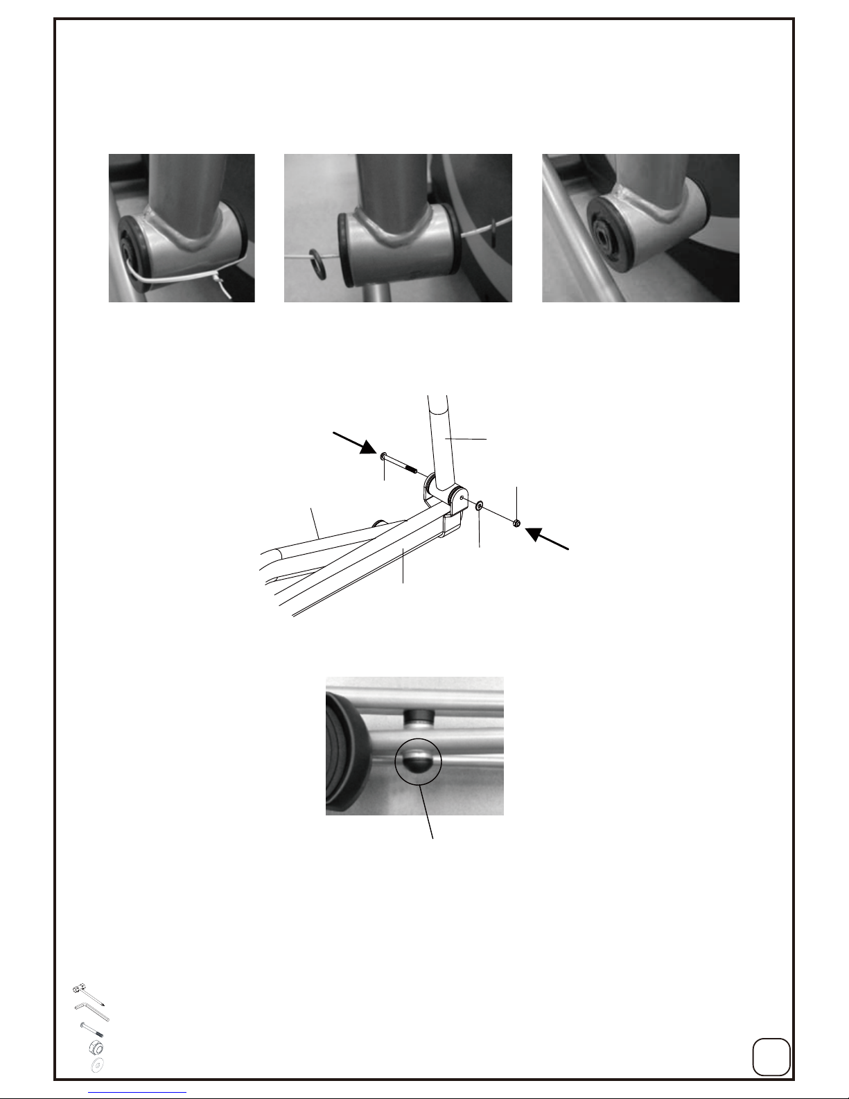
Untie the wire and remove 2 Washers (C22) from the bottom end of the Right Dual Action Arm Set (A04).
Place 2 Washers (C22) back onto the joint of the Right Dual Action Arm Set (A04).
Pull the Right Foot Bar Set (A06) up onto the Right Dual Action Arm Set (A04) and align bolt holes.
Then attach the Right Foot Bar Set (A06) onto the Right Dual Action Arm Set (A04) with 1 Bolt (B24),
1 Nut (B29), and 1 Washer (B33) that were removed.
[Tighten bolt and nylon nut with the Hex Tool with Phillips Screwdriver and M5 Allen wrench provided]
Repeat above steps to install the Left Dual Action Arm Set (A03) onto the horizontal axle of the Front
Post (A02) and Left Wheel Bar Set (A07) onto the Crank (A11) axle.
Fit one Nut Cap (C11) onto M8x16mm Hexagon Head Bolts (B32) of the Right Rotate Bar (A08).
7.)
8.)
M5 Allen Wrench
9.)
Remark: Please use the assembly drawings of steps No. 1-9 at Page No. 7.
(B33)Washer 5/16”x20x2.0t---2PCs
(B29)Nut M8xP1.25x7.7t---2PCs
(B24)Bolt M8x92mm---2PCs
Page 9
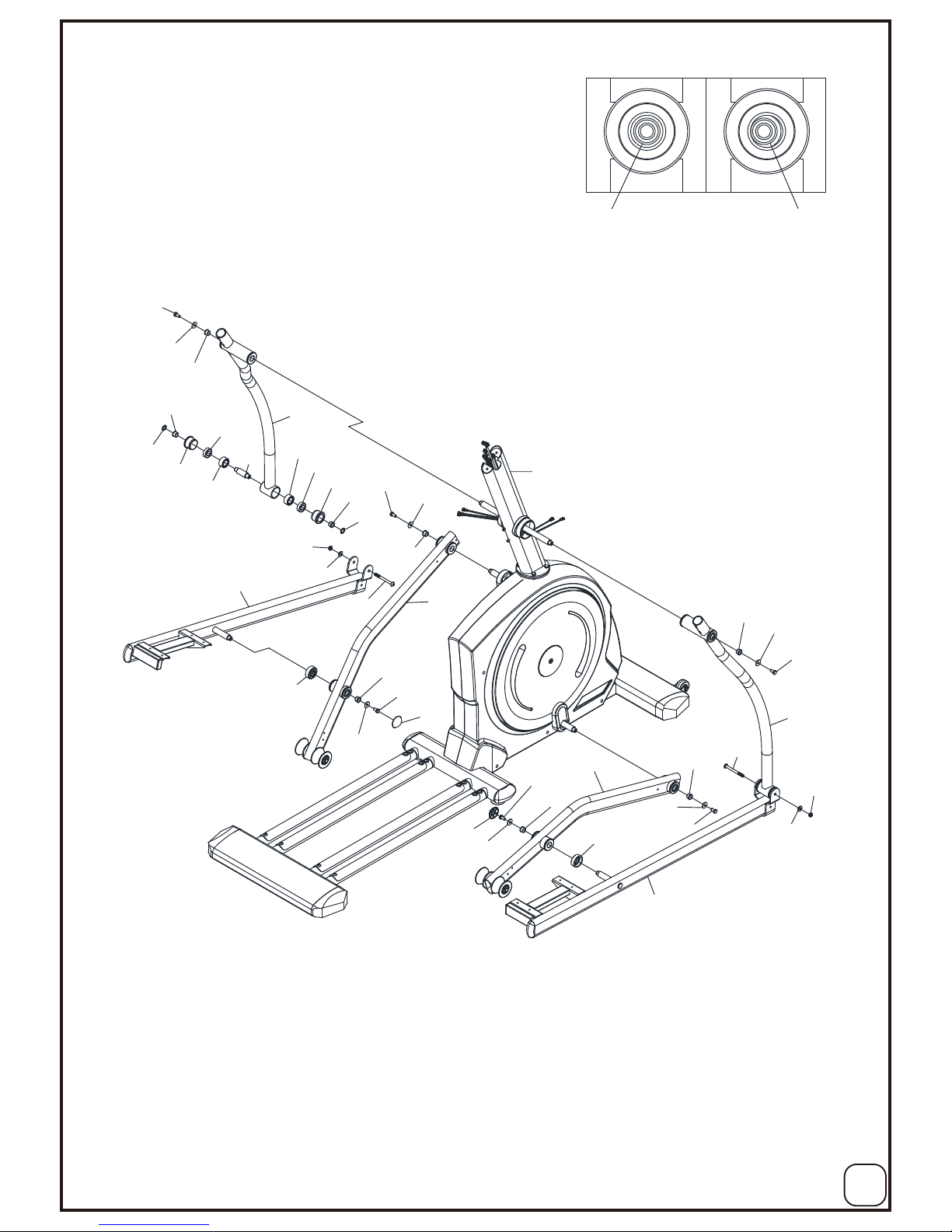
Assembly
7
A07
C23
B41
B33
B32
C11
B32
B33
B41
C11
B32
B33
B41
C23
A08
B41
B33
B32
A04
A06
B24
B33
B29
B32
B33
B41
A02
A05
A03
B32
B33
B41
C25
E02
E02
C25
C24
C24
B31
C22
C22
B41
B41
B24
B29
B33
INCORRECTCORRECT
B41 B41
Page 10

Assembly
6. Pivot Covers Assembly
Assemble two sets of Pivot Cover(C30/C31) at the pivot of Left and Right Dual Action Arm(A03/A04) and
Foot Pedal bar(A05/A06) with 8 Screws(B21).
Assemble two pcs of Pivot Cover for Crank Link(C35) to the pivot of Right/Left Wheel Bar Set(A08/A07) and
Crank(A11) using 4 Screws (B21).
Assemble two sets of Wheel Caps(C32/C33) to the wheel of the Left and Right Wheel Bar Set(A07/A08) with
8 Screws(B21).
[Tighten bolts with the Hex Tool With Phillips Screwdriver provided]
8
Hex Tool With Phillips Screwdriver (13mm/14mm)
(B21)Screw M5x16mm---20PCs
C33
C32
C32
C33
B21
B21
B21
B21
B21
B21
C35
C35
C31
C30
C30
C31
B21
B21
1.)
2.)
3.)
A04
A04
A03
A07
A08
Page 11

9
Assembly
7. Hand Pulse Handlebar Installation
8. Right/Left Handrails Installation
Connect All plugs of cabel of Right/Left Quick Key(D17/D18)
and Big Hand Pulse(D15).
Slide the Left and Right Handrails(A13/A14) into the Dual
Action Tube.
Use 4 Bolts(B28), 4 Washers(B30) and 4 Nuts(B29).
[Tighten nylon nuts with the Hex Tool with Phillips Screwdriver
provided]
9. Handrail Arm Decorative Covers-A/B Installation
Attach the Handrail Arm Decorative Cover-A (C17) and Handrail Arm
Decorative Cover-B (C18) onto the Left Handrail Arm (A03) with
4 Screws (B21).
Attach the Handrail Arm Decorative Cover-A (C17 and Handrail Arm
Decorative Cover-B (C18) onto the Right Handrail Arm (A04) with
4 Screws (B21).
[Tighten bolts with the Hex Tool with Phillips Screwdriver provided]
Slide all computer cables(D04)(D15 x 2 )(D17/D18) through the slot of
Hand Bar Post (A15), use 2 Bolts (B40) to assemble the Hand Bar
Post to the Upright Support Post(A02).
[Tighten bolts with the M5 Allen Wrench provided]
(B40)Bolt M8x25mm---2PCs
(B28)Bolt M8x50mm---4PCs
Hex Tool With Phillips Screwdriver (13mm/14mm)
(B21)Screw M5x16mm---8PCs
B40
B40
A02
D10
D04
D15
D15
D18
D17
A15
B28
B28
B30
B30
B29
B29
D15
D15
D18
D15
D18
D15
D18
D15
D17
A13
A14
D18
Allen Wrench
1.)
1.)
2.)
(B29)Nylon Nut M8x7.7t---4PCs
(B30)Curve Washer M8x20x1.5t---4PCs
Hex Tool With Phillips Screwdriver (13mm/14mm)
C17
C18
B21
B21
B21
B21
C18
C17
1.)
2.)
D17
A04
A03
Page 12

10
Assembly
10. Left/Right Front Post Decorative Covers Installation
11. Foot Pedal & Pedal Pad Installation
Use 8 Bolts(B23) to assemble the Left and Right Foot Pedal(C12).
Peel off the plastic cover of the foam tape under the Cushion Pad(C34)
and attach the Cushion Pad to the Foot Pedal(C12).
[Tighten bolts with the Hex Tool with Phillips Screwdriver provided]
Attach the Left/Right Front Post Decorative Covers (C07/C08) onto the
Front Post (A02) with 2 Screws (B21).
[Tighten bolts with the Hex Tool with Phillips Screwdriver provided]
(B23)Bolt M6x15mm---8PCs
C07
C08
B21
1.)
1.)
2.)
C12
C12
B23
B23
B23
B23
C34
C34
C27
B15
B15
12. Bottle Holder Installation
Remove 2 Bolts (B15) from the Front Post (A02).
Attach the Bottle Holder (C27) onto the Front Post (A02) with
2 Bolts (B15) that were removed.
[Remove/Tighten bolts with the M4 Allen Wrench provided]
M4 Allen Wrench
(B21)Screw M5x16mm---2PCs
Hex Tool With Phillips Screwdriver (13mm/14mm)
Hex Tool With Phillips Screwdriver (13mm/14mm)
1.)
2.)
A02
A02
Page 13

11
Assembly
14. AC Adaptor Installation
13. Computer Installation
Remove 4 Screws (B17) from the back of the Computer (D02).
Connect the Extension Sensor Wire I (D04), Hand Pulse Sensor Wire (D10),
Left/Right Quick Key Extension Wire (D17/D18), and Big Handpulse Sensor Wire (D15) to the wires that come
from the Computer (D02) and then attach the Computer (D02) onto the top end of the Hand Pulse Handlebar
(A15) with 4 Screws (B17) that were removed.
[Remove/Tighten bolts with the Hex Tool with Phillips Screwdriver provided]
Plug the AC Adaptor (D08) into the power jack of the Power
Supply Cable (D09) on the front of the Main Frame (A01).
Make sure the specifications of power supply on the Adaptor
is correct before pulg in.
Plug the other end of the AC Adaptor (D08) into the electrical wall
outlet.
D02
B17
D10
D04
D17
D18
D15
D15
1.)
2.)
1.)
2.)
D08
D09
A01
Hex Tool With Phillips Screwdriver (13mm/14mm)
A15
Page 14

12
Trouble Shooting
Computer not working correctly
Check to make sure the computer cable is connected securely.
Make sure the batteries are installed correctly.
Make sure the batteries are not dead.
The elliptical trainer wobbles when in use
Turn the adjustable leveler on the front stabilizer, main frame, or U shape rail as needed to level the
elliptical trainer.
Squeaking noise when in use
The bolts may be loose on the elliptical trainer, please inspect the bolts and tighten the loose ones.
No, inconsistent, or erratic heart rate reading
Always hold on to the handlebar grip sensors with two hands instead of just one.
Try to maintain moderate pressure while holding onto the hand pulse sensors.
Make sure that the wire connections for the hand pulse sensors are secure.
Cleaning
The elliptical trainer can be cleaned with a soft cloth and mild detergent. Do not use abrasives or
solvents on plastic parts. Please wipe your perspiration off the elliptical trainer after each use.
Be careful not get excessive moisture on the computer display panel as this might cause an electrical
hazard or electronics to fail. Please keep the elliptical trainer, specially, the computer console,
out of direct sunlight to prevent screen damage. Please inspect all assembly bolts and pedals on the
machine for proper tightness every week.
Storage
Store the elliptical trainer in a clean and dry environment away from children.
Maintenance
Warm Up
Quadriceps Stretch
With one hand against a wall for balance, reach behind you and pull
your right foot up. Bring your heel as close to your buttocks as possible.
Hold for 15 counts and repeat with left foot up.
Inner Thigh Stretch
Sit with the soles of your feet together with your knees pointing outward.
Pull your feet as close into your groin as possible.
Gently push your knees towards the floor. Hold for 10 counts.
Toe Touches
Slowly bend forward from your waist, letting you back and shoulders
relax as you stretch toward your toes.
Reach down as far as you can and hold for 15 counts.
Hamstring Stretches
Sit with your right leg extended. Rest the sole of your left foot against
your right inner thigh. Stretch toward your toe as far as possible.
Hold for 15 counts Relax and then repeat with left leg extended.
Page 15

13
Owner’s Manual of 81586 Monitor
Display
The monitor is designed for programmable magnetic bike and elliptical trainer and introduced with the
following categories:
- Key Functions
- Displays
- Operating Ranges
- Notice Before Exercise
- Operation Instructions
Key Functions
There are total 7 keys including UP, DOWN, ENTER/MODE, START/STOP, PULSE AND MODE.
A. UP (▲): Selects or increases the values of PROGRAMS, SEX, TIME, HEIGHT, WEIGHT, WATT,
CALORIES, TARGET HEART RATE, AGE, DISTANCE and 10 columns.
B. DOWN (▼): Selects or decreases the values of PROGRAMS, SEX, TIME, HEIGHT, WEIGHT, WATT,
CALORIES, TARGET HEART RATE, AGE, DISTANCE and 10 columns.
C. ENTER/MODE: ENTER :Chooses the functions from PROGRAMS, SEX, TIME, HEIGHT, WEIGHT,
WATT, CALORIES, TARGET HEART RATE, AGE, DISTANCE and 10 columns. The chosen function
shall flash. Please note that not all the functions can be selected in every program according to the
types of each program. MODE: Changes the display of the values between CALORIES or WATT,
DISTANCE or ODO and SPEED or RPM.
D. ST/SP: Start/Stop, Starts or stops the program chosen. And, keep pressing for 2 seconds to reset
the monitor.
E. PROGRAM: Press this button to select program function quickly, each press can select program in
order as program 1. 6. 11. 16. 21. 26. 31. 36. 41 and 46.
F. RECOVERY: Starts the function of PULSE RECOVERY.
G. MP3 FUNCTION KEYS
Page 16

14
Display
A. START: Indicates the program selected has started.
B. STOP: Indicates the program selected has stopped. And, users are free to change the programs
and the value of functions applied.
C. PROGRAM: Indicates the programs selected from PROGRAM 1 to PROGRAM 50.
D. LEVEL: Indicates the level of loading selected from LEVEL 1 to LEVEL 16.
E. GENDER: Indicates the sex (Male or Female) selected.
F. TIME/HEIGHT/WEIGHT Display: Indicates only 1 value of TIME, HEIGHT, or WEIGHT displayed
depending on the programs.
G. DIST/COUNT/ODO/FAT%: Indicates only one value of DISTANCE or COUNT or ODO or FAT%
displayed depending on the programs.
H. RPM: Indicates the value of RPM and SPEED.
I. CAL/WATT/BMR Display: Indicates only one value of CAL, WATT, or BMR displayed depending on
the programs.
Page 17

15
J. TARGET H.R./AGE/BMI/FAN Display: Indicates only one value of TARGET HEART RATE, BMI, or
AGE displayed depending on the programs. The FAN icon will be displayed on LCD when the fan
function is turned on.
K. HEART RATE/BODY TYPE /WIFI Display: Indicates only one value of HEART RATE or BODY TYPE
displayed depending on the programs. The WiFi icon will be displayed on LCD when the WiFi function
is connected.
L. LOADING Profiles: There are 10 columns of loading bars, and 16 bars in each column. Each
column represents 3 minutes workout (without the change of TIME value), and each bar represents 2
levels of loading.
Operating Ranges
Values
Range (Count up)
Count down
Preset
Increment
(Decrement)
PROGRAM
1 ~ 60
60 ~ 1 1 1
LEVEL
1 ~ 16
16 ~ 1
N/A
1
GENDER
Male, Female
N/A
Male
N/A
TIME
0:00 ~ 99:59
99:00 ~ 0:00
0:00
1:00
HEIGHT (cm)
110.0 ~ 250
250 ~ 110.0
175.0
0.5
WEIGHT (kg)
10.0 ~ 200
200 ~ 10.0
70.0
0.2
SPEED
1 ~ 999
999 ~ 1 0 1
WATT
10 ~ 400
400 ~ 10
100
5
CALORIES
0 ~ 9990
9990 ~ 0
0
10
TARGET H.R.
60 ~ 220
220 ~ 60
90
1
AGE
10 ~ 99
99 ~ 10
30
1
Things You Should Know Before Exercising
A. The values calculated or measured by the computer are for exercise purpose only, not for medical
purpose.
B. Programs Selection:
Page 18

16
There are 60 programs as 1 Manual Program, 49 Preset Programs, 1 Body Fat Program, 4 Heart
Rate Control Programs, 4 User Setting Programs, 1 WATT Control Program.
C. Program Graph:
Each graph shown is the profile of the loading in each interval (column). With the value of TIME
counting up, each interval is 3 minutes that all the columns make up 30 minutes. With the value of
TIME counting down, each interval is the value of setup TIME divided by 10. For example, if the
time value is setup to 40 minutes, each interval will be 40 minutes divided by 10 intervals (40/10=4).
Then, each interval will be 4 minutes. The following graphs are all the profiles in the monitor.
PROGRAM 1 (MANUAL):
PROGRAM 2 ~ 50:
P2 P3 P4
P5 P6 P7
P8 P9 P10
P11 P12 P13
Page 19

17
P14 P15 P16
P17 P18 P19
P20 P21 P22
P23 P24 P25
P26 P27 P28
P29 P30 P31
Page 20

18
P32 P33 P34
P35 P36 P37
P38 P39 P40
P41 P42 P43
P44 P45 P46
P47 P48 P49
Page 21

19
P50
BODY FAT PROGRAM:
TARGET H.R PROGRAM:
60% H.R.C PROGRAM :
75% H.R.C PROGRAM:
Page 22

20
85% H.R.C PROGRAM:
USER SETTING 1 PROGRAM:
USER SETTING 2 PROGRAM:
USER SETTING 3 PROGRAM:
USER SETTING 4 PROGRAM:
Page 23

21
WATT CONTROL PROGRAM :
D. Body Types:
There are 9 body types divided according to the FAT% calculated. Type 1 is from 5% to 9%. Type
2 is from 10% to 14%. Type 3 is from 15% to 19%. Type 4 is from 20% to 24%. Type 5 is from
25% to 29%. Type 6 is from 30% to 34%. Type 7 is from 35% to 39%. Type 8 is from 40% to
44%. Type 9 is from 45% to 50%.
E. BMR: Basal Metabolism Rate
F. BMI: Body Mass Index
Operation Instructions
A. Exercising With a Specific Goal:
1. TIME Control: Sets up a period of time to exercise.
2. DISTANCE Control: Sets up a certain distance to exercise.
3. BODY FAT Control: Computer designs various programs for different people with different body fat
ratio.
4. WATT Control: Keeps different bodies burning in desire WATT consumed.
5. CALORIES Control: Sets up a certain calories to exercise.
6. Heart Rate Control: Keeps users to exercise under a safe heart-beating condition
B. Pulse Rate:
The whole set of heart rate detector include 2 sensors each side. Each sensor has 2 pieces of
metal parts. The correct way to get detected is to gently hold both metal parts each hand. With
the good signals picked up by the computer, the heart mark in the HEART RATE/BODY TYPE
Display shall flash.
C. Manual Program:
PROGRAM 1 is a manual program. Press “ENTER” key to select TIME, DISTANCE, CALORIES
and AGE. Then, press ▲ or ▼ key to adjust the values. The default level of loading is 1. After
pressing “START/STOP” key to exercise, please also apply the heart rate detector appropriately.
Users may exercise in any desire level (by pressing ▲ or ▼ during the workout) with a period of time
or a certain count. With the input of age, the computer may suggest a target heart rate to exercise.
The suggested heart rate is 85%(220 – age). So, if the heart rate detected equals to or greater than
the TARGET H.R., the value of HEART RATE will keep flashing. Please note that it is a warning
for users to slow down or to lower the level of loading.
D. Preset Programs:
PROGRAM 2 to PROGRAM 50 are the preset programs. Press “ENTER” key to select TIME,
DISTANCE, CALORIES and AGE. Then, press ▲ or ▼ key to adjust the values. Users may
exercise with different level of loading in different intervals as the profiles show. After pressing
“START/STOP” key to exercise, please also apply the heart rate detector appropriately. Users may
Page 24

22
also exercise in any desire level (by pressing ▲ or ▼ during the workout) with a period of time or a
certain distance. With the input of age, the computer may suggest a target heart rate to exercise.
The suggested heart rate is 85%(220 – age). So, if the heart rate detected equals to or greater than
the TARGET H.R., the value of HEART RATE will keep flashing. Please note that it is a warning
for users to speed down or to lower the level of loading.
E. Body Fat Program:
This program is designed to calculate users’ body fat ratio and to design a specific loading profile for
users. With 9 different body types, the computer can generate 9 different profiles for each. Press
“ENTER” key to select SEX, HEIGHT, WEIGHT, and AGE. Then, press ▲ or ▼ key to adjust the
values. After pressing “START/STOP” key to calculate body fat, please also apply the heart rate
detector appropriately. If the detector cannot pick up any signals, an error message “E3” will show
up in the profile display. If it happens, press “START/STOP” key to calculate again. Then, the
calculation values of FAT%, BMR, BMI, BODY TYPE, and a designed profile will show up shortly.
Press “START/STOP” key to exercise. The profile shown in the display is specially designed for
your body type.
F. Heart Rate Control Programs:
In these programs, the computer will adjust the level of loading according to the heart rate detected.
For example, the level of loading may increase while the heart rate detected is lower than TARGET
H.R. Also, the level of loading may decrease while the heart rate detected is higher than TARGET
H.R. As a result, the user’s heart rate will be adjusted to close the TARGET H.R. in the range of
TARGET H.R. –5 and TARGET H.R. +5.
G. User Setting Programs:
Users are free to edit the values in the order of TIME, DISTANCE, CALORIES, AGE and the level of
loading in 10 intervals. The values and profiles will be stored in the memory after setup. After
pressing “START/STOP” key to exercise, please also apply the heart rate detector appropriately.
Users may also change the ongoing loading in each interval by pressing ▲ or ▼ key, and they will
not change the level of loading stored in the memory. With the input of age, the computer may
suggest a target heart rate to exercise. The suggested heart rate is 85%(220 – age). So, if the
heart rate detected equals to or greater than the TARGET H.R., the value of HEART RATE will keep
flashing. Please note that it is a warning for users to slow down or to lower the level of
loading.
H. Watt Independent Program:
Press “ENTER” key to select the values of TIME, DISTANCE, WATT, and AGE. Then, press ▲ or
▼ key to adjust the values. After pressing “START/STOP” key to exercise, please also apply the
heart rate detector appropriately. During the exercise, the level of loading is not adjustable. In this
program, computer will adjust the level of loading according to the value of WATT setup. For
example, the level of loading may increase while the speed is too slow. Also, the level of loading
may decrease while the speed is too fast. As a result, the calculated value of WATT will close to the
value of WATT setup by users. With the input of age, the computer may suggest a target heart rate
to exercise. The suggested heart rate is 85%(220 – age). So, if the heart rate detected equals to
or greater than the TARGET H.R., the value of HEART RATE will keep flashing. Please note that it
is a warning for users to speed down or to lower the level of loading.
Page 25

23
I. Pulse Recovery:
It is a function to check the condition of pulse recovery that is scaled from 1.0 to 6.0 while 1.0 means
the best and 6.0 means the worst and the increment is 0.1. In order to get rated correctly, users
must test it right after the workout finished by pressing “PULSE” key and then stop exercising. After
the key is pressed, please also apply the heart rate detector appropriately. The test will last for 1
minute and the result will show in the display.
J. WiFi connecting Function : ( * Optional )
Power on the monitor and enter WiFi function selection mode.
Press any button to skip WiFi function selection mode if you don’t need this function.
means WiFi function is unconnected
means WiFi function is connected
K. MP3 play Function :
Power on the monitor and monitor will automatically detect the USB is connected or not.
MP3 USB is connected : Monitor will automatically play MP3 and show the MP3 number and time on
LCD. Press MP3 function button to select function.
MP3 USB is unconnected : Monitor will show “NO USB” on LCD.
L. Smart Phone/Tablet PC USB Charger:
Please connect your USB smart phone/tablet PC charger to the USB connector at the side of the
computer. You can charge your smart phone/ tablet PC on the smart phone/tablet PC dock. The
smart phone/tablet PC dock on the computer is for most of smart phones.
▲Remark:
Power supply by Generator : The WiFi function will be turned off automatically. Please use adapter as
the power supply for using the WiFi function and charging the smart phone and tablet computers with
USB.
▲Attention:
The function of the Wireless Heart Rate Sensor will be shut down when the audio-in or the USB MP3
player device is playing music. Please make sure that the audio-in and the MP3 player is turn off while
using the Wireless Heart Rate Sensor.
Page 26

24
Part List
Part No D es cr iption Qty Part No D es cr iption Qty
A01 Welded,main frame 1 C01 Main Cover- Right 1
A02 Welded,Upright Support 1 C02 Main Cover- Left 1
A03 Welded,Dual Action Tube Left 1 C03 Disc Cover 2
A04 Welded,Dual Action Tube Right 1 C04 End Cap for Stabilizer Bar 2
A05 Welded,Foot Pedal Tube Left 1 C05 Height Adjuster 6
A06 Welded,Foot Pedal Tube Right 1 C06 Transportation Wheel 2
A07 Welded,Foot Tube Left 1 C07 Upright Joint Cover Left 1
A08 Welded,Foot Tube Right 1 C08 Upright Joint C
over Right 1
A09 Welded,Tension Wheel Arm 1 C09 End Cap for Foot Pedal Tube 2
A10 Welded,Shaft Pulley 1 C10 Belt 1
A11 Welded,Crank Assembly 2 C11 Nut Cap 2
A12 Welded,Guide Rails Tube 1 C12 Foot Pedal 2
A13 Dual Action Handlebar Left 1 C13 Foam Grip 2
A14 Dual Action Handlebar Right 1 C14 Plug 2
A15 Welded,Hand Bar 1 C15 Foam Grip 2
B01 1/4”Hex Bolt 2 C16 Square End Cap 20x40 2
B02 1/4”Washer 4 C17 Pivot Cover L 2
B03 1/4”Lock Nut 2 C18 Pivot Cover R 2
B
04 3/8"Nut 2 C19 Pulley 1
B05 M6 Screw 2 C20 Roller 4
B06 C Clip 1 C21 Pivot Cap for Crank Link Tube 2
B07 Wave Washer 2 C22 Washer 4
B08 M20 Washer 1 C23 Spacer 2
B09 38 Washer 1 C24 Bearing Bushing 10
B10 M8 Hex Head Screw 1 C25 Bearing Housing 10
B11 M10 Allen Key Screw 1 C26 Bushing 6
B12 M3 Sheet Metal Screw 2 C27 Water Bottle Holder 1
B13 M8 Allen Key Screw 20 C28 D Shape End Cap for Stabilizer Bar L 2
B14 M8 Hex Head Screw 4 C29 D Shape End Cap for Stabi
lizer Bar R 2
B15 M5 Allen Key Screw 2 C30 Pivot Cap L 2
B16 M8 Screw 2 C31 Pivot Cap R 2
B17 Screws for Computer 4 C32 Wheel Cap L 2
B18 Tension Adjustment Screw 2 C33 Wheel Cap R 2
B19 M6 Lock Nut 2 C34 Cushion Pad 2
B20 M3 Bolt 2 C35 Upright Tube Spacer 2
B21 M5 Sheet Metal Screw 55 C36 Small Crank Decorated Cover 2
B22 Zinc Plate 2 D01 Hand Pulse Sensor 1Set
B23 M6 Allen Key Screw 8 D02 Computer 1
B24 M8 Allen Key Screw 2 D03 Magnetic Flywheel 1
B25 M8 B
lack Nut 1 D04 Cable 1
B26 M10 Lock Nut 3 D05 Cable 1
B27 C Clip 1 D06 Motor with cable 1
B28 M8 Carriage Bolt 4 D07 Sensor Cable 1
B29 M8 Lock Nut 6 D08 AC Adaptor 1
B30 M8 Curve Washer 24 D09 AC Plug Cable 1
B31 Shaft for Dual Action Arm Pivot 2 D10 Hand Pulse Cacle 1Set
B32 M8 Hex Head Screw 10 D11 Motor Tension Cable 1
B33 5/16" Washer 8 D12 Left Quick Key 1
B34 M10 Hex Head Screw 2 D13 Right Quick Key 1
B35 M8 Allen Key Screw 4 D14 Hand Pulse Sensor 2Set
B
36 5/16" Washer 4 D15 Handpulse Cable 2
B37 3/16" Sheet Metal Screw 1 D17 Right Quick Key Cable 2
B38 M3 Sheet Metal Screw 2 D18 Left Quick Key Cable 2
B39 M4 Sheet Metal Screw 6 E01 Bearing 6004 2
B40 M8 Screw 2 E02 Bearing 6003 10
B41 Bushing Spacer 10 E03 Bearing 6902 8
B42 M5 Sheet Metal Screw 2 E04 Bearing 6203 2
B43 Screw 4 F01 Aluminum Guide Rails 4
Page 27

25
Exploded View
B21
E03
E03
B36
B32
C20
C30
B21
C35
B21
C35
C28
C29
C28
C29
B21
B21
C33
C32
C33
C32
B21
B21
A04
A03
A12
A11
A09
A08
A07
A01
B39
E01
B11
C05
B26
B09
C05
B05
B18
B19
B21
B21
B38
B37
B21
B21
B21
B21
B21
B21
C20
E03
B36
B32
B13
E01
B06
B30
B13
B13
F01
C25
C05
C04
C05
B41
B32
B33
B29
B30
B28
B21
B21
B32
B36
B32
B36
E03
C20
E03
E03
C20
B07
B08
C05
C25
E02
C24
B41
B33
B32
B21
B21
B28
B30
B29
C06
B01
B03
C06
B01
B02
B02
B02
B02
B21
B26
B34
B26
B34
B32
B32
B32
B33
B33
B33
B32
B35
E02
E02
E02
E02
E02
E02
E02
E02
E02
B22
B22
D09
D08
D07
D11
D06
D05
D03
B25
B05
B19
C26
C26
C26
C26
C25
C25
C25
C25
C25
C25
C25
C25
C24
C24
C24
C24
C24
C24
C24
C24
C24
C23
C23
B16
B16
B31
B31
B13
B10
B18
B04
E04
B04
B27
A10
C22
C22
C22
C22
B41
B41
B41
B41
B41
B41
B41
B41
C19
F01
C17
C18
C17
C18
C11
C11
C10
C08
C07
C03
C03
C01
C02
C04
B33
D02
D01
D01
C14
C13
C13
B12
A15
B17
B17
D10
B40
B40
D10
D10
B14
B14
B14
A02
C27
B15
D04
C26
C26
B21
C09
C12
B23
B23
A06
B33
B29
B24
C31
B21
C30
B21
A14
C15
C15
A13
C12
A05
C09
B24
B33
B29
B23
B23
B21
C31
B30
C16
C16
C21
C21
D15
D15
D13
D12
D18
D17
D15
D15
B21
B21
A11
B21
B21
B21
B42
B42
C36
C36
B13
B30
B13
D14
D15
D14
B43
B20
D15
D14
B43
D14
B20
D17
D18
C34
C34
B30
B30
 Loading...