

Orbit OD80H, OD80LH, OD80LLH, OD110H, OD110LH Installation Instructions Manual
...
Orbit Industries, Inc. 2100 S. Figueroa St. Los Angeles, CA 90007 Tel: (213) 745-8884 Fax: (213) 745-2015 1-800-90-ORBIT
WARRANTY OWNER: Orbit Industries, Inc., warrants to the original consumer purchaser that
it’s products will be free from defects in materials or workmanship for a period of one year from
the date of original consumer purchase.
THERE ARE NO OTHER WARRANTIES, EXPRESS OR IMPLIED, INCLUDING, BUT NOT
LIMITED TO, IMPLIED WARRANTIES OF MERCHANTABILITY OR FITNESS FOR A
PARTICULAR PURPOSE.
During this one year period, Orbit, will at its option, repair or replace , without charge, any
products or part which is found to be defective under normal use and service. THIS
WARRANTY DOES NOT EXTEND TO FLUORESCENT LAMP STARTERS OR TUBES,
FILTERS, DUCT, ROOF CAPS, and OTHER ACCESSORIES FOR DUCTING.
This warranty does not cover (a) normal maintenance and service or (b) any products or parts
which have been subject to misuse, negligence, accident, improper maintenance of repair
(other than by Orbit), faulty installation or installation contrary to recommended installation
WARN ING - TO RE DUC E THE RIS K OF FIRE , ELECT RIC SHO CK, OR IN JURY TO
PER SON, OB SERVE T HE FO LLOWI NG:
a) Us e this un it only i n the man ner int ended b y the man ufact urer. If y ou have q uesti ons, co ntact t he manu factu rer.
b) Be fore se rvici ng or cle aning u nit, sw itch po wer off at s ervic e panel a nd lock t he serv ice dis conne cting m eans
to pr event p ower fr om bein g switc hed on ac ciden tally. Wh en the se rvice d iscon necti ng mean s canno t be
loc ked, se curel y faste n a promi nent wa rning d evice , such as a t ag, to th e servi ce pane l.
"CAUTION - For General Ventilating Use Only. Do Not Use To Exhaust Hazardous Or Explosive Materials And Vapors."
" Do Not Mount In A Ceiling Thermally Insulated To A Value Greater Than R40"
WARN ING - TO RE DUC E THE RIS K OF FIRE , ELECT RIC SHO CK, OR IN JURY TO
PER SON, OB SERVE T HE FO LLOWI NG:
a) In stall ation w ork and e lectr ical wi ring mu st be don e by qual ified p erson (s) in ac corda nce wit h all app licab le
cod es and st andar ds, inc ludin g fire- rated c onstr uctio n.
b) Wh en cutt ing or dr illin g into wa ll or cei ling, d o not dam age ele ctric al wiri ng and ot her hid den uti litie s.
c) Du cted fa ns must a lways b e vente d to the ou tdoor s.
d) If t his uni t is to be in stall ed over a t ub or sho wer, it mu st be mar ked as ap propr iate fo r the app licat ion and b e
con necte d to a GFCI ( Groun d Fault C ircui t Inter rupte r) - prot ected b ranch c ircui t.
WARN ING:
a) "Do not install fan above or inside a 45-degree
angle projected outwards from the cooking equip ment element closest to the fan. See instruction
sheet for clarification;" or
b) "Not for use in cooking area - see installation
instructions;"
ROOF CAP*
(with built-in
damper)
ROUND
DUCT*
WALL CAP*
(with built-in
* Purchase
damper)
separately
POWER
CABLE*
INSULATION*
(Place around and
over Fan Housing.)
Seal gaps
around
Housing.
FAN
HOUSING
ROUND
ELBOW(S) *
Seal duct
joints with
tape.
Keep duct
runs short
Recommended to put insulation around and the fan housing to
minimize the building heat loss. Seal all the gaps around the
housing with caulk or other similar material to inhibit air leakage
to the exterior of the thermal envelope of the building. Rigid sheet
metal duct and the shortest path to the outside will minimize
static pressure losses and promote adequate flow.
Deluxe
“ODH” Series
REA D AND S AVE TH ESE INS TRUCT IONS
“WAR NING - To Re duc e The Ris k Of Elec tric Sh ock,
Do No t Use Thi s Fan Wit h Any S oli d-S tate Sp eed Con trol De vice. ”
OD80H
OD80LH
OD80LLH
OD110H
OD110LH
OD110LLH
ODU814H
ODU814LH
ODU814LLH
1
INSTALL GRILLE
Install ceiling material to complete the ceiling construction. Then cut the opening
around the fan housing.
Insert the sensor connector into the base connector in the unit and then install the
Insert the light connector from the grille assembly into the base connector in the unit and then install the grille.
To attach the grille assembly to the fan housing, pinch the grille springs on the sides of the grille assembly and
position the grille into the housing with the grille springs in the appropriate slots. Push the grille assembly
towards the ceiling to secure.
Removing Lens:
Carefully pryout the light lens by inserting a small, flathead screwdriver between the grille and lens.
Installing Light Bulbs:
Install the 23W, GU24 Flourescent lamp or 10W LED lamp and 4W Incandescent Lamp for Night Light.
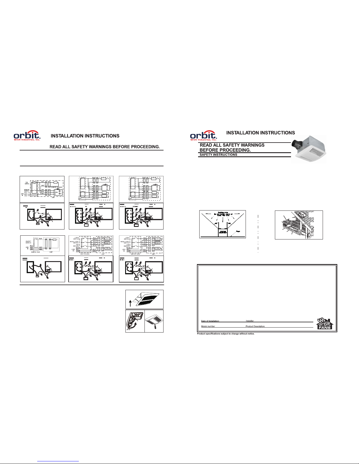
Wire panel
Model OD80H OD110H ODU814H
Model OD80LH OD80LLH OD110LH OD110LLH ODU814LH ODU814LLH
ODU814H
FAN
WIRE
PANEL
UNIT
BLACK (BLK)
SWITCH BOX
FAN
POWER SUPPLY
120V AC
GROUND (GRD)
WHITE(WHT)
FAN
CONNECTOR
UNIT
BLACK (BLK)
NIGHT
LIGHT
LIGHT
SWITCH BOX
FAN
120V AC LINE IN
GROUND (GRD)
RED
WHITE (WHT)
BLUE (BLU)
FAN
CONNECTOR
LIGHT
CONNECTOR
WIRE
PANEL
ODU814LH
OD80H
OD110H
WIRE
PANEL
UNIT
BLACK(BLK)
SENSOR
SWITCH BOX
FAN
POWER SUPPLY
120V AC
GROUND (GRD)
BROWN(BRN)
WHITE(WHT)
FAN
CONNECTOR
FAN
SWITCH BOX
HUMIDITY
HUMIDITY
HUMIDITY
SENSOR
CONNECTOR
OD80LH
OD110LH
UNIT
SENSOR
LIGHT
NIGHT
LIGHT
SWITCH BOX
FAN
120V AC LINE IN
GROUND (GRD)
BROWN (BRN)
FAN
CONNECTOR
SENSOR
CONNECTOR
LIGHT
CONNECTOR
RED
BLACK (BLK)
WHITE (WHT)
BLUE (BLU)
Humidity Sensor
UNIT
Motor
N
GRD
GRD
SWITCH BOX
BLK
BLK
WHT
BLK
WHT
FAN
SWITCH
SENSOR
SWITCH
LINE
IN
C
O
M
L
WHT
TT
HH
LIGHT
SWITCH
WHT
WHT
NIGHT LIGHT
SWITCH
BLU
RED
LIGHT
NIGHT
LIGHT
BRN
FAN
WIRE
PANEL
WIR ING DIA GRAMS :
Deluxe
“ODH” Series
WIR ING: Po wer mus t be disc onnec ted dur ing ins talla tion.
1. Run e lectr ical as d irect ly as pos sible f rom the w all swi tch to th e unit.
2. Usi ng appr oved co nnect ors, co nnect c ables w ires ac cordi ng to the m odel a nd diag ram bel ow to the j uncti on box.
3. Do no t allow c able to t ouch si de of uni t after i nstal latio n.
4
OD80LLH
OD110LLH
UNIT
SENSOR
LIGHT
NIGHT
LIGHT
SWITCH BOX
FAN
120V AC LINE IN
GROUND (GRD)
BROWN (BRN)
FAN
CONNECTOR
SENSOR
CONNECTOR
LIGHT
CONNECTOR
RED
BLACK (BLK)
WHITE (WHT)
BLUE (BLU)
Humidity Sensor
UNIT
Motor
N
GRD
GRD
SWITCH BOX
BLK
BLK
WHT
BLK
WHT
FAN
SWITCH
SENSOR
SWITCH
LINE
IN
C
O
M
L
WHT
TT
HH
LIGHT
SWITCH
WHT
WHT
NIGHT LIGHT
SWITCH
BLU
RED
LIGHT
NIGHT
LIGHT
BRN
FAN
WIRE
PANEL
UNIT
BLACK (BLK)
NIGHT
LIGHT
LIGHT
SWITCH BOX
FAN
120V AC LINE IN
GROUND (GRD)
RED
WHITE (WHT)
BLUE (BLU)
FAN
CONNECTOR
LIGHT
CONNECTOR
WIRE
PANEL
ODU814LLH
VER 2
Deluxe
“ODH” Series
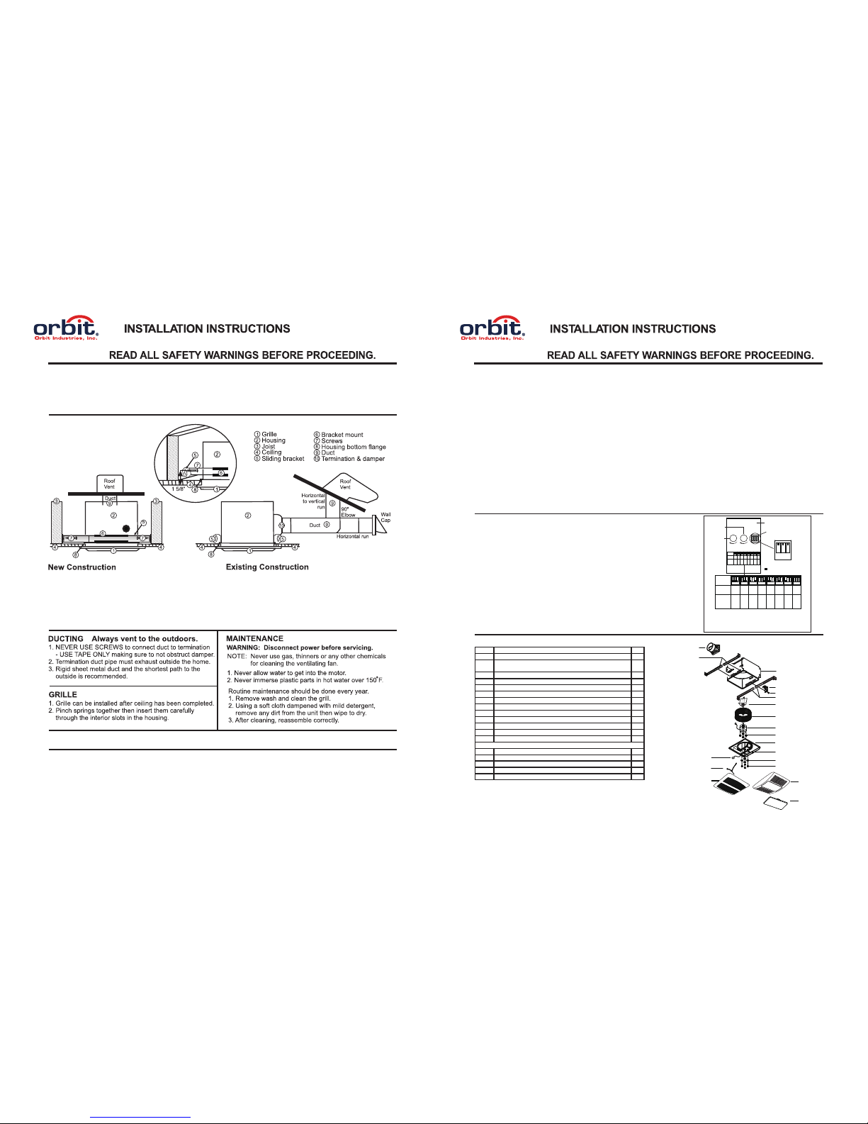
4” & 6” Ter minat ion (du ct)
Rou gh Open ing:
11-1 /4” L X 10-1 /2” W
Hou sing Di mensi on:
11-1 /4” L X 10-1 /2” W X 7-5 /8” H
Car efull y posit ion fan
for s horte st duct r un and
few est elb ows to ac hieve
max imum pe rform ance
1. Re move gr ille fr om hous ing bef ore ins talla tion.
2. In sert pa ir of sli ding br acket s in each b racke t mount .
3. Lo cate ho using b etwee n ceili ng jois ts and tr uss so bo ttom
fla nge wil l fit flu sh to the c eilin g joist .
4. Lo osely s crew to j oist th rough t he moun ting br acket
KEY HOLE sl ots (scr ews not p rovid ed).
5. Op tiona l side mo unt to ce iling j oist an d use one s ide of th e
bra cket for m ore sta ble su pport .
1. Fo r new fan i nstal latio n posit ion the h ousin g in the
att ic next to t he ceil ing jo ist or tru ss.
2. Tra ce hous ing bot tom edg e on ceil ing mat erial f or cuto ut.
3. Co nfirm t he open ing, th en cut ho le 11-1/4 ” X 10-1/ 2” of the
hou sing in side ed ge.
4. Pl ace hou sing in side op ening ( attic ) of the ce iling .
5. To atta ch foll ow step s 3, 4, 5 for N ew Cons truct ion.
HUMIDITY SENSOR OPERATION
The humidity sensing fan uses a sophisticated humidity sensor that responds to: (a) rapid to moderate (user adjustable)
increases in humidity or (b) humidity above a user adjustable set point (50%-100% relative humidity). The humidity sensor
may occasionally turn the fan ON when environmental conditions change. If the fan continuously responds to changing
environmental conditions, adjustment “H” (humidity) may be required. The fan is factory set for about 75% (ambient
temperature of 77 F).
OPERATION
o
2
Deluxe
“ODH” Series
SENSITIVITY ADJUSTMENT
The “H” has been factory set for most shower applications. However, if the fan is in a tub area or is being used for dampness
H “+” may need to adjust to maximum setting. If the control is responding too often to changing environmental conditions,
adjust H “-” to lower the setting.
To adjust the “H”:
1. Disconnect power at service entrance.
2. Through the grille, locate the slot marked “H”.
3. Carefully rotate the “H” adjustment toward “+” or “-”.
4. Turn on power and check operation by turning on the shower or other humidity source until the fan turns ON.
5. Repeat above steps if necessary.
Humidity sensor has a deviation values when the temperature changes.
TIMER ADJUSTMENT (For model OD80H OD110H OD80LH OD110LH OD80LLH and OD110LLH )
The humidity sensing fan has a timer “T” that can be adjusted from 5 to 60 minutes (factory setting is 20 minutes). This “T”
controls the length of time that the fan remains ON after the sensor has stopped sensing a rise in humidity and the humidity
level is below the user adjusted set point.
To adjust Timer “T”:
1. Disconnect power at service entrance;
2. Through the grille, locate the slot marked “T”;
3. Carefully rotate the “T” and adjust to desired setting (from 5 to 60 minutes).
4. Check by turning ON the Humidity switch until the fan turn ON.
5. Turn the Humidity Switch OFF and time the unit.
The control box, located inside the fan housing, has three separate adjustments:
(1) The Low Airflow Knob adjusts the airflow from 30CFM up to the air flow rate of
the high fan speed determined by the dip switch setting.
(2) The Humidity Sensor Knob set user adjustable setpoint.
(3) The Dip Switch will adjust the fan speed setting from 80 to 120 CFM using a
4" duct or 90 to 140 CFM using a 6" duct.
Note: Both 4" & 6" duct adaptors are included.
Fan run continuously at a low speed(adjustable by low airflow knob) and automatically
boost up to high speed when humidity above a user adjustable setpoint
(50%-100% relative humidity).
After delay timer (20 minutes) returns fan to the default low speed.
Model ODU814H ODU814LH ODU814LLH
-
+
-
+
1 2 3
1
Dip Switch
Power box
Low Airflow
Knob
Humidity
Sensor Knob
80 90 110 120 90 110 120 140
1
6"
Switch
position
Duct
diameter
(inches)
Airflow
(CFM)
6"
6"
6"4"4"4"4"
80 90 110120 90 110 120 140
12312312 312
3123123
123123
6"
Switch
position
Duct
diameter
(inches)
Air deliver
(CFM)
6"
6"
6"4"4"4"4"
Other airflow reference performance based on HVI Procedures
915, 916, and 920.
Factory setting: 110CFM ( )
HVI Certified performance based on HVI Procedures 915, 916,
and 920.
with 6" duct
2 3
2 3
1 2 3
1 2 3
1 2 3 1 2 3 1 23 1 2 3 1 2 3
Dip Switch Position
* Blower Assembly includes part 6, 5, d, 4, c, b, a.
Replacement installation:
Remove the screw (part c), then take out the motor plate (part 4) from the housing (part 9) by pushing
down the rib in the plate while pulling out on the side of the housing. Replace the broken parts.
5
6
d
e
a
1a
2
3
4
b
c
1b
12
7
9
8
10
10
11
PART PART NAME Qty.
1b
2
3
4
5
6
7
8
9
10
11
12
a
b
c
d
e
Housing
Damper / Duct Connector
Lens
Wiring plate
Screw
Blower Wheel
Wire Panel / Harness Assembly
Motor
1
2
1
1
1
1
1
1
1
4
1
1
4
4
1
4
1
Isolator
Motor Plate
Washer
Nut, Hex Lock
Grille Assembly (includes part 2)
1a
Grille Spring
Bar Hanger Kit
Screw
Power box
Model OD80H OD110H ODU814H
Model OD80LH OD80LLH OD110LH
OD110LLH ODU814LH ODU814LLH
SERVICE PARTS
WARNING: Power must be disconnected before servicing.
Grille Assembly (includes part 2)
1
3
 Loading...