

Page 1

OPTIMOD-FM 2200 INSTALLATION
Section 2
Installation
page contents
2-2 Installation of 2200
2-7 Figure 2-1: AC Line Cord Wire Standard
2-9 Figure 2-2: Wiring the 25-pin Remote Control Connector
2-1
2-17
2-27 System Setup Controls
2-27 I/O CALIB (I/O Calibrat ion )
2-32 Stereo Encoder (and processing Pre-Emphasis)
2-34 Remote Interface
2-35 TEST Mode
Basic System Setup
CAUTION
The installation and servicing instructions in this manual are for
use by qualified personnel only. To avoid electric shock, do not
perform any servicing other than that contained in the Operating
Instructions unless you are qualified to do so. Refer all servicing
to qualified service personnel.
pagecontents
Page 2

2-2
INSTALLATION OPTIMOD-FM 2200
Installation of 2200
Allow about 2 hours for installation.
Installation co nsists of: (1) unpacking and insp ecting the 2200, (2) optional rese tting of
jumpers for 2200 op tions (compos ite output impedance , input termination, inp ut sensitivity), (3) checking the line voltage setting, fuses and power cord, (4) mounting the 2200 in a
rack, (5) connecting inputs, outputs and power, (6) setting the
optional connecting of remote control leads.
When you have finished installing the 2200, proceed to “System Setup,” on page 2-16.
1. Unpack and inspect.
A If you note obvious phys ical damage, contact the carrier immediate ly to make a
damage claim. Packed with the 2200 are:
1 Operating Manual
1 Quick Setup Guide
1Line Cord
2
1
⁄2A Replacement Fuses for “U” and “J” V ersions
2 250mA Replacement Fuses for “E” Version
1 Orban green screwdriver (Xcelite R3323)
1 Booklet: Audio Quality in the FM Plant
GROUND LIFT switch, (7 ) and
B Save all packing materials! If you should ever have to ship the 2200 (e.g., for
servicing), it is best to ship it in the original carton with its packing materials because
both the carton and packing material have been carefully designed to protect the unit.
C Complete the Regi str ati on Car d and return it to Or ban. (please)
The Registration Card enables us to inform you of new applications,
performance improve ments, and service aids tha t may be develo ped, and it
helps us respond promptly to cla ims unde r warr anty with out our hav ing to
request a copy of your bill of sale or other proof of purchase . Please f ill in
the Registration Card and send it to us today. (The Registration Card is
located aft er the cover page).
We do not sell or give away our customer’s names to anyone.
Page 3

OPTIMOD-FM 2200 INSTALLATION
2. Change standard factor y configuration, if required.
[Skip this step if your installation does not have any special requirements.]
The 2200 is s upplied from the f ac tory with its jumpe rs set to th e con figur ation c orre ct
for most installations.
Stereo Encoder Composite Output Impedance 0Ω
Input Impedance 10kΩ
Input Sensitivity −10dBu or greater (+5dBu to +27dBu peak)
A To change any jumpers you must remove the top cover of the 2200 to access the main
circuit board. (Make sure p ower is not con nected. ) Remove all scr ews ho lding the
cover in place, then lift it off. (B e careful not to strip thre ads when opening the
cover.)
B Refer to Figure 2-1 to find the jumpers on the main circuit board and to position them
according to your application.
The following inf ormation is provided to explain each jumper and its settings in detail.
2-3
Stereo encoder composite output impedance.
•
[Do not change the default 0Ω jumper setting unless your installation
needs 75Ω source impedance.]
The stereo encoder is shipp ed from the facto ry with 0Ω source imp edan ce.
This is correct for virtually all installations. However, the 2200 stereo
encoder can be changed to 75Ω source impedance if desired.
The frequencies in the stereo baseband are low by comparison to RF or
video, and the ch aracteristic imped ance of coaxial cab le is not 75Ω at lower
frequencies, so the transmission system will ha ve more accu rate amplitud e
and phase response (and thus, better stereo separ ation) if the cab le is driven
by a very low source impedance (0Ω) and is terminated with greater than
1kΩ at the exciter.
However, a few broadcast organizations require that FM composite be
transmitted in impedan ce-matche d coaxial ca ble with 75Ω sourc e and load
impedances.
To change the source impedance of one or both of the composite
outputs:
To change the sou rc e imp ed ance of comp osite ou tpu t #1, move jum per JA
to the “75Ω” position (Fig 2-1). To change the source impedance of
composite output #2, move jumpe r JB to the “7 5Ω” po sition (Fig 2-1).
Analog left/right input termination.
•
[Do not change the default setting unless your installation requires 600Ω
termination on the analog left/right inputs.]
The analog left/right inputs are shipped from the factory with balanced
bridging (1 0kΩ) input impe dance. Howev er, the 2200 a nalog inputs ca n be
changed to 600Ω input impedance.
Page 4

2-4
INSTALLATION OPTIMOD-FM 2200
To change the input impedance of the analog left /rig ht inputs:
Move jumpers J301 and J305 according to Figure 2-1. Jumper J301 sets
the left channel and jumper J305 sets the right channel .
Set analog left/right input sensitivity.
•
[Skip this step if your installation will supply the 22 00 with nominal input
level of −10dBu or greater (+5dBu to +27 dBu peak).]
The analog left/right inputs are shipped from the factory with input sensitivity to accommodate inputs whose absolute maximum peak level is
between +5dBu and +27dBu.
If VU meters are used, +5dBu to +27dBu absolute peak corresponds to a
0VU level of approximate ly −9dBu to +13dBu.
If PPMs are used, +5dBu to +27dBu absolute peak corresponds to a PPM
level of approximate ly −2dBu to +20dBu.
However, in unusual circumstances where the input level is very low, the
2200 analog inputs can be changed for greater sensitivity. This usually
occurs only when the stu dio-to-transmitter link i s a long telephone or po st
line with a passive equalize r at the re ceive end a nd no amplifier to make u p
the loss of the line and the equalizer .
To increase the input sensitivity of the analog input to accommodate
absolute peak levels of −17dBu to +5dBu (nominal levels down to
−30dBu):
Move jumpers J302, J303, J306, J307 and J308 according to Figure 2-1.
Jumpers J30 2 and J303 set the lef t channel and jumpers J306 and J307 set
the right channel. Jumper J308 sets the co ntrol cir cuit to r ecogniz e the n ew
input sensitivity.
C Replace the 2200 top cover.
Replace all screws snugly. (Be ca re ful not to strip thr ea ds by fa stenin g the
screws too tightly.)
Page 5

OPTIMOD-FM 2200 INSTALLATION
2-5
Page 6

2-6
INSTALLATION OPTIMOD-FM 2200
2200 Rear Panel
Voltage Selector (for Model Numbers 2200/U, 2200-D/U, 2200/E and 2200-D/E) can
be set to 115V (for 100-132V operation) or 230V (for 200-264V operation); (for
Model 2200/J and 2200-D/J) set to 115V (for 89-120V operation).
Fuse values can be changed to support 115V or 230V operation. Fuse must be 3AG
Slow-Blow,
Power Cord is detachabl e and is termina ted in a “U- ground ” plug (USA st andard), or
CEE7/7 plug (Continental Europe), as appropriate to your 2200’s Model Number.
GND LIFT (Ground Lift) Switch can be set to
ground to its chassis) , or to
driving its composite output into an unbalanced exciter input).
Remote Cont rol In terf ace is pr ov ided to conn ect the 2200 to a re mote contr ol. Th e
2200 remote control accepts a DB-25 connector and supports user-programmable
selection of up to eight inputs fo r any one of the fo llowing para meters: u ser presets ,
factory presets, bypass, tone, exit test, stereo, mono left, mono right, mono sum, analog
input, digital inp ut (Model 2200-D only), digital input + J.17 pre-emphas is (Model
2200-D only).
COMPOSITE 1 OUTPUT and COMPO SITE 2 OUTPUT are provided, each with
independent output level control (via front panel Comp 1 and Comp 2 controls). Each
output uses a BNC connector.
1
⁄2-amp for 115V, or 1⁄4-amp (250mA) “T ” type for 230V.
GND ( to connect the 2 200’s circuit
LIFT (if you a re using the 2200 ’s ster eo enc oder, an d are
A valid signal is a momentary tr ansition from no-c urrent to cu rrent flowing
through the particular remote signal pins. Current must flow for at least
50ms for the signal to be interpreted as valid. It is acceptable to apply
current continuously to an input, DC or AC. Do not exceed 9 volts unless
you use an external current-limiting resistor that limits curr ent to 10mA.
ANALOG INPUT and ANALOG OUTPUT provided to support left and right audio
signals through XLR-type connectors.
Digital AES/EBU INPUT and AES/EBU OUTPUT (Model 2200-D only) are
provided to support two-channel AES/EBU-standard digital audio signals through
XLR-type connectors.
Page 7
OPTIMOD-FM 2200 INSTALLATION
3. Check the line voltage, fuse and power cord.
A DO NOT connect power to the unit yet!
B Check the voltage selector. This is on the rear panel.
Refer to the unit’s re ar panel fo r your Model Numb er and the in side o f th e
front cover of this manual for your Model Number’s line volta ge settin g.
Model Numbers 2200/U, 2200-D/U, 2200/E and 2200-D/E are shipped
configured for either 100-132V or 200-264V, 50Hz or 60Hz operation, as
indicated on the rear pane l. To change the opera ting voltage, set the voltag e
selector to 115V (for 100-132V) or 230V (f or 200 -264 V) as appro pr iate .
Model Number 2200/J and 2200-D/J are shipped for 89-120V, 50/60Hz
operation. The voltage selecto r shou ld be set to 115V (f or 89-12 0V) .
C Check the value of the fuse and change the fuse if the value is incorrect.
For safety, the fuse must be Slow-Blow 1⁄2-amp for 115V, or 250mA
1
(
⁄4-amp) “T” type fo r 23 0V.
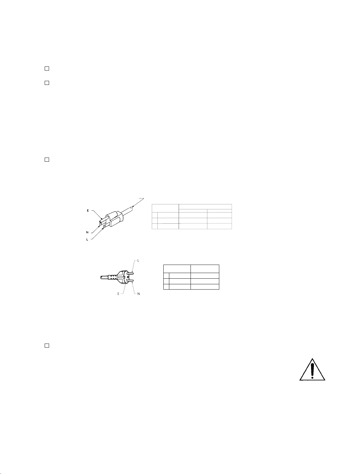
TYPE 18/3 SVT COR, TYP
(3 x .82 mm2)
WIRE COLOR
NORMAL ALT
BROWN
BLUE
GREEN-YELLOW
BLACK
WHITE
GREEN
PLUG FOR
115 VAC
(USA)
CONDUCTOR
L
LINE
NEUTRAL
N
E
EARTH GND
2-7
TYPE H05VV - F - 0.75
PLUG FOR
(EUROPEAN)
Figure 2-1: AC Line Cord Wire Standar d
D Check po wer cor d.
AC power passes through an IEC-standard mains connector and an RF
filter designed to meet the standa rd s of all inter na tion al sa fe ty au tho ritie s.
The power cord is terminated in a “U-ground” plug (USA standard), or
CEE7/7 plug (Continental Europe), as appropriate to your 2200’s Model
Number. The green/yellow wire is connected directly to the 2200 chassis.
If you need to change the plug to meet your country’s standard and you are
qualified to do so, see Figure 2-2. Otherwise, purchase a new mains cord
with the correct line plug attache d.
230 VAC
CONDUCTOR WIRE COLOR
L
NEUTRAL
N
E
EARTH GND
LINE
BROWN
BLUE
GREEN-YELLOW
Page 8

2-8
INSTALLATION OPTIMOD-FM 2200
4. Set Ground Lift switch.
GND LIFT switch is located on the rear panel.
The
GND LIFT switch is shipped fr om the fac tory set to ground (to co nnect the 2200’s
The
circuit ground to its chassis ground). If you are using the 2200’s stereo encoder, and are
driving its composite outp ut into an unbalanced exciter input, set the
to
LIFT.
GND LIFT switch
This will break a ground loop that could otherwise occur.
Unbalanced exciter inputs can cause hum and noise because it is difficult to control the
system ground ing. If hum or n oise appears that cannot be c ured by rese tting the
LIFT
switch, we suggest that y ou ins tall the optional Orban CIT25 Composite Iso lation
Transformer at the exciter’s input to balance it. If you use the CIT25, set the 2200’s
LIFT
switch to GND.
GND
GND
If you are not using the 2200’s stereo encoder, set the GND LIFT switch to ground.
5. Mount the 2200 in a r ack.
The 2200 requires one standard rack unit (1
3
⁄4 inches/4.4 cm).
There shou ld be a good gr ound connec tion betwee n the rack a nd the 2200 ch assis —
check this with an ohmmeter to verify that the resistance is less than 0.5Ω.
Mounting the unit o ver large heat-producing devic es (such as a vacuum- tube power
amplifier) may sh or ten c omp on en t lif e an d is no t recommended. Ambie nt temperature
should not exceed 113°F/45°C when equipment is powered.
Equipment life will be exten de d if the unit is mou nte d away from sou rc es of vibration,
such as large blowers.
The shorter the baseband cable run from the 2200 to exciter, the less like ly that ground
loops or other nois e problems will occur in the insta llation. If you require a lo ng c ab le
run, it is usually best to mount the RF exciter close to the 2200 , and to make the long
cable carry the RF output from the exciter to the transmitter’s RF power amplifiers.
Page 9
OPTIMOD-FM 2200 INSTALLATION
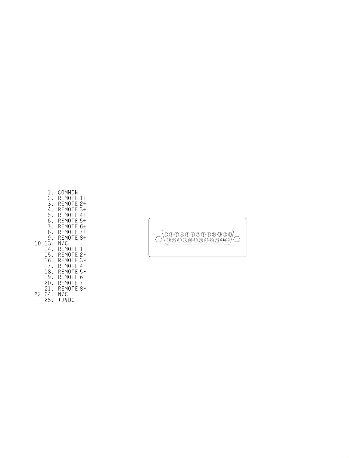
6. Connect remote control. (optional)
The 2200 has extensive remote control provisions, which are described on page 2-34.
Optically-isolated remote control connections are terminated in a type DB-25 male
connector located on the rear panel. It is wired according to Fig. 2-2. T o select the desired
function, apply a 5-12V A C or DC pulse be tween the a ppropriate
The (−) terminals can be conne cted togethe r and then c onnected to gr ound at pin 1 to
create a
composition resistor in series with the
current limiting. A current-limited +9VDC source is available on pin 25.
REMOTE COMMON. If you use 48V, connect a 3.6K 10%, 1-watt carbon
REMOTE COMMON or the (+) terminal to provide
In a high-RF environment, these wires should be short and should be run
through foil-shielded cable, with the shield connected to the connector
shell at both ends.
PIN ASSIGNMENT
REMOTE terminals.
2-9
REMOTE INTERFACE
Figure 2-2: Wiring the 25-pin Remote Control Connector
7. Connect inputs and outputs.
See the hook-up and grounding information on the following pages.
Audio Input and Audio Output Connections Page 2-10
Composite Output Page 2-12
AES/EBU Digital Input and Output (2200-D only) Page 2-11
Grounding Page 2-12
Page 10

2-10
INSTALLATION OPTIMOD-FM 2200
Audio Input and Output Connections
Cable
We recommend usin g two-conductor foil-shielded cable (such as Belden 8451 or
equivalent), because signal current flows through the two conductors only. The shield
does not carry signal, and is used only for shielding.
Connectors
Input and output connectors are XLR-type connectors.
•
In the XLR-type c onne ctors, pin 1 is CHASSIS GROUND, while pin 2 and
pin 3 are a balanced, floating pair. This wiring scheme is compatible with
any studio wiring standard: If one pin is considered
automatically
HIGH.
Analog Audio Input
LOW, the other pin is
Nominal input level between −30dBu and +8dBu will result in normal oper ation
•
of the 2200. (See step 2 on page 2-3 for a full discussion).
(0dBu = 0.775Vrms. For this application, the dBm @600Ω scale on
voltmeters can be read as if it were ca libr ate d in dBu. )
The peak input level that causes overload is dependent on the setting of the AI
•
CLIP control. It is adjustable from −17dBu to +27dBu in two ranges.
The electronically -bal anced i nput uses an ultra low noise and distortion differ-
•
ential amplifier for best common mode rejection, and is co mpatible with most
professional and semi-professional audio equipment, balanced or unbalanced,
having a source impedance of 600Ω or less. The input is EMI suppressed.
Input connec tion s a re th e sa me w he the r the d riv ing sou rc e is balanced or unbal-
•
anced.
Connect the red (or white) wire to the pin on the XLR-type connec tor (#2 or #3)
•
that is considered
wire to the pin on the XLR - typ e c on ne cto r (# 3 or #2) th at is considered
the standards of your organization. (Note: International Standard is pin 2
*In low RF fields (like a studio site), do not connect the cable shield at the 2200
•
input — it should be con ne cte d at the sou rc e en d on ly. In h igh RF fields (like a
transmitter site), also connect the shield to pin 1 of the male XLR-type connector
at the 2200 input.
HIGH by the standards of your organization. Connect the black
LOW by
HIGH .)
If the output of the driving unit is unbalanced and does not have separate CHASSIS
•
GROUND and (−) (or LO) output terminals, con nect both the shield an d the black
wire to the common (−) or ground terminal of the driving unit.
Page 11

OPTIMOD-FM 2200 INSTALLATION
Analog Audio Output
Electronically-balanced and floating outputs simulate a true transfo rme r out-
•
put. The source impedance is 30Ω. The output is capable of driving loads of 600Ω
or higher; maximum output level is +20dBu. The outpu t s ar e EM I su pp re ss ed .
If an unbalanced output is required (to drive unbalanced inputs of other equip-
•
ment), it should be taken between pin 2 and pin 3 of the XLR-type connector.
Connect the
organization ’s standards) to circu it ground, and take the
remaining pin. No special pr ecaution s are re quired eve n though one side of the
output is grounded.
Use two-conductor foil-shielded cable (Belden 8451, or equivalent).
•
At the 2200’s output (and at the output of other equipment in the system), connect
•
the cable’s shie ld to the
connector. Connect the red (or white) wire to the pin on the XLR-type connector
(#2 or #3) th at is co nside red
the black wire to the p in on the XLR-type conn ector (#3 o r #2) tha t is c onsidered
LOW by the standards of your organization.
LOW pin of the XLR-type c onnector ( #3 or #2 , depending o n your
HIGH output from th e
CHASSIS GROUND terminal (pin 1) on the XLR- type
HIGH by the standards of your organization. Connect
2-11
AES/EBU Digital Input and Output (2200-D Only)
Model 2200-D includes an AES/EBU digital input/output connector. These follow the
AES/EBU standa rd.
Use 110Ω shielded twisted-pair cable (Belden 1800A, or equivalent). The length
•
of cable, cable characteristics, and quality of termination become extremely
important because AES/EBU signals have a spectrum with significant energy to
6MHz. Do not use standard au di o cab le fo r AES/E BU a pplica tion s.
Impedance mismatch ing and noise are the most common causes of trouble
with AES/EBU signals, usually manifestin g as pops or clicks in the o utput
audio, or total loss of synchronization lock. Impedance mismatching can
be caused by use of an inappropriate cable type, poor cable termination
technique, or improper termination of the transmission line either in the
source, or receiver equipment. Induced noise may prevent the AES/EBU
receiver from locking to the incoming data stream. For this reason, cable
length is generally rec ommended to be less tha n 100 meters (a pprox. 328’).
Each digital input or output line carries both the left and right stereo
channels. The digital input clip level is fixed at 0dB relative to the maximum digital word (0dBFS). Sin ce the inp ut meter s mo nitor clip le vel s, th e
maximum digital input will make the meters display 0dB. The reference
level is adjustable using either the
reference level determines the amount of gain reduction. The output level
is adjustable using the
to full scale, and is adjustable from 0.0dBFS to −20dBFS.
DO 100% control. This control is in dB, referenced
DI REF VU or DI REF PPM contro ls. The
Page 12

2-12
INSTALLATION OPTIMOD-FM 2200
Composite Output
There are two independent composite baseband outputs (containing the encoded
•
stereo signal and the stereo pilot tone).
Each output has an independent output level control and can be strapped
for 0Ω or 75Ω source im pe danc e. Ea ch outpu t ca n d rive u p to 8V peak -to peak into 75Ω in para llel with up to 0.047
before any noticeable performance degradation occurs.
Connect the 2200’s c omposite output to the exciter input with up to 100 feet
•
(30.5m) of RG-58/U or RG-59 /U coaxial cable termina ted with BNC connectors.
Longer runs of coax may increase problems with noise, hum, and RF
pickup at the exciter. In general, the least troublesome installations place
the 2200 close to the excite r a nd limit th e le ng th o f th e c om posite ca ble to
less than 6 feet (1.8m).
We do not recommend that the excite r inpu t be ter minate d by 50Ω or 75Ω
unless this is unavoidable. Because the frequencies in the stereo baseband
are low by comparison to RF or video, and because the characteristic
impedance of coaxial cable is not constant at very low frequencies, the
transmission system tends to have more accurate amplitude and phase
response (and thus, better stere o sepa ration ) if the coax is driv en by a ver y
low impedance source and is terminated with greater than 1kΩ at the
exciter end. This also eases thermal stresses on the output amplifier in the
stereo encoder, and can thus increas e equipme nt life.
If the Orban CIT25 Composite Isolation Transformer is used, the exciter
must present a 1kΩ or greater load to the transformer for proper trans-
former operation.
Designed to be installed adjacent to each exciter, the CIT25 Composite
Isolation Transformer provides ground loop isolation between the OPTIMOD-FM composite output and the exciter’s input, and presents OPTIMOD-FM with a balanced floating loa d.
µF in cable and input capacita nce
Grounding
Very often, g rounding is approach ed in a “hit or miss” manner. But with ca re it is
possible to wire an au dio studio so that it provides maximum protec tion from powe r
faults and is free from ground loops (which induce hum and can cause oscillation).
In an ideal system:
All units in the system should have balanced inputs. In a modern system with low
•
output impedances and high input impedances, a balanced input will provide
common-mode rejection and prevent ground loops — regardless of whether it is
driven from a balanced or unbalanced source.
The 2200 ha s b a lanced in puts.
Page 13

OPTIMOD-FM 2200 INSTALLATION
(Grounding continued)
All equipment circuit grounds must be connected to ea ch other; all equipment
•
chassis grounds must be connected together.
In a low RF field, aud io cable shields should be connected at one end only —
•
preferably the source (output) end.
In a high RF field, audio cable shields should be connected to a solid earth ground
•
at both ends to achieve best shielding against RFI.
Whenever coaxial cable is used, shields are automatically grounded at both ends
•
through the terminating BNC connectors.
Power Ground
Ground the 2200 chassis through the third wire in the power cord. Proper
•
grounding t echniqu es never leave equipment chassis unconnected to power/earth
ground. A proper power ground is essential to safe operation. Lifting a chassis
from power ground creates a po tential safety hazard.
2-13
Circuit Ground
To maintain the same potential in all equipme nt, the circu it (audio) grou nds mus t be
connected togeth er:
Circuit and chassis ground should always be connected by setting the 2200’s GND
•
LIFT switch to GND, except w hen the 2200 ’s optional s tereo encode r composite
output is driving an unbalanced exciter input. This is an unbalanced-to-unbalanced connection, so the ground loop that would otherwise occur must be broken
by setting the 2200’s
Alternately, you can balance and float the exciter input with the Orban
CIT25 Composite Isolation Transformer — (call Orban Customer Service).
In high RF fields, th e s ystem is usually gro unde d th ro ug h th e e qu ipme nt r ac k in
•
which the 2200 is mounted. The rack should be connected to a solid earth ground
by a wide copper strap — wire is completely ineffective at VHF because of the
wire’s self-inductance .
GROUND LIFT switch to LIFT.
Older Exciters
Most exciters have straightforward wideband inputs, and no special considerations are involved. If you have an older exciter requiring special wideband interfaces,
contact Orban Customer Service.
Page 14

2-14
INSTALLATION OPTIMOD-FM 2200
8. Power up the 2200.
A Plug in the 2200’s power cord.
With no i np ut pr og ra m mat eri al, the re d Gat ed LE D and o ne of t he green
Function LEDs should be on. The AGC meter should ind ica te 10.0 .
The main screen app ears in the front window display .
on air:CLASSICAL PROTECT
AnlgIn_Stereo
The main or “home” screen shows which processing preset is selected to
be on-air, th e type of in put (analo g or digital), and the stereo enco der mode.
If the main screen does not a ppear, repeated ly press the Escape butto n until
it does appear.
9. Physical install at i on i s com plete.
A Continue with system software configuration, on page 2-16.
We recommend you browse through the explanation of 2200 front panel
controls and mete rs (on the f ollowing page s) befo re y ou bein g conf igurin g
system software.
Page 15

OPTIMOD-FM 2200 INSTALLATION
2200 Front Panel
Screen Display labels the four soft key buttons and provides control setting information.
Screen Saver feature: The screen has a built-in screen saver that turns off
the backlight afte r appro ximately one hour. The screen turns back on when
any front panel control is touched. Note that buttons don’t perform their
normal function when the screen is blank. Similarly, the control knob’s
first turn is not read, until it stops for a second or so.
Contrast Button adjusts the optimum viewing angle of the screen display. Press this
button to cycle through four contrast settings for the screen display.
Four Soft Key Buttons provide access to all 2200 functions and controls. The
functions of the buttons change with each screen according to the labels at the bottom
of each screen. Push a button:
To select options (always identified on the screen by all-capital-letter
words surrounded by left and right vertical bars), press the button directly
below the option.
To change a para meter setting (always identified by lower-case letter s or
numerals), hold down the button directly be low the param eter setting, turn
the control knob to scro ll throu gh ch oic es, and re lea se the button to set th e
parameter.
2-15
Control Knob is used for changing data in one of three methods.
To scroll through submenu choices: Presets (on Recall Preset screen),
FULL CONTROL parameters (on Modify Processing FULL CONTROL
screen) and 8 Remote Inter fa ces (on System Setu p REMOTE INT ERFACE
screen).
To change a para meter setting, by sim ultaneously holding down a soft key .
The parameters being changed take effect immediately, except for the
following system level contro ls:
Encoder sc reen),
XTLK TEST. The setting for these controls do not take effect until th e soft
key is released.
To adjust the
sound immediately.
INPUT, AO PRE-E, DO PRE-E, DO RATE, DO SYNC and
LESS-MORE control. Adjusting this control changes the
MODE (on test sc re en ), MODE ( on Stereo
Escape Button returns the user to the previous screen; pressing this button repeatedly
will always return you to main screen, which shows the on-air preset name.
Recall Preset Button brings up a screen that displays the current on-air preset and next
preset (w hich ca n be c hanged by tur ning the contro l knob). To pu t a differ ent pr eset
on-air, turn the control knob to fin d the preset desir ed, then pres s the
RECALL NEXT
soft key.
When the button’s yellow LED is lit, the Recall Pre set scre en is display ed.
Page 16

2-16
INSTALLATION OPTIMOD-FM 2200
Modify Proces sing Butt on brings up a screen to modify par ameters for the current
on-air pres et. For Two-Band pr esets:
Protection preset,
When the button’s yellow LED is lit, th e Modify Proc essing screen (or one
of its submenus) is displayed.
DRIVE and 30HzHPF.
LESS-MORE, EQ and FULL CONTROL. For the
System Setup Button brings up a screen to modify system settings (such as I/O
levels). There are four System S etup submenus:
MOTE INTERFACE
When the button’s yellow LED is lit, the System Setup screen (or one of
its submenus) is displayed.
, TEST.
I/O CALIB, STEREO ENCODER, RE-
Gain Reduction Meters indicate AGC, Bass, and Master Gain Reduction. All three
meters operate over a −25.0dB to 2.5dB range. Note that the AGC and Bass meters are
off when the Prot ect preset i s on-air.
HF Limiting LEDs light when the high-freque nc y con ten t of au dio is b eing limite d
by the very fast high-frequency limiters. These LEDs indicate when greater than 0.5dB
HF limiting is occurring.
Gated LED indicates gate activity, lighting when the input audio falls below the
threshold se t by the gate threshold control (Mo dify Processing screen
GATE THRS
control). When th is happe ns, th e comp ress or’s re cove ry time is dras tica lly slowed to
prevent noise rush-up during low-level passages.
Composite Meter is a 10-segment bargraph showing the stereo encoder’s composite
output level before the composite level controls.
Function Button selects which of three functions are displayed in the Function
meters: Enhance, L/R Input or L/R Output.
Function LEDs indicate which function is currently displayed by the Function meters:
Enhance, L/R In put or L/R O utput. Press the Function button to tog gle between th e
three functions.
Function Meter indicates level of Enhance, L/R Channel Input or Output, as selected
with Function button. The meters operate over a −27dB to 0dB range. Input meters are
referenced to clip leve l. Output mete rs are ref erence d to 100% modulation leve l. HF
Enhance meter shows the active amount of enhancement activity. Since the HF
Enhancement is program-dependent, it will vary with source material and the HF
parameter. Note: HF Enhance is displayed only on the left-ha nd meter, be low “HF. ”
Stereo Encoder Screwdriver-Adjustable Controls
Orban supplies a special green-handled flat-blade screwdriver (Xcelite
R3323) to adjust the stereo encoder controls.
Comp 1 sets the output level of Composite Output 1.
Comp 2 sets the output level of Composite Output 2.
Page 17

OPTIMOD-FM 2200 INSTALLATION
Basic System Setup
Allow about about 30 minutes for system setup.
You can set up all of the 2200’s required settings through Basic System Setup. It is a guided
procedure for adjusting all of the setup adjustments n eeded to get y ou on the air. System
setup consists of: (1 ) setting the pre- emphasis, (2) se tting the analog input pe ak level, (3)
setting the input reference level, (4) adjus ting composite, analog or digital output level and
(5) recalling a processing preset.
The 2200 also contains a few special-feature parameters that are not included in this section.
These parameter s can be adjusted immediately af ter Ba sic System S etup is co mpleted, o r
they can be implemented during normal operation. All the I/O CALIB, STEREO ENCODER, REMOTE INTERFACE and TEST parameters are covered in depth, beginning on
page 2-27.
To complete the following steps, you need to have a basic understanding of how to use the
2200’s front panel controls:
To change display c ontrast, re peatedly pre ss the Contrast button to adju st
the display for best clarity.
To select options (always identified on the screen by all-capital-letter
words surrounded by left and right vertical bars), press the button directly
below the option.
To change a para meter setting (always identified by lower-case letter s or
numerals), hold down the button directly be low the param eter setting, turn
the control knob to scro ll throu gh ch oic es, and re lea se the button to set th e
parameter. Note that most parameters take effect immediately when you
turn the control knob. Some settings (e.g., INPUT status) will not take
effect until the soft key button is released.
2-17
1. Begin System Setup.
A If you have not don e so already, plu g in the 2200’s po wer cord. The main screen
(shown below) appears in the window display.
If the main screen does not appear, repeatedly press ESC until it does
appear.
on air:CLASSICAL PROTECT
AnlgIn_Stereo
Change preset to
most accurate initial setup: If on-air: is not
the Recall Preset button, hold down the
control knob to scroll through preset list to
release the button and press
Note: User can choose their preferred preset after setup is completed.
CLASSICAL PROTECT — This preset facilitates the
CLASSICAL PROTECT, press
next: soft key button and turn the
CLASSICAL PROTECT, then
RECALL NEXT soft key button.
Page 18

2-18
INSTALLATION OPTIMOD-FM 2200
2. Set pre-emphasis to the st and ard used in your count ry.
A Press System Setup button to access the System Setup screen.
| I/O | STEREO | REMOTE | TEST |
| CALIB | ENCODER | INTERFACE| |
B From the System Setup screen, press the STEREO ENCODER soft key button.
|PROC PRE-E| MODE |PILOTLVL|XTLK TEST|
| 75 us| stereo | 9.0 %| normal |
C Set processing Pre-Emphasis
[50µs] or [75µs]
This controls the pre -empha sis of the inte rnal pr ocessing’s high-freq uency
limiters, and the pre-emphasis of the stereo encoder’s output. It does not
control whether analog or digital left/right outputs are flat or pre-emphasized.
Set this control to the pre-emphasis standard in your country:
75
µs NORTH, CENTRAL, SOUTH AMERICA
50µs EUROPE, ASIA, AFRICA, PACIFICA
75
Hold down the button directly below the words “
control knob counterclockwise to choose 50
75
µs, then release the button.
EXCEPT
µs TAIWAN, KOREA, THAILAND
PROC PRE-E,” turn the
µs, or clockwise to choose
3. Set Analog O utpu t pr e-em ph asis.
[Skip this step if you are not using the 2200’s analog outputs.]
A Press System Setup button to access the main System Setup screen.
B From the System Setup screen, press the I/O CALIB soft key but t on .
|ANLG INP| DIG INP | ANLG OUTP|DIG OUTP|
| CALIB | CALIB | CALIB | CALIB |
C Press ANLG OUTP CALIB soft key button.
Page 19

OPTIMOD-FM 2200 INSTALLATION
| AO 100%| AO PRE-E |
|_22.1dBu|pre-emph |
D Set Analog Output pre-emphasis status.
[flat] or [pre-emph]
This controls whether the an alog lef t/right outpu ts produce a fla t signal, or
a pre-emphasized signal, following the pre-emphasis set with Stereo Encoder
PROC PRE-E control in step 2 abov e.
Hold down the button directly below the words “
control knob counterclockwise to choose flat, or clockwise to choose
pre-emphasis, then release the button.
4. Set Digital Output pre-emphasis status.
[Skip this step if you are not using th e 2200- D’s dig ital outpu t. Digita l I/O par ameter s
only available with Model 2200-D.]
AO PRE-E,” turn the
2-19
A Press System Setup button to access the main System Setup screen.
B From the System Setup screen, press the I/O CALIB soft key but t on .
|ANLG INP| DIG INP | ANLG OUTP|DIG OUTP|
| CALIB | CALIB | CALIB | CALIB |
C Press DIG OUTP CALIB soft key button.
| DO 100% | DO PRE-E |DO RATE | DO SYNC|
| -2,8dBFS| flat | 32kHz |internal|
D Set DO PRE-E (Dig ital Outp ut pr e-emp hasis statu s).
[flat], [pre-emph], [J.17], or [J.17+pre -e ]
Within the audio processing, the audio signal is pre-emphasized to either
50µs or 75µs (as set with Stereo Encoder PROC PRE-E control in step 2
above).
Hold down the button directly below the words “
control knob to scroll through the output pre-emphasis choices, then
release the button to set the parameter.
DO PRE-E,” turn the
Page 20

2-20
INSTALLATION OPTIMOD-FM 2200
[flat]: Set the 2200-D’s digital output to flat if the output feeds a dig ital STL
modem using lossy bit-rate re du ctio n (su ch as Marti MD-2, Moseley DSP
6000, and TFT DMM92); these modems are not d esigned to c arry pre-em phasized AES/EBU data.
[
pre-emph]: Use the pre-emph setting when the AES/EBU digital output
of the 2200-D is sent directly to the AES/EBU input of a digital exciter,
such as the Harris “Digit. ” Also, if you ar e using a digital link with no data
rate reduction, the 22 00 -D’ s ou tpu t should remain pre-empha siz ed .
[J.17], or [J.17+pre-e]: Use these settings to apply J.17 pre-emphasis or
J.17 plus the pre-emphasis set in step 2 above.
5. Enable Analog Inputs.
[Skip this s tep if you do not have Mode l 220 0-D o r if y ou a re not using the analo g inputs.]
A Press System Setup button to access the main System Setup screen.
B From the System Setup screen, press the I/O CALIB soft key but t on .
|ANLG INP| DIG INP | ANLG OUTP|DIG OUTP|
| CALIB | CALIB | CALIB | CALIB |
C Press ANLG INP CALIB soft key button.
| INPUT | AI REF VU|AI REF PPM| AI CLIP|
|analog | +4.0 dBu| +9.0 dBu |+20.0dBu|
D Enable Analog Inputs.
[analog], [digital] or [dig+J17]
Hold down the button directly below the word “
knob counterclo ck wise to c ho ose analog, then release the button to se t the
parameter.
6. Adjust analog l eft / ri ght input peak cli pping level.
[Skip this step if you are not using the 2200’s analog inputs.]
INPUT,” turn the control
A Press the meter button so that the L/R Channel Input meters are active.
B Press System Setup button to access the System Setup screen.
Page 21

OPTIMOD-FM 2200 INSTALLATION
| I/O | STEREO | REMOTE | TEST |
| CALIB | ENCODER | INTERFACE| |
C From the System Setup screen, press I/O CALIB soft key button.
|ANLG INP| DIG INP | ANLG OUTP|DIG OUTP|
| CALIB | CALIB | CALIB | CALIB |
D Press ANLG INP CALIB.
| INPUT | AI REF VU|AI REF PPM| AI CLIP|
|analog | +4.0 dBu| +9.0 dBu |+20.0dBu|
2-21
E Set Analog Input Clip level.
This step calibrates th e level at which the 2 20 0’ s A-D (Analog-to-Digita l)
converter clips to the absolute maximum peak level that your installation
supplies to the 2200’s analog input.
This setup maximizes the 2200’s signal-to-noise ratio. If the clip level is
set too low, the 2200’s analog-to-digital converters will overload and
distort on program peaks. If the clip level is set too high, the signal-to -noise
ratio will suffer. Use care and atten tion in setting this adju stm ent.
a) Play program material from your studio at a much higher level than
normal — turn the fad ers up all th e way! This will produ ce the highest
peak level output that your system can produce .
b) Adjust th e 2200’ s
−3dB on the L/R Channel Input meters.
Hold down the button directly below the words “
control knob to scroll from +5.0dBu to +27.0dBu (or −17.0dBu to
+5dBu, if input sensitivity jumpe rs were reset), then release the button.
Observe the L/R Channel Input meters on the 2200 for a long
period of time; be sure to observe live announcer voice. If this
setting is mis-adjusted, distortion will result.
0dB indicates input clipping on the 2200. These meters should
never peak as high as 0dB with pro gram material.
c) If you are using an Orban 4000A Transmission Limiter or Orban
8200ST OPTIMOD ahead of the 2200, activate the tone oscillator on
either unit. Then adjust the 2200’s
Channe l Input met ers read s −3dB.
AI CLIP so that the program peaks just reach to about
AI CLIP,” turn the
AI PEAK so that the 2200’s L/R
Page 22

2-22
INSTALLATION OPTIMOD-FM 2200
7. Calibrate analog i nputs to your standard studio level.
[Skip this step if you are not using the 2200’s analog inputs.]
A Press the meter button so that the L/R Channel Input meters are active.
B Press System Setup button to access the System Setup screen.
| I/O | STEREO | REMOTE | TEST |
| CALIB | ENCODER | INTERFACE| |
C From the System Setup screen, press I/O CALIB soft key button.
|ANLG INP| DIG INP | ANLG OUTP|DIG OUTP|
| CALIB | CALIB | CALIB | CALIB |
D Press ANLG INP CALIB.
| INPUT | AI REF VU|AI REF PPM| AI CLIP|
|analog | +4.0 dBu| +9.0 dBu |+20.0dBu|
E Set Analog Input Reference level.
This step calibrates the 2200 to the level to which your studio operators
peak their program material on the studio meters. This assures that the
2200’s processing prese ts will ope ra te in their preferred ra ng e.
Note that in this step, we are calibrating to the normal indication of the
studio meters; this is quite diffe rent from the actual pea k lev el.
Calibration with Audio: Follow these steps if y ou ar e able to in terru pt or
distort programming. This will achieve the most precise calibration. You
may adjust this level with a standard refer ence/line-up le vel tone from your
studio or with program material.
Calibration by Numbers: Follow these steps if you cannot interrupt or
distort programming.
Calibration with Audio
a) Depending on whether you monitor program levels by VU or PPM
meters at the console or mixer, adjust the appropriate 2200 reference
level control (either
−10dB on the Master Gain Reduction meter when audio is peaking at
normal levels (e.g., 0VU).
AI REF VU or AI REF PPM) for an aver age of
Page 23

OPTIMOD-FM 2200 INSTALLATION
Hold down the appropriate reference level soft key button, turn the
control knob to scroll to the appropriate leve l, th en release the bu tton .
Calibration by Numbers
a) Depending on whether you monitor program levels by VU or PPM
meters at the console or mixer, adjust the appropriate 2200 reference
level control (either
referenc e level.
Hold down the appropriate reference level soft key button, turn the
control knob to scroll to the appropriate leve l, th en release the bu tton .
AI REF VU or AI REF PPM) to your studio’s
8. Enable Digital Input.
[Skip this s tep if you do not have Mo del 220 0-D or if y ou are not using the digital input.]
A Press System Setup button to access the main System Setup screen.
B From the System Setup screen, press the I/O CALIB soft key but t on .
2-23
|ANLG INP| DIG INP | ANLG OUTP|DIG OUTP|
| CALIB | CALIB | CALIB | CALIB |
C Press DIG INP CALIB soft key button.
| INPUT |DIG STAT| DI REF VU|DI REF PPM|
|analog | lock |_19.5dBFS |_19.5dBFS |
Note: If DIG STAT is no lo ck , then the AES/EBU digital input i s not valid .
Check connections, cab ling , an d dig ital sour ce .
D Enable Digital Input.
[analog], [digital] or [dig+J17]
Hold down the button directly below the word “
knob clockwise to choose digita l, or digital+ J17, th en rele ase the butto n to
set the parameter.
9. Calibrate Digi tal I n p u t to yo ur stan dar d studio level.
INPUT,” turn the control
[Skip this step if you do not hav e Model 2200-D or if you are not using the 2200-D’s
digital input.]
Page 24

2-24
INSTALLATION OPTIMOD-FM 2200
A Press System Setup button to access the System Setup screen.
| I/O | STEREO | REMOTE | TEST |
| CALIB | ENCODER | INTERFACE| |
B From the System Setup screen, press the I/O CALIB soft key but t on .
|ANLG INP| DIG INP | ANLG OUTP|DIG OUTP|
| CALIB | CALIB | CALIB | CALIB |
C Press DIG INP CALIB.
| INPUT |DIG STAT| DI REF VU|DI REF PPM|
|analog | lock |_19.5dBFS |_19.5dBFS |
D Set Digital Input Reference level.
This step calibrates the 2200 to the level to which your studio operators
peak their program material on the studio meters. This assures that the
2200’s processing prese ts will ope ra te in their preferred ra ng e.
Calibrate with Audio if you are able to interrupt or distort programming.
This will achieve the most precise calibration.
Calibrate by Numbers if you cannot interrupt or distort programming.
Calibrate with Audio
a) Play program material from your studio , peak ing at the lev el to whic h
you normally peak program material (typically 0VU if your console
uses VU meters).
b) Adjust the ap propria te 2200 ref eren ce lev el c ontro l (eithe r
or DI REF PPM) for −10dB on the AGC Gain Reduction meter.
Hold down the appropriate reference level soft key button, turn the
control knob to scroll to the appropriate leve l, th en release the bu tton .
Calibrate by Numbers
a) Adjust the appropria te 2200 ref eren ce lev el c ontro l (eithe r
or DI REF PPM) for your studio’s reference level. Note that the
numbers you see represent dB below digital full-scale.
DI REF VU
DI REF VU
Hold down the appropriate reference level soft key button, turn the
control knob to scroll to the appropriate leve l, th en release the bu tton .
Page 25

OPTIMOD-FM 2200 INSTALLATION
10. Adjust Composi t e Out p u t level co nt ro l s.
[Skip this step if you are not using the 2200’s composite outputs.]
A Feed the 2200 with program material or the built-in 400Hz TEST tone.
To turn on the TEST tone:
a) Press System Setup button.
b) Press
c) Set
d) Activate 400Hz test tone: Hold down the
To turn off
Hold down the
to
operate, the n re lea se the button.
B Adjust the 2200’s Comp 1 and Comp 2 level controls — screwdriver slots on the left
TEST soft key button.
TONE to 400Hz: Hold down the TONE soft key button, turn the
control knob to 400 Hz, then rele asing the bu tton .
MODE soft key button, turn
the control knob to scroll to
TEST tone:
MODE tone soft key button, turn the control knob to scroll
tone, then release the button.
side of the fr ont p anel — fo r 100% Total Peak Mod ulation of your F M exc iter, as
indicated on a modu lation monito r, or mod ulation ind icator on your exc iter. In the
U.S., you can modulate higher than 10 0% when using SCAs. Refer to th e appropriate
FCC rules.
If using a composite STL, adjust the 2200’s Comp 1 and Comp 2 level
controls for 100% Total Modula tion of yo ur composite ST L transmitte r, as
indicated on the STL’s modulation indicator. Then adjust your STL’s
receiver output level control and/or FM exciter composite input level
control for 100% Total Modulation of your FM exciter, as indicated on a
modulation monitor, or modulation ind ica tor on your exciter.
2-25
C Continue to step 12.
1 1. Adju st Anal og Lef t/Rig ht or Di git al Outp ut level control s.
[Skip this step if you are not using the analog Left/Right or Digital Outputs.]
A Press System Setup button to access the main System Setup screen.
B Access analog or digital output level control. (Press ANLG OUTP CALIB or DIG OUTP
CALIB as required.)
| AO 100%| AO PRE-E |
|_22.1dBu| pre-emph |
or
| DO 100% | DO PRE-E |DO RATE | DO SYNC|
| _2.8dBFS| flat | 32kHz |internal|
Page 26

2-26
INSTALLATION OPTIMOD-FM 2200
C Set Output level.
Hold down AO 100% or DO 100%, as applicable, and adjust the knob.
Adjust the output level controls for 100% Total Modulation of your FM
exciter, or discr ete left/r ight ST L, a s indica ted on a modulatio n monito r, or
modulation indicator o n your exciter or STL . In the U.S., you can m odulate
higher than 100% when using SCAs. Refer to the ap pr opria te F CC rule s.
12. Select a preset that co mp l emen ts t he p r o gr am f or mat of your station.
This step selects the processing to complement the program format of your station.
After this step, y ou can always s elect a different pro cessing prese t, modify presets to
customize your sound, and store these presets as user presets.
A Press Recall Preset button to access the Recall Preset screen.
on air:CLASSICAL PROTECT |RECALL|
next: 2B GENERAL PURPOSE | NEXT |
B From the Recall Preset screen, select a preset.
Turn the control knob to scroll through the preset list. When you find a
desired preset, press the
button to return to main screen.
RECALL NEXT soft key button. Press Escape
13. System Setup Completed !
If you want to set up additional input/outp ut parame ters, or re set any setup
adjustments, continue to “System Setup Con trols,” on th e followin g pages.
If you are ready to use the 2200, proceed to Section 3 for important 2200
operation informa tion.
Page 27

OPTIMOD-FM 2200 INSTALLATION
System Setup Controls
System Setup includes access to the following 2200 controls: I/O Calibration, Stereo
Encoder, Remote Interface and Test mode. This section provides steps to access these
System Setup controls, and descriptions of their respective controls and parameters.
I/O CALIB (I/O Calibration)
I/O Calibration provides the user with control of the audio input and output settings. Model
2200 provides control of analog I/O settings. Model 2200-D provides control for both analog
and digital I/O settings.
To access I/O Calibration controls:
A Press the me t er Function button so that the L/R Channel Input meters are active.
B Press System Setup button to access the System Setup screen.
2-27
| I/O | STEREO | REMOTE | TEST |
| CALIB | ENCODER | INTERFACE| |
C From the System Setup screen, press I/O CALIB soft key button.
|ANLG INP| DIG INP | ANLG OUTP|DIG OUTP|
| CALIB | CALIB | CALIB | CALIB |
D Access the desired input and output controls. Press the appropriate soft key, located
directly below the words that indicate the I/O control you wish to adjust.
To change any of the I/O Calibration controls, hold down the soft key
button directly below the screen function you wish to change, turn the
control knob counterclock wise and/or clockwise to find the desire d setting,
then release the button .
Page 28

2-28
INSTALLATION OPTIMOD-FM 2200
ANLG INP CALIB (Analog Inpu t Calibratio n)
INPUT
•
[analog], [digital] or [dig+J17]
This sets the analog inputs, the AES/EBU digital input, or the AES/EBU
digital input + J.17 pre-emphasis as the audio sour ce .
Note: Digital sources are only available with Model 2200-D.
If digital lock is lost, the unit automatically switches to analog input. The
unit automatically retur ns to digita l inpu t afte r 1 second of lock.
Note that dig+j17 de- emphasizes th e digital signa l according to the CCITT
J.17 standard.
AI REF VU and AI REF PPM
•
Analog Input REFerence VU: in two ranges, [−18.0dBu to +21.0dBu] or
[−40.0dBu to −1.0dBu], jumper- selectable, in 0.5dB steps.
Analog Input REFerence PPM: in two ranges, [ −13.0dBu to +26.0dBu] or
[−35.0dBu to +4.0dBu], jumper- selectable, in 0.5dB steps.
Note:
AI REF VU and AI REF PPM have two ranges; high and low,
dependent on the input sensitivity jumper settings (see page 2-3). As
shipped, the 2200 uses the hig he r ra nge.
Note:
AI REF VU and AI REF PPM are the same control at the system level
and simply display the data in two scales. Moving either one changes the
other.
This step sets the center of the 2200’s gain reduction range to the level to
which your studio operators peak their program material on the studio
meters. This assures that the 2200’s processin g presets will operate in their
preferre d range.
You may adjust thi s level with a sta ndard re ferenc e/line-up le vel tone from
your studio or with program material.
Note that in this step, we are calibrating to the normal indication of the
studio meters; this is quite different from the actual peak level or, in the
case of PPMs, the actual average or RMS level.
If you know the reference VU or PPM level that will be presented to the
2200, se t the appr opria te
shown directly below.
The complete procedure for calibrating
System Setup, step E, page 2-22. Follow the complete procedure to calibrate the 2200 to your standard studio level.
To verify the correct setting of AI REF level with progra m material:
Recall the
Observe the Gain Reduction meter on a wide range of program material,
voice and music. It should average between 5.0 and 15.0dB.
Also observe the Gated indicator. It shou ld go out when progra m is present.
If the Gain Reduction meter averages less gain reduction (higher on the
meter), or if the Gated indicato r stays on when program mater ial is present,
go back to the I/O CALIB screen, an d re-adjust the AI REF lev el to a lower
level.
CLASSICAL PROTECT preset.
AI REF to this level, but d o verify it with th e steps
AI REF level is given in Basic
Page 29

OPTIMOD-FM 2200
If the AGC Gain Reduction meter av erag es more gain re ductio n (lo wer on
the meter), go back to the I/O CALIB screen, and re-adjust the AI REF
level to a higher level.
When finished, reset AGC to
prior to verifying AI REF level).
Model 2200-D only: This control has no effect on the AES/EBU digital
input.
AI CLIP (Analog Input Peak/Clip Level)
•
[+5.0dBu to +27.0dBu] or [−17.0 dBu to +5.0 dBu], 0.5dB steps.
Note:
sensitivity jumper settings (see page 2-3). As shipped, the 2200 uses the
higher rang e.
This setting calibrates the lev el at wh ich the 2200 ’s A-D (Ana log-to -Dig ital) converter clips to the absolu te ma ximum peak level that your installation supplies to the 2200’s analog input.
This setting maximiz es the 2200’s sign al-to-noise r atio. If th e
is set too low, the 2200’s analog-to-digital converters will overload and
distort on program peaks. I f
will suffer. Use care and attention in setting this adjustment.
The complete procedure for calibrating
System Setup, step 6, page 2-20. Follow the complete procedure to calibrate the 2200 to your standard studio level.
If you know the maximum peak level that will be prese nted to the 2200, set
AI CLIP to about 2dB higher than this leve l (for sa fe ty) .
To verify the correct setting of AI CLIP with program materia l:
Press L/R Channel Input button to view the Input meters.
Access the AI CLIP control in the System Setup AI INP CALIB screen.
Observe the L and R Input meters (the two meters on the right) on a wide
range of program material, inc lud ing live studio voice. The meters should
never reach as high as 0dB, which is the level at which the input A-D
converter clips. But on the highest pea ks, the meters should in dicate as hig h
as −3dB.
Be sure to observe the meters on live voice, which tends to have higher
level peaks than record ed music.
If necessary, re-adjust the
Model 2200-D only: This control has no effect on the AES/EBU digital
input.
out if required, (e.g., if that was its setting
AI CLIP has two ranges; high and low, dependent on the input
AI CLIP level
AI CLIP is set too high, the sig nal-to-noise ratio
AI CLIP level is given in Basic
AI CLIP level.
INSTALLATION
2-29
ANLG OUTP CALIB (Analog Out put Calib ration )
AO 100% (Analog Output Level)
•
[−22.1dBu to +20.0dBu], 0.1dB steps
Adjusts the analog left/rig ht output level. The level in dication on the scree n
is the maximum peak output level that the processing will produce to
modulate the transmitter to 100% peak modula tion.
AO PRE-E (Analog Output)
•
[flat] or [pre-emph]
Page 30

2-30
INSTALLATION OPTIMOD-FM 2200
Controls whether the analog left/right outputs produce a flat signal, or a
pre-emphasized signal, following the pre-emphasis set with Stereo Encoder
PROC PRE-E control.
DIG INP CALIB (Digital Inpu t Calibrati on)
Note: Digital Input controls are only applicable to Model 2200-D. Digital input uses sample
rate conversion. The internal process rate is always based on internal clock.
INPUT
•
[analog], [digital] or [dig+J17]
This selects the digital or analog input of the 2200-D. When digital (or
digital+J17) is selected, and the digital input (incoming clock) is lost, the
2200-D will switch to a nalog input. the unit automatically return s to dig ital
input after 1 second of lock. Note that you can also manually switch
between analog input an d digital input.
Note that dig+J17 applies J.17 de-e mpha sis to the inc oming digital audio.
DIG STAT
•
[lock] or [no lock]
DIG STAT is not user-adjustable . It indicates the status of the dig ital input,
either locked (if the AES/EBU digital input is valid) or unlocked (if it is
not valid). When digital input is unlocke d and input was selected as digital,
then the input has automatica lly switc he d to the ana log inpu t.
DI REF VU and DI REF PPM
•
Digital Input REFerence VU: [−30.0dBFS to −10dBFS], in 0.5dBFS steps.
Digital Input REFerence PPM: [−22.0dBFS to −2.0dBFS], in 0.5dBFS
steps.
Note: DI REF VU and DI REF PPM are the same control at the system
level and simply displa y the data in two scales. Moving e ither on e chan ges
the other.
The incoming audio signal can be referenced from −30dB to −10dB of the
maximum allowable digital word.
DIG OUTP CALIB (Digital Outp ut Cal ibration )
Note: Digital Output controls are only applicable to Model 2200-D.
DO 100% (Digital Output Level)
•
[−20.0dBFS to 0.0dBFS], in 0.1dB steps
This control provide s up to 20 dB of attenuation to the digital o utput level.
This level indicates the digital outpu t leve l corre spon din g to 100% mo dulation, in dB below digital full-scale.
DO PRE-E
•
[flat], [pre-e mp h] , [J.1 7] or [J.1 7+ pr e-e]
Within the audio processing, the audio signal is pre-emphasized to either
50µs or 75µs (as set with Stereo Encoder
control sets whether the digital AES/EBU output rema ins pre-emphasiz ed,
PROC PRE-E control). This
Page 31

OPTIMOD-FM 2200
produces a flat signal, applies J.1 7 pre-e mphasis, or app lies a combin ation
of J.17 and previously set pre-emphasis.
Important: The 2200-D has the ability to produce an AES/EBU output
signal with the pre-emphasis removed. It is sometimes desirable to locate
the 2200 at the studio site, with its output feed ing a digita l STL . Howev er,
digital STL modems using lossy bit-rate reduction (such as Marti MD-2,
Moseley DSP 6000, and TFT DMM92) are not designed to carry pre-emphasized AES/EBU data. The AES/E BU inputs applied to th ese units must
be flat. If this is your configuration, you must make the 2200-D’s
AES/EBU output flat.
When the AES/EBU digital output of the 2200-D is sent directly to the
AES/EBU input of a digital exciter, such as the Harris “Digit,” the 2200D’s output should remain pre-emphasized. Also, if you are using a digital
link with no data rate reductio n, the 2200-D’s outpu t should be pre-emp hasized.
DO (SAMPLING) RATE
•
[32kHz], [44.1kHz] or [4 8kHz]
This control sets the data rate of the OPTIMOD digital output to 32kHz,
44.1kHz or 48kHz.
INSTALLATION
2-31
DO SYNC
•
[internal] or [external]
This control deter mines whe the r the digita l outpu t samp le ra te i s locke d to
the digital input sample rate, or whether internal sync (clock) is provided
for 32, 44.1 and 48kHz output sample rates.
External sync is provided to sync the output to the input rate. In external
mode, the digital output rate is derived from and frequency-locked to the
digital input rate. If the input is 32kHz, the output will be 32kHz. If the
input is 44.1kHz, the output will be 44.1kHz. If the input is 48kHz, the
output will be 48kHz. The unit auto matically switch es to inter nal sync and
selected output sample rate if the input rate exceeds +/-4% of the selected
output rate (
after 1 second at a valid sample rate.
DO SYNC may be external while INPUT is analog; in this case, the analog
input provides the au dio source and the d igital input p rovides sync only for
the digital output.
DO RATE). The unit automatically returns to external sync
Page 32

2-32
INSTALLATION OPTIMOD-FM 2200
Stereo Encoder (and processing Pre-Emphasis)
Stereo Encoder provides the u ser with control of the digital stereo encoder.
To access Stereo Encoder controls:
A Press System Setup button to access the System Setup screen.
| I/O | STEREO | REMOTE | TEST |
| CALIB | ENCODER | INTERFACE| |
B From the System Setup screen, press STEREO ENCODER soft key butto n .
|PROC PRE_E| MODE |PILOTLVL|XTLK TEST|
| 75 us| stereo | 9.0 %| normal |
To change any of these controls, hold down the soft key button directly
below the screen function you wish to change, turn the control knob
counterclockwise and/o r cloc kwise to find th e de sired setting, then rele ase
the button.
PROC PRE-E
•
[50µs] or [75µs]
This controls the pre -empha sis of the inte rnal pr ocessing’s high-freq uency
limiters, and the pre-emphasis of the stereo encoder’s output. It does not
control whether analog left/right outputs are flat or pre-emphasized; they
are controlled by
Set this control to the pre-emphasis standard in your country:
75
µs NORTH, CENTRAL, SOUTH AMERICA
50
µs EUROPE, ASIA, AFRICA, P ACIFICA
75µs TAIWAN, KOREA, THAILAND
AO PRE-E in the System Setup ANLG OUTP screen.
EXCEPT
Page 33

OPTIMOD-FM 2200
MODE (modulation)
•
[stereo], [pilotoff], [mono-L],[mono-R], [mono-SUM]
This control sets the mod ula tion type, as follows:
stereo switches the 2200’s stereo encoder on, with pilot on. The level of
the pilot tone is adjustable with the
[
pilotoff] switches the 2200’s 19kHz stereo pilot tone off.
mono-L (mono from le ft) switches th e 22 00’s ster eo e ncoder off, using the
left input as the program s ource.
mono-R (mono from right) switches the 2200’s stereo encoder off, using
the right input as the program source .
mono-SUM (mono from sum) sums the audio prior to processing and
switches the 2200’s stereo encoder off.
PILOTLVL (Pilot Level)
•
[8.0 % to 10.0 %] , 0.1 steps
This control sets th e level of the 2200’s 1 9k Hz ste reo pilot tone in p ercent
modulation. The pilot will go off au tomatically if a mono mode i s selected.
XTLK TEST (Stereo Generator Test)
•
[normal], [main>sub] or [sub>main]
To facilitate measurement of main channel-to-subchannel [
channel-to-main channel [
vided. These apply the right channel audio directly to the main channel
(L+R) or subchannel (L−R) inputs of the stereo encoder.
This control only affec ts the stereo encode r output, not the analo g or digital
audio outputs.
With
to stereo, and
returns
was active when the test was first entered.
PILOTLVL control (see below).
m>s]and sub-
s>m] crosstalk, two special test modes are pro-
XTLK TEST set to m>s or s>m, the MODE is automatically switched
MODE is then limited to stereo or pilot off. When the user
XTLK TEST to operate, the unit reverts to the MODE setting that
INSTALLATION
2-33
Page 34

2-34
INSTALLATION OPTIMOD-FM 2200
Remote Interface
The 2200 features eight rear panel opto-isolated inputs that allow you to direct the 2200
to perform certain functions when a voltage (6-24V) is presented to the input. Functions
are assigned in the System Setup Remote Interface control screen.
To access Remote Interface controls:
A Press System Setup button to access the System Setup screen.
| I/O | STEREO | REMOTE | TEST |
| CALIB | ENCODER | INTERFACE| |
B From the System Setup screen, press the REMOTE INTERFACE soft key button.
|REM INTF 1|REM INTF 2|REM INTF 3| MORE|
|user pst 1|user pst 2|user pst 3| >>|
To change any of these controls, hold down the soft key button directly
below the screen function you wish to change, turn the control knob
counterclockwise and/o r cloc kwise to find th e de sired setting, then rele ase
the button.
The actions of the re mote interfa ce will update the main scr een accord ingly
with the new on-air preset ( e.g., preset name , tone or bypa ss). They will not
change any other 2200 screen.
Remote Interface poin ts ca n be assign ed as follows:
[user pst x], where x stands for a numeral betwe en 1 and 8: Switches a use r
preset on the air. Any of the eight user programming presets may be
recalled by the co ntrol inte rface. A momentary pulse of volta ge will switc h
this function.
[x], where x stands for a fa cto ry preset na me : Switc he s a fa cto ry p re set o n
the air. Any of the eight factory programming presets may be recalled by
the control interface. A momentary pulse of voltage will switch this
function.
[bypass]: Switches the 2200’s into bypass mode. A momentary pulse of
voltage will switch this function.
[tone]: Switches the 2200’s test ton e on. A momentary pul se of voltage will
switch this function.
[exit test]: If a test preset is switched on the air,
previous processing preset (from either tone or bypass modes, or from
XTLK TEST).
[stereo]: Switches the 2200’s stereo encoder on, and the pilot on (if it was
off). A momentary pulse of voltage will switch thi s function.
exit test reverts to the
Page 35

OPTIMOD-FM 2200 INSTALLATION
[mono-L]: Switches the 2200’s stereo encoder off, using the left input as
the program source. A momentary pulse of voltage will switch this function.
[mono-R]: Switches the 2200’s stereo enco der off, using the right inp ut as
the program source. A momentary pulse of voltage will switch this function.
[mono-SUM]: Switches the 220 0’s stereo encode r off, sum min g the aud io
prior to processing. A momentary pulse of voltage will switch this function.
[analog in]: Selects the analog inputs as the audio source. A momentary
pulse of voltage will switch this function.
[digital in]: In Model 2200-D only; Selects the AES/EBU digital input as
the audio source. A momentar y pul se of voltag e will switch thi s function
[dig+J17 in]: In model 2200-D only ; Selects the AES/EBU digital inp ut as
the audio source and applies J.17 de-emphasis prior to the processing. A
momentary pulse of voltage will switch this function
TEST Mode
The 2200’s Test Mode allow the user to calibrate, set up and test the transmission chain.
2-35
To access Test Mod e con tr ol s:
A Press System Setup button to access the System Setup screen.
| I/O | STEREO | REMOTE | TEST |
| CALIB | ENCODER | INTERFACE| |
B From the System Setup screen, press TEST soft key butto n .
| MODE | TONE |BYPASS GAIN|
|operate | 1000 Hz | _6 dB |
To change any of these controls, hold down the soft key button directly
below the screen function you wish to change, turn the control knob
counterclockwise and/o r cloc kwise to find th e de sired setting, then rele ase
the button.
MODE
•
[operate], [tone] or [bypass]
This control activates Tone Mo de, Bypass Mode, o r normal oper ate mode .
Select operate to use 2200 processing.
Select Tone to put a tone on-air. Test tone s ap ply 100% L +R modulation.
Page 36

2-36
INSTALLATION OPTIMOD-FM 2200
Select Bypass to bypass 2200 processing. Note that bypass includes 50µs
µs pre-emphasis.
or 75
TONE
•
[30 Hz], [100 Hz], [400 Hz], [1 000 Hz] , [1 0000 Hz], [BESSEL]
or [150 00 Hz]
This control set the freq uency of the test tone. The ton e is activated in T one
Mode (see above). The default tone frequency is 100Hz. The be ssel tone is
13.5868kHz. It causes +/-75kHz deviation of the FM carrier when the
carrier frequ ency (as o bserved on a spectr um analyz er) nul ls for the second
time as the level of the tone is increa se d from zer o modu latio n.
BYPASS GAIN
•
[−18dB to +15dB], in steps of 1dB
This control sets the level of signal passed through the 2200 in Bypass
Mode. The default bypass gain setting is 0dB. Increase or decrease the
Bypass signal level, as desired.
 Loading...