

Oranier Polar Neo Aqua I Operating And Installation Instructions

EN
Operating and Installation
EN
Instructions for
Wood Burning Stoves
with water heat exchanger
ORANIER
Polar Neo Aqua I
292 9929 000 · 1069
EN
Table of Contents
Welcome 3
Spare parts and service call-out 3
1. Description 5
2. General 5
2.1 External combustion air supply 5
2.2 Design 6
3. Flue tube connection and
setup of th e wood burning stove 6
3.1 Connection of the ue tube 6
3.2 Setup of th e wood burning st ove 7
4. Technical data 8
5. Operating the wood burning sto ve 9
5.1 General safety instructions 9
5.2 Air control 9
5.3 Suitable fuels 10
6. Connection of the water circuit to t h e
heating system 13
6.1 Connection of the sup p ly and
return pipe 14
6.2 Bleeding the system 14
6.3 Installation instructions 15
7. Connection diagram 16
8. Maintenance schedule 17
Connections 18
ORANIER factory guarantee 19
Dimensions 20
Energy label and product data sheet
21
Declaration of performance 22
CE mark 23
Appliance parameters* Rear cover
5.4 Commissioning 10
5.5 Heating with lignite briquettes 11
5.6 Heating during the t ransitional period 11
5.7 Maximum input quantity and air
adjustment with NHO 11
5.8 Emptying ashes 12
5.9 Cleaning and maintenance 12
5.10 Chimney re 12
This replace must not be operated without properly and correctly designed water connections and/or without water lling!
2
EN
Dear Customer,
Congratulations on the purchase of this ORANIER
wood burning stove!
ORANIER wood burning stoves offer you sophisticated and reliable technology, functionality and an
attractive design.
If, despite our careful quality checks, you find
anything yo u are not h app y with, ple ase contact ou r
central custom er service team who wi ll be h ap p y t o
assist yo u.
ORANIER Heiztechnik GmbH
Oranier Straße 1
35708 Haiger / Sechshelden
Telefon: +49 (0) 27 71 / 2630- 0
Kundenservice / Ersatzteile
email customer
service: service-ht@oranier.com
email spare parts: ersatzteil-ht@oranier.com
Telephone: +49 (0) 27 71 / 2630-360
All services can be contacted
Mon - Thu: 8.00 - 17.00 h
Fri.: 8.00 - 15.00 h
*Please note:
Outside of German y , plea se contact yo ur
local distributor for customer service and
requests related to spare parts.
You can nd our ofcial distribution partners on our webs i te www.oranier.com.
If you would like to enter a customer service
order, please have the following information
ready:
Type and serial number
Fabrication number / Inspection stamp, date:
(see the back of these operating instructions)
Identification Code
Date of purchase
A photo of the back of this manual or of the
nameplate
A photo of the fault
With this information, the customer service
order can be processed very quickly!
If you would like to contact us by email or
telephone, please have the above information
ready, so the processing of your request can
be carried out quickly and easily.
*Please note:
When ordering spare parts and in the
event of any service call-outs, please
always specify the model number of
your appliance.
It is worth noting down the version of
your new wood burning stove now in the
circular eld provided in the table on the
page listing the “Appliance parameters”.
Thank you!
3
EN
This replace must not be altered in any way! The purchaser and operator
of this wood burning stove is obliged to learn how to handle it correctly by
reading these instructions. Our guarantee of fault-free function shall immediately be rendered void if the following guidelines and instructions are
not complied with. Thank you for your understanding.
Please note:
Before setting up and operating this appliance, check for any transport
damage to the functional parts (air slide, lining, seals, rebox door, pipe
supports, etc.).
If any such defects are found, please contact our customer service team.
These operating instructions familiarise you with the function and handling of the stove and are part of the replace package. Keep the operating instructions in a safe place so that you can remind yourself of the
correct operating procedures when starting a new period of heating.
Directives and standards that must be complied with:
EN 12828 Heating systems in buildings
DIN 13384 Thermal and uid calculation methods
for chimneys
DIN 18160 Domestic chimneys, requirements, planning & design
VDI 2035 Prevention of d a m age caused by corrosion an d s cale formation
in water heating systems (only for appliances t ransporting water)
1. BImSchV Ordinance on Small Firing Installations
FeuVo Firing Directive
Boiler room guidelines
Regional building regulations
If applicable: Electrical connections must be carried out by specialist electricians as
specied by VDE
Type tested in accordance with
EN 13240
Section 15a B- VG Austria
Model 1
The degree of efciency and
emission values can be found
in the Declaration of Conformity
included in these instructions.
4
EN
1. Description
The wood burning stove is made of a welded
steel construction. The central section feat ures
the rebox, which is lined with safety panels.
The ash box is l ocated below a s turdy cast i ron
trivet. Belo w this is a space for st o rin g wood.
Wood burnin g sto v es of t his des ign work us ing
convection, i.e. the surrounding air is sucked
in by the convection shafts built into the stove,
heated to a high temperature and then blown
back out into the living are a.
This stove also has a powerful water heat exchanger , f or the integ ration of the s tov e in a hot
water heating system.
Note:
For the in t egr a tion o f th e st ove
in a hot wate r heating system
further on-site components
are necessary.
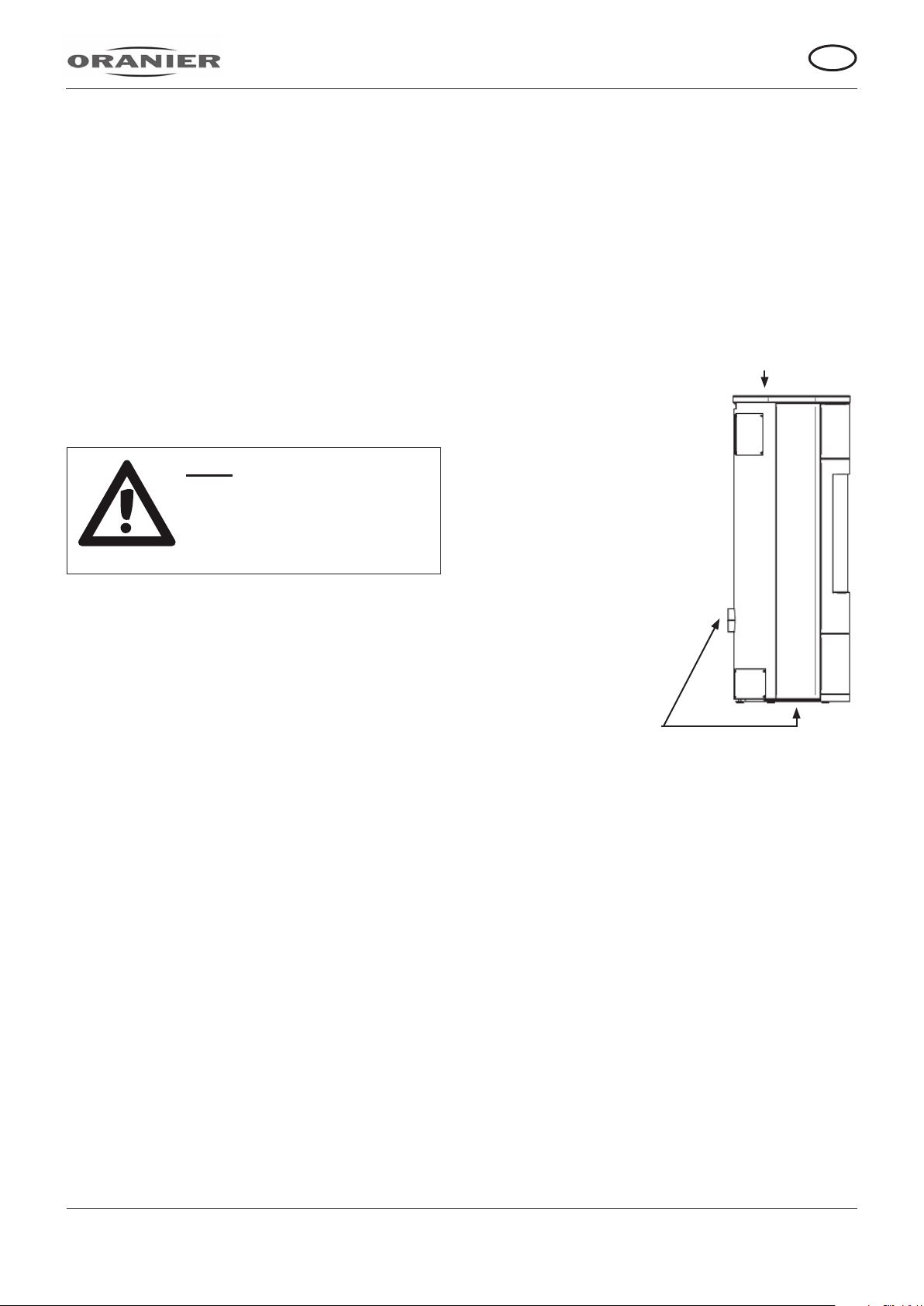
2.1 External combustion air supply
If necessary, the wood burning stove can
be equipped with a connection for an external combustion air supply (See Fig. 1):
For especially well-insulated rooms, an air supply from outside can be connected. The connection pipe requ ir ed f or th is is avail abl e as a n
accessory
Fig. 1
Flue tube opening
2. General
Your wood burning stove must be set up with
strict adherence to the relevant regional building regulations and following consultation with
the local profession al chimney s weep.
Once installed, he will also check that the replace is connected correctly.
During operation, a replace will draw oxygen
from the room in which it is set up. It is therefore absolutely essential to ensure an adequate supply of fresh ai r to this room.
If the stove is set up in rooms with particularly
tightly-closing windows and doors, malfunctions cannot be excluded.
If you are uncertain whether there is sufcient
air available for the stove in the room in which
you plan to set it up, ask your chimney sweep
for advice.
.
Wood burnin g stove
Connections for
external combustion
air supply
When attaching an external combustion
air supply, ensure that the pipes are tightly
sealed!
The combustion air is supplied exclusively via
a supply pipe with a ND of 100 mm, tted during installation. The air pipe should be made
from smooth ste e l or p lastic (drainag e p i p e).
The full length of the pipe should be no longer
than 6 m, have no reductions in the bore diameter and include no more than 3 90° elbow
pieces.
A safety grille attached in front of the external air supply opening must not be able to
accidentally restrict or occlude the supply air
cross-section.
It can be connected to a suitable air exhaust
chimney.
5
EN
In every case, care must be taken to ensure
that the combustion air requirement of around
30 m3/h is met at a feed pr e ssure of 4 Pa .
When not in use, all air slides should be kept
closed to ensure that no cold air is able to circulate via the chimney. The potential build-up
of condensation can be avoided
by insulating the air pipe.
The chimney draught must be able to overcome the additional resistances of a ring
system equipped with this setup.
2.2 Design
The wood burning stove series described in
these instructions a r e of “Design 1”.
The wood burning stove has a self-closing
rebox door and is approv ed onl y for use with
the rebox closed. Wood burning stoves of this
design may be connected to chimneys with
multiple ues, provided the dimensions of the
chimney permit this.
3. Flue tube connection and
setup of the wood burning sto ve
3.1 Connection of the ue tube
Your wood burning stove is connected up-
wards. To connect it to the chimney, a ue tube
made from 2 mm-thick sheet steel should be
used.
All of the connections between the stove and
the chimney must be stable, solid, tight and
free from tension. Use a temperature-resist-
ant sealing paste (e.g. boiler putty) to seal
off the stove outlets.
Ensure that the ue tube does not protrude into
the clear cross-section of the chimney.
We recommend using a liner.
The ue tube should run towards the chimney
in a slight up wa rds i ncline , b ut at th e v ery least
horizontally.
If the stove is connected to a chimney with
multiple ues, the hydraulic closure springs of
the rebox door must be removed under no cir-
cumstances.
The rebox door must be able to close inde-
pendently once fuel has been added so that
any inuence from the draught (feed pressure)
and associated risks and impairments of other
connected replaces can be avoided.
The design and condition of the chimney to
which the stove is to be connected plays a
key part in the fault-free operation of the wood
burning stove.
In all cases, have the suitability of the
chimney you intend to use checked by a
specialist.
This wood burning stove has been tested in
accordance with EN 13240.
Note:
The connection pieces required for a connection on the
ue gas side are not included
in the scope of delivery.
Caution!
If the feed pressure is too
low, or also too high
(draught), malfunctions can
occur.
If the value i s m ore than 25%
higher than the value listed
under Point 4 (Technical da ta:
"Feed pressur e at NHO"), corresponding measures must be
carried out on the chimne y.
6

EN
3.2 Setup of the wood burning stove
Fire safety regulations according to FeuVo
(mi nimum distances; see Fig . 2) must be complied with when setting up the applian ce.
FeuVo ("O rdinance on Firing Installations an d
Fuel Storage", or: Firing Ordinance for short)
is the legal basis for setting up and operating
ring installations.
Fig. 2
Caution!
For your own safety, you
must comply with the minimum distances specied to
installation walls, ammable
furnishings and objects and
for protection of the ooring!
Note:
Before heating the system for
the rst time, please remove
all documents a n d accessory
parts from the rebox and ash
box.
Remove all stick ers so there
is no residue from the v i ewing
pane.
Minimum distances that must be maintained:
A: 80 cm in the radia nt range of the pa n e
B1: 20 cm distance from th e wall at the rea r
B2: 30 cm distance from the wall at th e s i d e
C: 30 cm oor protection on the side of the
ller opening
D: 50 cm oor protection in front of the
ller opening
The rear (B1) and side (B2) minimum distances are also lis ted on your stove's type plate .
Caution!
Ensure before setup that the
oor (setup surface)
is able to support the weight
of the stove.
If necessary, use a suitable
supporting plate to distribute
the weight.
7

EN
4. Technical data
Wood burning stove type: POLAR NEO AQU A I
Design: 1
Nominal heat output: 10,0 kW
Water heat output: 6,0 kW
Energieefzienzklasse: A+
Energy efciency index
EEI: 111
Room heating capacity
DIN 18893 max.: 200 m
Height
incl. cover plate: 1320 mm
Width: 595 mm
Depth: 505 mm
Max. supply temp.: 95°C
Max. boiler pressure : 3,0 bar
Firebox H / W / D: 380 / 430 / 350 mm
Filler opening H / W: 530 / 480 mm
Max. rewood length: 35 cm
Weight steel / stone: 210 / 250 kg
Suitable for constant
operation and constant
ring: yes
Tested and approv ed
according to standard: EN 13240
1. BlmSchV-Stage 2: yes
Regensburger Standard: yes
Münchner Standard: yes
§15a B-VG Austria: yes
VKF Switzerland: yes
Ext. combustion
air supply: yes
Emissions and efciency values
(13% 0
; wood / BB7):
2
Efciency
(wood / BB7):: 83,6 / 84,1 %
CO: 1022 / 808 mg/m
NOx: 129 / 142 mg/m
CnHm: 70 / 73 mg/m
Particulate matter: 35 / 32 mg/m
3
3
3
3
3
Exhaust mass ow: 8,1 g/s
Feed pressure for NHO: 12,0 Pa
Exhaust temperature
at outlet: 227 °C
Approved fuels: - Firewood < 25% moisture
content (preferred fuel)
- Wood briquettes < 12%
moisture content,
- Lignite briquettes
Diameter of pipe outlet: 150 mm
Diameter of ue: 150 mm
Top outlet
(Base - LB outlet): 1305 mm
Top outlet
(FB - central outlet): 178 mm
Rear outlet
(Floor - LB outlet): -
Safety distance
At rear: 200 mm
At the side:: 200 mm
In the radiant range
of the viewing pane: 800 mm
Firebox lining:
Flat trivet: yes
Locking of the
Firebox door: hydraulic
Primary air control: yes
Secondary air control
Slider ventilation
Tertiary air control: yes
Water connections: 3/4“
Recommended content
buffer store: 300-500 l
Diameter of outlet of
external combustion air
supply (2x): 100 mm
Floor to centre
outlet: 351 mm
Front edge t o centra l
outlet: 283 mm
Vermiculite
: yes
8
 Loading...