

Page 1

TREMLORD 30
OWNER’S MANUAL
DESIGNED AN D ENGINEERED BY OR ANGE M USIC ELECTRON IC COMPAN Y LTD.
108 RI PON WAY, BOR EHAMWOOD, WD6 2JA, UK. ORANGEAMPS.COM
Page 2
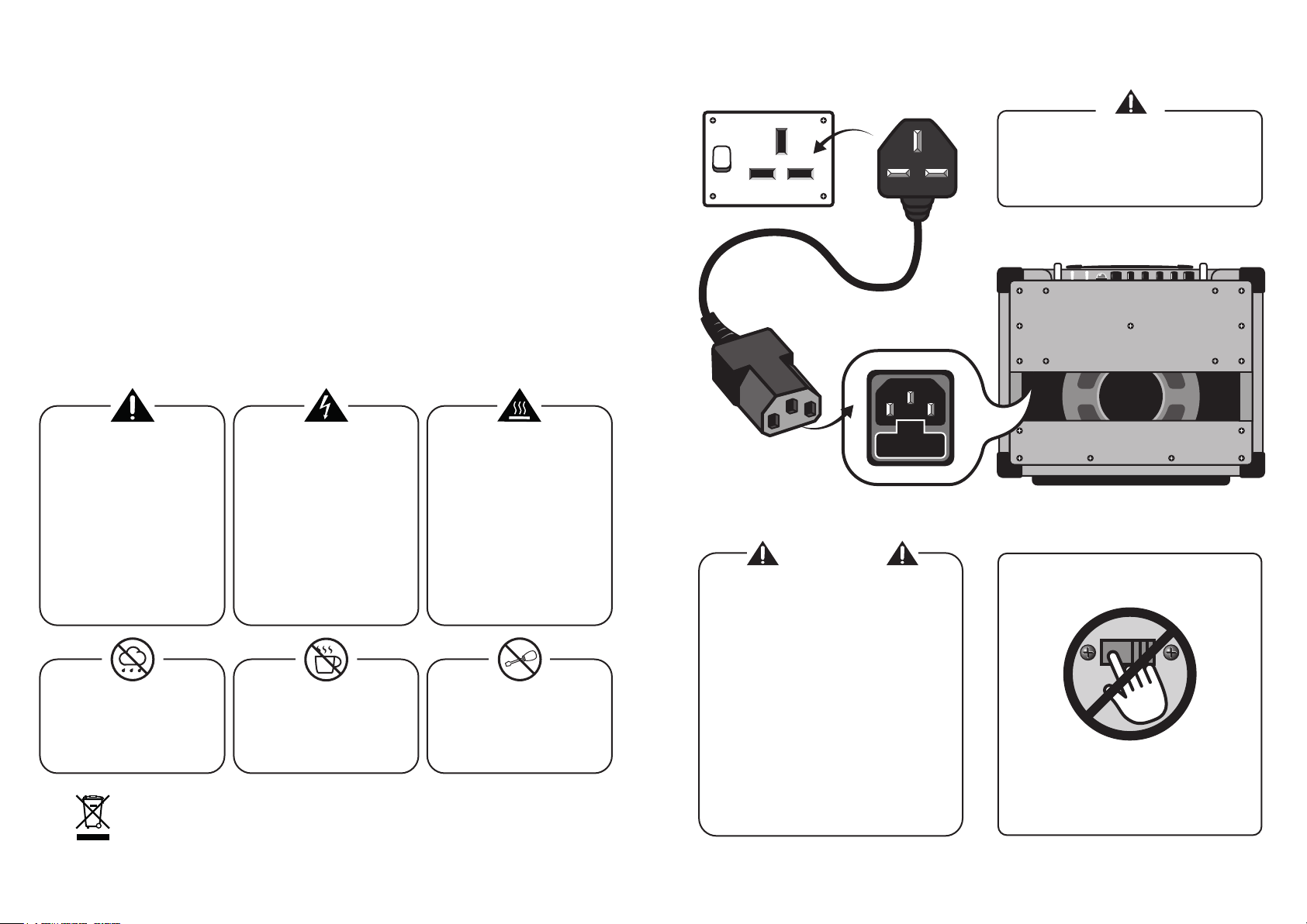
IMPORTANT SAFETY INSTRUCTIONS POWERING YOUR UNIT
1. Read these instructions.
2. Keep these instructions.
3. Heed all warnings.
4. Follow all instructions.
5. Do not use this apparatus near water.
6. Clean only with a dry cloth.
7. Do not block any ventilation openings. Install in accordance with the manufacturer’s instructions.
8.
Do not install near any heat sources such as radiators, heat registers, stoves, or other apparatus
(including amplifiers) that produce heat.
9. Do not defeat the safety purpose of the polarised or grounding-type plug. A polarised plug has two blades with
one wider than the other. A grounding type plug has two blades and a third grounding prong. The wide blade or
the third prong are provided for your safety. If the provided plug does not fit into your outlet, consult an electrician
for replacement of the obsolete outlet.
10. Protect the power cord from being walked on or pinched particularly at plugs, convenience receptacles, and the
point where they exit from the apparatus.
11. Only use attachments/accessories specified by the manufacturer.
12.
Use only with the cart, stand, tripod, bracket, or table specified by the manufacturer, or sold with the apparatus.
When a cart is used, use caution when moving the cart/apparatus combination to avoid injury from tip-over.
13. Unplug this apparatus during lightning storms or when unused for long periods of time.
14. Refer all servicing to qualified service personnel. Servicing is required when the apparatus has been damaged in
any way, such as power-supply cord or plug is damaged, liquid has been spilled or objects have fallen into the
apparatus, the apparatus has been exposed to rain or moisture, does not operate normally, or has been dropped.
WARNING
Connect the included power cord/plug to an
AC mains socket outlet with a protective
earthing connection.
The exclamation point within an
equilateral triangle and "WARNING"
are intended to alert the user to the
presence of important operating or
servicing instructions. Failure to
heed the instructions will result in
severe injury or death.
This equipment should be used
under the supervision of an adult
at all times.
To reduce the risk of fire and electric
shock do not expose this apparatus
to rain or moisture. For indoor use
only. Do not use in damp environ-
ments, e.g. bathrooms etc.
This symbol indicates this product is classified as Waste Electrical and Electronic Equipment
(WEEE) in the European Union and should not be discarded with household waste. Contact
your local authority for more information and details of your nearest approved disposal facility.
2 3
The lightning flash with arrowhead
symbol, within an equilateral
triangle, is intended to alert the user
to the presence of un-insulated
‘dangerous voltage’ within the
product’s enclosure that may be of
sufficient magnitude to constitute a
risk of electric shock to persons.
Terminals labelled as “SPEAKER
OUTPUTS” must be connected to a
speaker cabinet of the designated
load (Ω) rating using an un-shielded
two conductor cable for speaker use
at all times during operation.
Do not place objects containing
liquids on, or near the product.
Do not operate this apparatus or
connect/disconnect a power plug
whilst hands are wet.
The “Caution, hot surface” symbol
indicates that the marked item may
be hot.
Do not cover or block ventilation
openings. Ensure the apparatus is
installed with plenty of space around
the unit (> 6”/12.5cm) as this
apparatus may generate heat under
normal use. This equipment is not
intended to be used on soft support
(like beddings, blankets etc.). This
equipment should always be placed
on a flat, stable surface.
Do not attempt to gain access to
the interior of the product. No user
serviceable parts inside. Refer all
servicing to qualified servicing
personnel.
FUSE
WARNING
FUSE INFORMATION
The mains fuse is provided for your safety. The
fuse rating for your model and region is indicated
near the unit’s AC mains inlet
Do not replace with a fuse of a different type
T = Time Delay (“Slow Blow”)
mA or A = Rated current, expressed in mA or A
L = Low breaking capacity or;
H = High breaking capacity
If the mains fuse repeatedly blows,
contact your Orange dealer.
DO NOT TAMPER WITH VOLTAGE
SELECTOR SWITCH
The voltage selector switch is located on the rear
or side of the product. It is set at the factory for the
country or region in which the unit is intended to be
sold. If the unit is to be used oversees, contact
Orange Amplification.
Page 3

GENERAL USE FRONT PANEL
Before switching on the power, set the unit’s volume control(s) to minimum.
Ensure the correct speaker load is connected at all times during operation.
Refer to the section entitled “SPEAKER OUTPUTS”
Use good quality shielded instrument cable to connect your instrument to your unit’s input.
To prevent excessive hum and electrical noise, operate your amplifier and instruments as
far away as possible from other electronic devices. Examples include: refrigerators, motors,
air conditioners, television sets, radio receivers etc.
START UP PROCEDURE
FOR VALVE AMPLIFIERS
Before switching the POWER switch to the ON position,
ensure the HALF/STBY/FULL switch is set to the
STBY (Startup Tension Bypass) mode.
Leave the amp in STBY mode for at least 2 minutes
prior to performance. This will help prolong the life of
the valves [tubes]. After 2 minutes, switch to play mode
(FULL or HALF power). Select the STBY mode during
breaks in performance.
SELECTING STBY OR PLAY MODE:
OUTPUT (FULL / HALF)
This switch toggles between FULL and HALF
power modes. In HALF power mode, the volume
will be reduced and output valve overdrive can be
achieved at lower output levels. The centre
position selects STBY mode.
SERVICING INFORMATION FOR
VALVE AMPLIFIERS
Periodic valve renewal should be considered part of
owning a quality valve [tube] amplifier. The rate of valve
wear is dependent on many factors, but if you notice a
change in the performance of your amplifier, it is likely a
result of valve decline. Valves can fail at any time.
Output valves (EL84, EL34, 6550 etc.) are subject to
more stress than preamp valves (12AX7, 12AT7 etc.)
and may require more regular replacement. Consult
your service centre/dealer for more information.
Output valves should always be
replaced with matched sets, though
not all models require a bias
adjustment. Contact your
Orange dealer for more
information.
Bias adjustment should
only be performed by
authorised service
personnel.
The fuse labelled "HT
FUSE" will blow in the
event of output valve
failure. The output valve(s)
should be replaced, and
the HT fuse replaced with
the correct 250V type.
The rating is indicated on
the product near the HT
fuse holder.
Our Orange Valve Tester
can be used to help match
valves and check valve
health.
Visit orangeamps.com for
more information.
FRONT ICONS
INPUT
¼” instrument jack socket.
Increases the output VOLUME of the
Adjusts the lower frequency response.
Increasing the BASS produces deeper
Adjusts the high frequency response.
Increase the TREBLE for brighter tones
VOLUME
amplifier
BASS
sounds.
TREBLE
or reduce for a warmer sound.
REAR ICONS
Used to place external effects between the
amplifier’s preamplifier section and output
section. Connect the SEND jack to the input
of external effects. Connect the output of
external effects to the RETURN jack. The
FX LOOP becomes active after TREMOLO
FX LOOP
& before REVERB
TREMOLO SPEED
This controls the SPEED of the tremolo.
Only the left dial is active unless using a
foot switch. (see rear connections page 7)
TREMOLO DEPTH
Increases / decreases the amount of
Increases / decreases the amount of
The lamp will illuminate to indicate the
Refer to page 4 for the
HALF/STBY/FULL switch.
Connect a latching footswitch (e.g.
Orange FS-1) to remotely select between:
TREMOLO.
REVERB
REVERB.
POWER
power is switched to ON.
FOOTSWITCH
SPEED controls
TREMOLO on / off
REVERB on / off
4 5
Page 4

TREMLORD REAR CONNECTIONS
FRONT
SPEAKER OUTPUTS
The TREMLORD 30 must be connected to a speaker
load (Ω) at all times during operation.
The HEADROOM / BEDROOM
attenuator switch works with the
4 OUTPUT VALVES /
2 OUTPUT VALVES
switch to vary the output power:
HEADROOM
= 30 Watts
(4 OUTPUT VALVES)
HEADROOM
= 15 Watts
(2 OUTPUT VALVES)
BEDROOM
= 2 Watts
(4 OUTPUT VALVES)
BEDROOM
= 1 Watt
(2 OUTPUT VALVES)
2 x 16Ω CABINETS
2 x EXTERNAL
SPEAKERS
( 16 Ω ONLY )
1 x 8Ω CABINET
FOOTSWITCHES
TREMOLO FOOTSWITCH
Switch TREMOLO effect ON / OFF
SPEED FOOTSWITCH
Switch between the two SPEED dials
REVERB FOOTSWITCH
Switch REVERB effect ON / OFF
EXTENSION CABINET
DISCONNECT
INTERNAL
SPEAKER
EXTENSION SPEAKER
MONO
PEDAL
FX LOOP becomes active
after TREMOLO
& before REVERB
( 16 Ω ONLY )
1 x 16Ω CABINET
INOUT
RECONNECT
INTERNAL SPEAKER
AS SHOWN
NEVER PLUG ANYTHING OTHER THAN A SPEAKER
CABLE INTO THE SPEAKER OUTPUT. only connect
speaker cabinets as shown.
Never use AN instrument cable to
connect speakers. Only use unshielded
two conductor speaker cable.
Never connect x 2 cabinets of
different impedances (Ω).
Ensure the speaker cabinet’s power handling rating
(Watts RMS) is suitable for your amplifier. If you are
unsure, contact your Orange dealer.
VALVE LAYOUT
1 x EXTERNAL SPEAKER
( 8 Ω ONLY )
DISCONNECT
INTERNAL
SPEAKER
REPLACE INTERNAL SPEAKER
WITH 1 x EXTERNAL SPEAKER
( 16 Ω ONLY )
DISCONNECT
INTERNAL
SPEAKER
76
 Loading...